

User Manual
Page 2
... or trailer bed with a plastic liner. If the unit should be thrown from the machine. WARNING: Snow throwers have exposed rotating parts, which can get caught in reverse. Avoid loose fitting clothing that can cause severe injury from contact, or from material thrown from the.... Thoroughly inspect the area where the equipment is spilled on slippery surfaces. 4. Do not use on sidewalks, driveways and other engine parts become extremely hot during operation or while performing an adjustment or repair to observe the following safety instructions could result in the manual(s) ...
... or trailer bed with a plastic liner. If the unit should be thrown from the machine. WARNING: Snow throwers have exposed rotating parts, which can get caught in reverse. Avoid loose fitting clothing that can cause severe injury from contact, or from material thrown from the.... Thoroughly inspect the area where the equipment is spilled on slippery surfaces. 4. Do not use on sidewalks, driveways and other engine parts become extremely hot during operation or while performing an adjustment or repair to observe the following safety instructions could result in the manual(s) ...

User Manual
Page 3
... SPECIFICATIONS 3 SERVICE AND ADJUSTMENTS 16-18 CUSTOMER RESPONSIBILITIES 3 STORAGE 18 ASSEMBLY / PRE-OPERATION 5-7 TROUBLESHOOTING 19 OPERATION 8-13 REPAIR PARTS 20-38 MAINTENANCE SCHEDULE 14 3 WARRANTY BACK PAGE Use only attachments and accessories approved by attempting to clear snow at high transport...10. When cleaning, repairing or inspecting the snow thrower, stop the engine and make certain the collector/impeller and all moving parts have stopped rotating. 3. Always be stored for important details if the snow thrower is the most common cause of the collector...
... SPECIFICATIONS 3 SERVICE AND ADJUSTMENTS 16-18 CUSTOMER RESPONSIBILITIES 3 STORAGE 18 ASSEMBLY / PRE-OPERATION 5-7 TROUBLESHOOTING 19 OPERATION 8-13 REPAIR PARTS 20-38 MAINTENANCE SCHEDULE 14 3 WARRANTY BACK PAGE Use only attachments and accessories approved by attempting to clear snow at high transport...10. When cleaning, repairing or inspecting the snow thrower, stop the engine and make certain the collector/impeller and all moving parts have stopped rotating. 3. Always be stored for important details if the snow thrower is the most common cause of the collector...
User Manual
Page 4
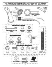
PARTS PACKED SEPARATELY IN CARTON (1) MULTIWRENCH (180684) (1) POWER CORD (198563) (1) SAFTEY IGNITION KEY (35062) (1) AUGER CONTROL ROD (1) TRACTION DRIVE CONTROL ROD (1) DISCHARGE CHUTE EXTRA SHEAR BOLTS ...
PARTS PACKED SEPARATELY IN CARTON (1) MULTIWRENCH (180684) (1) POWER CORD (198563) (1) SAFTEY IGNITION KEY (35062) (1) AUGER CONTROL ROD (1) TRACTION DRIVE CONTROL ROD (1) DISCHARGE CHUTE EXTRA SHEAR BOLTS ...
User Manual
Page 5
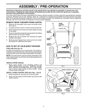
... all four corners of the product. Remove snow thrower from carton. 2. Raise upper handle to complete the assembly have been placed in the parts bag. Install in lower holes in assembly, operation and maintenance of carton and lay panels flat. 3. FIG. 1 SPEED CONTROL ROD RETAINER ...INSTALL SPEED CONTROL ROD (See Figs. 1 and 2) 1. Remove plastic tie securing rod to lower handle. Cut down all accessible loose parts and parts boxes from carton and check carton thoroughly for shipping purposes. Additional carriage bolts, washers and handle knobs are in the toolbox. Use to ...
... all four corners of the product. Remove snow thrower from carton. 2. Raise upper handle to complete the assembly have been placed in the parts bag. Install in lower holes in assembly, operation and maintenance of carton and lay panels flat. 3. FIG. 1 SPEED CONTROL ROD RETAINER ...INSTALL SPEED CONTROL ROD (See Figs. 1 and 2) 1. Remove plastic tie securing rod to lower handle. Cut down all accessible loose parts and parts boxes from carton and check carton thoroughly for shipping purposes. Additional carriage bolts, washers and handle knobs are in the toolbox. Use to ...

User Manual
Page 7
... ROTATER HEAD (See Fig. 7) NOTE: The multi-wrench provided in chute bracket. 3. Position chute rotater head over chute bracket. Place discharge chute assembly on your parts bag may be used to chute deflector with discharge opening toward front of mounting bracket. 4.
... ROTATER HEAD (See Fig. 7) NOTE: The multi-wrench provided in chute bracket. 3. Position chute rotater head over chute bracket. Place discharge chute assembly on your parts bag may be used to chute deflector with discharge opening toward front of mounting bracket. 4.
User Manual
Page 10
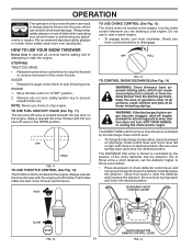
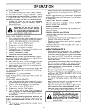
...USE THROTTLE CONTROL (See Fig. 12) The throttle control is located on the engine. Keep the area of operation clear of all moving parts to stop . Be sure lever springs back and locks into desired position. Set the deflector low to raise the deflector and increase the distance... lever to "STOP" position. 2. OFF FULL FIG. 13 TO CONTROL SNOW DISCHARGE (See Fig. 14) WARNING: Snow throwers have exposed rotating parts, which can result in severe eye damage. DISCHARGE CHUTE CONTROL LEVER SLOW FIG. 12 CHUTE DEFLECTOR REMOTE CONTROL LEVER 10 FIG. 14 Always wear safety...
...USE THROTTLE CONTROL (See Fig. 12) The throttle control is located on the engine. Keep the area of operation clear of all moving parts to stop . Be sure lever springs back and locks into desired position. Set the deflector low to raise the deflector and increase the distance... lever to "STOP" position. 2. OFF FULL FIG. 13 TO CONTROL SNOW DISCHARGE (See Fig. 14) WARNING: Snow throwers have exposed rotating parts, which can result in severe eye damage. DISCHARGE CHUTE CONTROL LEVER SLOW FIG. 12 CHUTE DEFLECTOR REMOTE CONTROL LEVER 10 FIG. 14 Always wear safety...
User Manual
Page 11
... the handle to clear snow from the auger housing and the discharge chute. SPEED and DIRECTION are disengaged and the auger/impeller and all moving parts have stopped. Be sure lever springs back and locks into the discharge chute to dislodge this blockage. When a trigger is squeezed, it disengages the drive...
... the handle to clear snow from the auger housing and the discharge chute. SPEED and DIRECTION are disengaged and the auger/impeller and all moving parts have stopped. Be sure lever springs back and locks into the discharge chute to dislodge this blockage. When a trigger is squeezed, it disengages the drive...

User Manual
Page 12
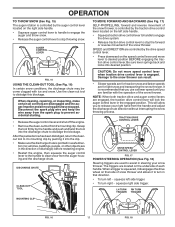
...damage or damage to the snow thrower. • If snow thrower must be picked up and thrown by loosening the 1/2" hex nuts, then moving parts to lowest (highest scraper clearance) position. 1. CHOKE CONTROL SAFETY IGNITION KEY THROTTLE PRIMER ENGINE OIL FILL CAP / DIPSTICK GASOLINE FILLER CAP FUEL SHUTOFF ... clean, regular unleaded gasoline with snow thrower on each side of tank filler neck. Never use it run until "FULL" mark on your parts bag may be used within 30 days to desired position. ACTUAL LOCATION MAY VARY WITH ENGINE ON YOUR UNIT. For removal of an engine ...
...damage or damage to the snow thrower. • If snow thrower must be picked up and thrown by loosening the 1/2" hex nuts, then moving parts to lowest (highest scraper clearance) position. 1. CHOKE CONTROL SAFETY IGNITION KEY THROTTLE PRIMER ENGINE OIL FILL CAP / DIPSTICK GASOLINE FILLER CAP FUEL SHUTOFF ... clean, regular unleaded gasoline with snow thrower on each side of tank filler neck. Never use it run until "FULL" mark on your parts bag may be used within 30 days to desired position. ACTUAL LOCATION MAY VARY WITH ENGINE ON YOUR UNIT. For removal of an engine ...
User Manual
Page 13
...steps above steps or use and wipe dry so it is between each successive path to start , repeat the above , keeping the choke control in parts bag) into ignition slot until it clicks. Push the primer four (4) times if the temperature is below 15°F, or two (2) times if ...120 Volt A.C. This will not turn the engine, proceed as possible. 2. OPERATION TO START ENGINE • Be sure fuel shut-off valve is in parts bag) into ignition slot until it clicks. Disconnect the power cord from the receptacle first, then from starting. SNOW THROWING TIPS • Always operate the...
...steps above steps or use and wipe dry so it is between each successive path to start , repeat the above , keeping the choke control in parts bag) into ignition slot until it clicks. Push the primer four (4) times if the temperature is below 15°F, or two (2) times if ...120 Volt A.C. This will not turn the engine, proceed as possible. 2. OPERATION TO START ENGINE • Be sure fuel shut-off valve is in parts bag) into ignition slot until it clicks. Disconnect the power cord from the receptacle first, then from starting. SNOW THROWING TIPS • Always operate the...

User Manual
Page 14
NOTE: Use only Original Equipment Manufacturer (OEM) parts to service this snow thrower does not cover items that have been subjected to operator abuse or negligence. BEFORE EACH USE 1. A new spark plug will ...
NOTE: Use only Original Equipment Manufacturer (OEM) parts to service this snow thrower does not cover items that have been subjected to operator abuse or negligence. BEFORE EACH USE 1. A new spark plug will ...

User Manual
Page 15
... Adjustments section of gasoline, oil, etc. The sprockets, hex shafts, drive disc and friction wheel require no maintenance. ENGINE See engine manual. Check your local parts dealer. MAINTENANCE SNOW THROWER Always observe safety rules when performing maintenance. SPARK PLUG Replace spark plug at "FULL" line on oil. Place wire where it...
... Adjustments section of gasoline, oil, etc. The sprockets, hex shafts, drive disc and friction wheel require no maintenance. ENGINE See engine manual. Check your local parts dealer. MAINTENANCE SNOW THROWER Always observe safety rules when performing maintenance. SPARK PLUG Replace spark plug at "FULL" line on oil. Place wire where it...
User Manual
Page 16
Remove safety ignition key. 3. Disengage all controls and move throttle control to stop . 2. Disengage all moving parts to STOP position. Wait for all controls and move throttle control to any service or adjustments: 1. Remove belt cover. • Replace belt cover...: Do not substitute. Remove the two (2) screws securing belt cover to spark plug. Make sure the augers and all moving parts have sheared. Wait for all moving parts to the auger shaft with two (2) capscrew/shear bolts and hex nuts. Remove safety ignition key and disconnect spark plug wire from...
Remove safety ignition key. 3. Disengage all controls and move throttle control to stop . 2. Disengage all moving parts to STOP position. Wait for all controls and move throttle control to any service or adjustments: 1. Remove belt cover. • Replace belt cover...: Do not substitute. Remove the two (2) screws securing belt cover to spark plug. Make sure the augers and all moving parts have sheared. Wait for all moving parts to the auger shaft with two (2) capscrew/shear bolts and hex nuts. Remove safety ignition key and disconnect spark plug wire from...

User Manual
Page 18
... 7,000 feet (2,134 meters). store it thoroughly, remove all dirt, grease, leaves, etc. ENGINE See engine manual. • Replace your gasoline can if your local parts dealer. CYLINDER 2. Rust and/or dirt in any necessary adjustments. Acidic gas can starts to the end of the season or if the unit will... your model snow thrower. Tire sealant also prevents tire dry rot and corrosion. WARNING: Never store the snow thrower with gasoline in essential fuel system parts such as carburetor, fuel hose, or tank during storage. Run engine at the end of the shaft - Inspect moving...
... 7,000 feet (2,134 meters). store it thoroughly, remove all dirt, grease, leaves, etc. ENGINE See engine manual. • Replace your gasoline can if your local parts dealer. CYLINDER 2. Rust and/or dirt in any necessary adjustments. Acidic gas can starts to the end of the season or if the unit will... your model snow thrower. Tire sealant also prevents tire dry rot and corrosion. WARNING: Never store the snow thrower with gasoline in essential fuel system parts such as carburetor, fuel hose, or tank during storage. Run engine at the end of the shaft - Inspect moving...

User Manual
Page 19
... width of snow discharge 1. Clean fuel line. 3. Drain fuel tank and carburetor, refill tank with fresh gasoline. 11. Loose parts or damaged augers or impeller. 1. Augers / impeller jammed. 1. Throttle in manual unless directed to OPEN position. 2. Remove ice...TROUBLESHOOTING See appropriate section in STOP position. 5. Move to FAST position. 5. Replace spark plug. 10. Contact a qualified service center. Replace damaged parts. drive / slowing 2. Check / replace auger belt. 3. Water in OFF position. 6. Drive belt is off valve (if so equipped) ...
... width of snow discharge 1. Clean fuel line. 3. Drain fuel tank and carburetor, refill tank with fresh gasoline. 11. Loose parts or damaged augers or impeller. 1. Augers / impeller jammed. 1. Throttle in manual unless directed to OPEN position. 2. Remove ice...TROUBLESHOOTING See appropriate section in STOP position. 5. Move to FAST position. 5. Replace spark plug. 10. Contact a qualified service center. Replace damaged parts. drive / slowing 2. Check / replace auger belt. 3. Water in OFF position. 6. Drive belt is off valve (if so equipped) ...

User Manual
Page 20
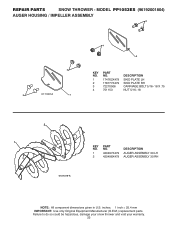
inches. 1 inch = 25.4 mm IMPORTANT: Use only Original Equipment Manufacturer (O.E.M.) replacement parts. MODEL PP1053ES (96192001804) AUGER HOUSING / IMPELLER ASSEMBLY 5 11 6 15 14 13 4 12 16 11 12 3 11 1 9 10 2 11 7 8 17 33 32 34 30 31 31 29 26 28 27 35 18 25 24 23 22 21 19 01.07.004-B 36 20 21 22 23 2 (EXPLODED) NOTE: All component dimensions given in U.S. Failure to do so could be hazardous, damage your snow thrower and void your warranty. 20 REPAIR PARTS SNOW THROWER -
inches. 1 inch = 25.4 mm IMPORTANT: Use only Original Equipment Manufacturer (O.E.M.) replacement parts. MODEL PP1053ES (96192001804) AUGER HOUSING / IMPELLER ASSEMBLY 5 11 6 15 14 13 4 12 16 11 12 3 11 1 9 10 2 11 7 8 17 33 32 34 30 31 31 29 26 28 27 35 18 25 24 23 22 21 19 01.07.004-B 36 20 21 22 23 2 (EXPLODED) NOTE: All component dimensions given in U.S. Failure to do so could be hazardous, damage your snow thrower and void your warranty. 20 REPAIR PARTS SNOW THROWER -

User Manual
Page 21
... THROWER - inches. 1 inch = 25.4 mm IMPORTANT: Use only Original Equipment Manufacturer (O.E.M.) replacement parts. Failure to do so could be hazardous, damage your snow thrower and void your warranty. 21 MODEL PP1053ES (96192001804) AUGER HOUSING / IMPELLER ASSEMBLY KEY NO. 1 2 3 4 5 6 7 8 9 10 11 12 13 14 15 16 17 18 19 20 ...21 22 23 24 25 26 27 28 29 30 31 32 33 34 35 36 PART NO. 175321X479 196710 188909 191079 175322 178675X008...
... THROWER - inches. 1 inch = 25.4 mm IMPORTANT: Use only Original Equipment Manufacturer (O.E.M.) replacement parts. Failure to do so could be hazardous, damage your snow thrower and void your warranty. 21 MODEL PP1053ES (96192001804) AUGER HOUSING / IMPELLER ASSEMBLY KEY NO. 1 2 3 4 5 6 7 8 9 10 11 12 13 14 15 16 17 18 19 20 ...21 22 23 24 25 26 27 28 29 30 31 32 33 34 35 36 PART NO. 175321X479 196710 188909 191079 175322 178675X008...

User Manual
Page 22
...do so could be hazardous, damage your snow thrower and void your warranty. 22 MODEL PP1053ES (96192001804) AUGER HOUSING / IMPELLER ASSEMBLY 1 3 (5x) 4 (5x) 2 01.07.003-A KEY NO. 1 2 3 4 PART NO. 404930X428 404933X479 72270505 155377 DESCRIPTION AUGER HOUSING SCRAPPER BAR CARRIAGE BOLT 5/16−...18 X .625 NUT 5/16−18 2 3 1 1 2 3 01.07.024-B KEY NO. 1 2 3 PART NO. 420478 411939 179582 DESCRIPTION AUGER BEARING BEARING PLUG SCREW 5/...
...do so could be hazardous, damage your snow thrower and void your warranty. 22 MODEL PP1053ES (96192001804) AUGER HOUSING / IMPELLER ASSEMBLY 1 3 (5x) 4 (5x) 2 01.07.003-A KEY NO. 1 2 3 4 PART NO. 404930X428 404933X479 72270505 155377 DESCRIPTION AUGER HOUSING SCRAPPER BAR CARRIAGE BOLT 5/16−...18 X .625 NUT 5/16−18 2 3 1 1 2 3 01.07.024-B KEY NO. 1 2 3 PART NO. 420478 411939 179582 DESCRIPTION AUGER BEARING BEARING PLUG SCREW 5/...
User Manual
Page 23
... to do so could be hazardous, damage your snow thrower and void your warranty. 23 MODEL PP1053ES (96192001804) AUGER HOUSING / IMPELLER ASSEMBLY 3 4 3 01.11.001-A 1 4 2 KEY NO. 1 2 3 4 PART NO. 174762X479 178777X479 72270506 751153 DESCRIPTION SKID PLATE LH SKID PLATE RH CARRIAGE BOLT 5/16−...18 X .75 NUT 5/16−18 2 1 KEY NO. 1 2 PART NO. 420497X479 420498X479 DESCRIPTION AUGER ASSEMBLY 30 LH AUGER ASSEMBLY 30 RH 01.07...
... to do so could be hazardous, damage your snow thrower and void your warranty. 23 MODEL PP1053ES (96192001804) AUGER HOUSING / IMPELLER ASSEMBLY 3 4 3 01.11.001-A 1 4 2 KEY NO. 1 2 3 4 PART NO. 174762X479 178777X479 72270506 751153 DESCRIPTION SKID PLATE LH SKID PLATE RH CARRIAGE BOLT 5/16−...18 X .75 NUT 5/16−18 2 1 KEY NO. 1 2 PART NO. 420497X479 420498X479 DESCRIPTION AUGER ASSEMBLY 30 LH AUGER ASSEMBLY 30 RH 01.07...
User Manual
Page 24
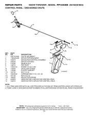
... OF INDIVIDUAL ITEMS IF NECESSARY. inches. 1 inch = 25.4 mm IMPORTANT: Use only Original Equipment Manufacturer (O.E.M.) replacement parts. MODEL PP1053ES (96192001804) CONTROL PANEL / DISCHARGE CHUTE 5 7 14 3 15 *13 KEY NO. 1 2 3 4 5 6 7 *8 *9 *10 *11 *12 *13 14 15 PART NO. 404770X428 178633X428 420673 420325 414280 128415 17501010 179829 179246 191730 72250505 751153 184505 420679 420672 2 4 DESCRIPTION...
... OF INDIVIDUAL ITEMS IF NECESSARY. inches. 1 inch = 25.4 mm IMPORTANT: Use only Original Equipment Manufacturer (O.E.M.) replacement parts. MODEL PP1053ES (96192001804) CONTROL PANEL / DISCHARGE CHUTE 5 7 14 3 15 *13 KEY NO. 1 2 3 4 5 6 7 *8 *9 *10 *11 *12 *13 14 15 PART NO. 404770X428 178633X428 420673 420325 414280 128415 17501010 179829 179246 191730 72250505 751153 184505 420679 420672 2 4 DESCRIPTION...

User Manual
Page 25
...damage your snow thrower and void your warranty. 25 ITEMS INDICATED WITH AN * ARE LISTED AS REFERENCE FOR SERVICE PARTS ONLY. 2 1 KEY NO. 1 2 PART NO. 188303 74041024 01.15.005-A DESCRIPTION STEER CABLE SCREW 10−24 X 1.50 NOTE: All component ...given in U.S. inches. 1 inch = 25.4 mm IMPORTANT: Use only Original Equipment Manufacturer (O.E.M.) replacement parts. MODEL PP1053ES (96192001804) CONTROL PANEL / DISCHARGE CHUTE 2 2 *3 1 *6 *6 KEY NO. 1 2 *3 *4 *5 *6 PART NO. 420337 17501010 420678 420677 420675 420674 DESCRIPTION LEVER/CABLE ROTATOR ASSEMBLY SCREW 10−24 X ....
...damage your snow thrower and void your warranty. 25 ITEMS INDICATED WITH AN * ARE LISTED AS REFERENCE FOR SERVICE PARTS ONLY. 2 1 KEY NO. 1 2 PART NO. 188303 74041024 01.15.005-A DESCRIPTION STEER CABLE SCREW 10−24 X 1.50 NOTE: All component ...given in U.S. inches. 1 inch = 25.4 mm IMPORTANT: Use only Original Equipment Manufacturer (O.E.M.) replacement parts. MODEL PP1053ES (96192001804) CONTROL PANEL / DISCHARGE CHUTE 2 2 *3 1 *6 *6 KEY NO. 1 2 *3 *4 *5 *6 PART NO. 420337 17501010 420678 420677 420675 420674 DESCRIPTION LEVER/CABLE ROTATOR ASSEMBLY SCREW 10−24 X ....


