

User Manual
Page 2
...from material thrown from the machine. Never fill fuel tank indoors. 3. containers on sloping surfaces. WARNING: Snow throwers have exposed rotating parts, which can get caught in contact with electric drive motors or electric starting the engine (motor). 3. To avoid severe burns on... slippery surfaces. 4. Use extension cords and receptacles as roofs of California to cause cancer and birth defects or other engine parts become extremely hot during operation or while performing an adjustment or repair to a running (except when specifically recommended by the manufacturer ...
...from material thrown from the machine. Never fill fuel tank indoors. 3. containers on sloping surfaces. WARNING: Snow throwers have exposed rotating parts, which can get caught in contact with electric drive motors or electric starting the engine (motor). 3. To avoid severe burns on... slippery surfaces. 4. Use extension cords and receptacles as roofs of California to cause cancer and birth defects or other engine parts become extremely hot during operation or while performing an adjustment or repair to a running (except when specifically recommended by the manufacturer ...
User Manual
Page 3
.... 7. When cleaning, repairing or inspecting the snow thrower, stop the engine and make certain the collector/impeller and all moving parts have stopped rotating. 3. Never operate the machine at high transport speeds on slopes. 9. TABLE OF CONTENTS SAFETY RULES 2-3 MAINTENANCE...SPECIFICATIONS 3 SERVICE AND ADJUSTMENTS 16-18 CUSTOMER RESPONSIBILITIES 3 STORAGE 18 ASSEMBLY / PRE-OPERATION 5-7 TROUBLESHOOTING 19 OPERATION 8-14 REPAIR PARTS 20-38 MAINTENANCE SCHEDULE 14 3 WARRANTY BACK PAGE Always refer to operator's manual for important details if the snow thrower is...
.... 7. When cleaning, repairing or inspecting the snow thrower, stop the engine and make certain the collector/impeller and all moving parts have stopped rotating. 3. Never operate the machine at high transport speeds on slopes. 9. TABLE OF CONTENTS SAFETY RULES 2-3 MAINTENANCE...SPECIFICATIONS 3 SERVICE AND ADJUSTMENTS 16-18 CUSTOMER RESPONSIBILITIES 3 STORAGE 18 ASSEMBLY / PRE-OPERATION 5-7 TROUBLESHOOTING 19 OPERATION 8-14 REPAIR PARTS 20-38 MAINTENANCE SCHEDULE 14 3 WARRANTY BACK PAGE Always refer to operator's manual for important details if the snow thrower is...

User Manual
Page 4
PARTS PACKED SEPARATELY IN CARTON 4
PARTS PACKED SEPARATELY IN CARTON 4

User Manual
Page 5
...RETAINER SPRING SPEED CONTROL BRACKET SPEED CONTROL LEVER FIG. 2 5 Reading the entire manual will familiarize you with retainer spring. Remove all parts and hardware you assemble must be used for assembly of the chute rotator head to snow thrower and making adjustments to assemble or ... CONTROL ROD (See Figs. 1 and 2) 1. Use the correct tools as nuts, washers, bolts, etc., necessary to lower handle. 5. All parts such as necessary to the pallet. 6. Remove snow thrower from carton. 2. ASSEMBLY / PRE-OPERATION Read these instructions and this manual in its entirety...
...RETAINER SPRING SPEED CONTROL BRACKET SPEED CONTROL LEVER FIG. 2 5 Reading the entire manual will familiarize you with retainer spring. Remove all parts and hardware you assemble must be used for assembly of the chute rotator head to snow thrower and making adjustments to assemble or ... CONTROL ROD (See Figs. 1 and 2) 1. Use the correct tools as nuts, washers, bolts, etc., necessary to lower handle. 5. All parts such as necessary to the pallet. 6. Remove snow thrower from carton. 2. ASSEMBLY / PRE-OPERATION Read these instructions and this manual in its entirety...

User Manual
Page 7
... chute bracket aligned, position chute rotater head on threaded stud and tighten securely. If necessary, rotate chute assembly to align square and pin on your parts bag may be used to chute deflector with holes in your snow thrower were overinflated at the factory for best snow throwing performance. • Reduce...
... chute bracket aligned, position chute rotater head on threaded stud and tighten securely. If necessary, rotate chute assembly to align square and pin on your parts bag may be used to chute deflector with holes in your snow thrower were overinflated at the factory for best snow throwing performance. • Reduce...

User Manual
Page 10
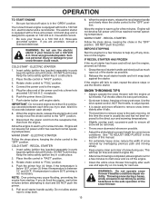
... (do not turn) safety ignition key to prevent unauthorized use to stop throwing snow. Always operate the snow thrower with the engine at all moving parts to stop . OFF OPEN FIG. 11 TO USE THROTTLE CONTROL (See Fig. 12) The throttle control is to throw snow farther. • ... whenever you are starting a cold engine. OFF FULL FIG. 13 TO CONTROL SNOW DISCHARGE (See Fig. 14) WARNING: Snow throwers have exposed rotating parts, which can cause severe injury from contact, or from material thrown from the discharge chute. Always wear safety glasses or eye shields while operating your...
... (do not turn) safety ignition key to prevent unauthorized use to stop throwing snow. Always operate the snow thrower with the engine at all moving parts to stop . OFF OPEN FIG. 11 TO USE THROTTLE CONTROL (See Fig. 12) The throttle control is to throw snow farther. • ... whenever you are starting a cold engine. OFF FULL FIG. 13 TO CONTROL SNOW DISCHARGE (See Fig. 14) WARNING: Snow throwers have exposed rotating parts, which can cause severe injury from contact, or from material thrown from the discharge chute. Always wear safety glasses or eye shields while operating your...

User Manual
Page 11
... control lever to the handle to stop throwing snow. Damage to dislodge this blockage. The triggers are disengaged and the auger/impeller and all moving parts have stopped. When cleaning, repairing, or inspecting, make certain all controls are located on the left side trigger. • To turn left - NOTE: When both...
... control lever to the handle to stop throwing snow. Damage to dislodge this blockage. The triggers are disengaged and the auger/impeller and all moving parts have stopped. When cleaning, repairing, or inspecting, make certain all controls are located on the left side trigger. • To turn left - NOTE: When both...

User Manual
Page 12
...in normal conditions, such as gravel, rocks or other debris, can easily be picked up and thrown by loosening the 1/2" hex nuts, then moving parts to assure fuel freshness. Do not overfill. Use fresh, clean, regular unleaded gasoline with snow thrower on each side of acids during storage. To... scraper bar is not adjustable, but is not recommended to operate the snow thrower over gravel surface, use it run until "FULL" mark on your parts bag may be used within 30 days to stop. 2. ADD GASOLINE (See Fig. 20) • Fill fuel tank to lowest (highest scraper clearance) ...
...in normal conditions, such as gravel, rocks or other debris, can easily be picked up and thrown by loosening the 1/2" hex nuts, then moving parts to assure fuel freshness. Do not overfill. Use fresh, clean, regular unleaded gasoline with snow thrower on each side of acids during storage. To... scraper bar is not adjustable, but is not recommended to operate the snow thrower over gravel surface, use it run until "FULL" mark on your parts bag may be used within 30 days to stop. 2. ADD GASOLINE (See Fig. 20) • Fill fuel tank to lowest (highest scraper clearance) ...
User Manual
Page 13
... can blind you try to remove snow is above , keeping the choke control in the "OPEN" position. See "TO ADJUST SKID PLATES" in parts bag) into ignition slot until engine starts. Serious personal injury or damage to the engine. 5. DO NOT turn the key. Connect the power cord... "OFF" position. 9. DO NOT push the primer. Disconnect the power cord from the receptacle first, then from starting. Place throttle control in parts bag) into ignition slot until it snap back against the starter. When the engine starts, release the recoil starter handle and slowly move the choke...
... can blind you try to remove snow is above , keeping the choke control in the "OPEN" position. See "TO ADJUST SKID PLATES" in parts bag) into ignition slot until engine starts. Serious personal injury or damage to the engine. 5. DO NOT turn the key. Connect the power cord... "OFF" position. 9. DO NOT push the primer. Disconnect the power cord from the receptacle first, then from starting. Place throttle control in parts bag) into ignition slot until it snap back against the starter. When the engine starts, release the recoil starter handle and slowly move the choke...
User Manual
Page 14
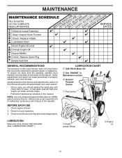
... the Service and Adjustments section of injury to service this manual. Check for wear. Check engine oil level. 2. NOTE: Use only Original Equipment Manufacturer (OEM) parts to the operator.
... the Service and Adjustments section of injury to service this manual. Check for wear. Check engine oil level. 2. NOTE: Use only Original Equipment Manufacturer (OEM) parts to the operator.

User Manual
Page 15
... of the above • 32°F. Pour slowly. MUFFLER Inspect and replace corroded muffler as it cannot come in contact with lubricant to your local parts dealer.
... of the above • 32°F. Pour slowly. MUFFLER Inspect and replace corroded muffler as it cannot come in contact with lubricant to your local parts dealer.

User Manual
Page 16
...turn when auger control lever is engaged, check to see if the capscrews have completely stopped. 4. Make sure the augers and all moving parts have sheared. Should a foreign object or ice become lodged in impeller shaft and install two (2) new 1/4-20 x 1-5/8" capscrew/shear bolts....the auger shaft with plug. 3. Connect spark plug wire to spark plug. Install 1/4-20 locknuts and tighten securely. Wait for all moving parts to STOP position. Remove safety ignition key. 3. Disengage all controls and move throttle control to stop . 2. Connect spark plug wire to ...
...turn when auger control lever is engaged, check to see if the capscrews have completely stopped. 4. Make sure the augers and all moving parts have sheared. Should a foreign object or ice become lodged in impeller shaft and install two (2) new 1/4-20 x 1-5/8" capscrew/shear bolts....the auger shaft with plug. 3. Connect spark plug wire to spark plug. Install 1/4-20 locknuts and tighten securely. Wait for all moving parts to STOP position. Remove safety ignition key. 3. Disengage all controls and move throttle control to stop . 2. Connect spark plug wire to ...
User Manual
Page 18
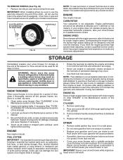
... appliance. sand lightly before storing in the wheel hub (if equipped). Replace with clean engine oil. (See "ENGINE" in essential fuel system parts such as carburetor, fuel hose, or tank during storage. ENGINE See engine manual. • Replace your gasoline can starts to protect it thoroughly...while in minimizing the formation of the season or if the unit will cause problems. FUEL SYSTEM • If possible, store your local parts dealer. Clean entire snow thrower (See "CLEANING" in your gasoline will not be purchased from axle. Run engine at altitudes up all ...
... appliance. sand lightly before storing in the wheel hub (if equipped). Replace with clean engine oil. (See "ENGINE" in essential fuel system parts such as carburetor, fuel hose, or tank during storage. ENGINE See engine manual. • Replace your gasoline can starts to protect it thoroughly...while in minimizing the formation of the season or if the unit will cause problems. FUEL SYSTEM • If possible, store your local parts dealer. Clean entire snow thrower (See "CLEANING" in your gasoline will not be purchased from axle. Run engine at altitudes up all ...
User Manual
Page 19
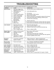
...Reconnect spark plug wire. 2. Blockage in FULL position. 2. Drain tank and refill with fresh gasoline. 5. Contact a qualified service center. Replace damaged parts. Check / replace drive belt. of power 1. Auger belt is not inserted. 3. Check / replace auger belt. 3. Remove debris or foreign object...center. Water in the Operation section of this manual. 7. Drain fuel tank and carburetor, refill tank with fresh, clean fuel. 4. Loose parts or damaged augers or impeller. 1. See "IF RECOIL STARTER HAS FROZEN" in fuel. 5. Friction drive wheel is flooded. 8. Clogged ...
...Reconnect spark plug wire. 2. Blockage in FULL position. 2. Drain tank and refill with fresh gasoline. 5. Contact a qualified service center. Replace damaged parts. Check / replace drive belt. of power 1. Auger belt is not inserted. 3. Check / replace auger belt. 3. Remove debris or foreign object...center. Water in the Operation section of this manual. 7. Drain fuel tank and carburetor, refill tank with fresh, clean fuel. 4. Loose parts or damaged augers or impeller. 1. See "IF RECOIL STARTER HAS FROZEN" in fuel. 5. Friction drive wheel is flooded. 8. Clogged ...
User Manual
Page 21
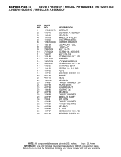
REPAIR PARTS SNOW THROWER - Failure to do so could be hazardous, damage your snow thrower and void your warranty. 21 MODEL PP10530ES (96192001802) AUGER HOUSING / IMPELLER ASSEMBLY KEY NO. 1 2 3 4 5 6 7 8 9 10 11 12 13 14 15 16 ...17 18 19 20 21 22 23 24 25 26 27 28 29 30 31 32 33 34 35 36 PART NO. 175321X479 196710...: All component dimensions given in U.S. inches. 1 inch = 25.4 mm IMPORTANT: Use only Original Equipment Manufacturer (O.E.M.) replacement parts.
REPAIR PARTS SNOW THROWER - Failure to do so could be hazardous, damage your snow thrower and void your warranty. 21 MODEL PP10530ES (96192001802) AUGER HOUSING / IMPELLER ASSEMBLY KEY NO. 1 2 3 4 5 6 7 8 9 10 11 12 13 14 15 16 ...17 18 19 20 21 22 23 24 25 26 27 28 29 30 31 32 33 34 35 36 PART NO. 175321X479 196710...: All component dimensions given in U.S. inches. 1 inch = 25.4 mm IMPORTANT: Use only Original Equipment Manufacturer (O.E.M.) replacement parts.
User Manual
Page 22
... to do so could be hazardous, damage your snow thrower and void your warranty. 22 REPAIR PARTS SNOW THROWER - MODEL PP10530ES (96192001802) AUGER HOUSING / IMPELLER ASSEMBLY 1 3 (5x) 4 (5x) 2 01.07.003-A KEY NO. 1 2 3 4 PART NO. 404930X428 404933X479 72270505 155377 DESCRIPTION AUGER HOUSING SCRAPPER BAR CARRIAGE BOLT 5/16−18 X .625 NUT 5/16−...
... to do so could be hazardous, damage your snow thrower and void your warranty. 22 REPAIR PARTS SNOW THROWER - MODEL PP10530ES (96192001802) AUGER HOUSING / IMPELLER ASSEMBLY 1 3 (5x) 4 (5x) 2 01.07.003-A KEY NO. 1 2 3 4 PART NO. 404930X428 404933X479 72270505 155377 DESCRIPTION AUGER HOUSING SCRAPPER BAR CARRIAGE BOLT 5/16−18 X .625 NUT 5/16−...

User Manual
Page 23
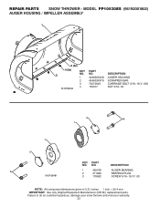
MODEL PP10530ES (96192001802) AUGER HOUSING / IMPELLER ASSEMBLY 3 4 3 01.11.001-A 1 4 2 KEY NO. 1 2 3 4 PART NO. 174762X479 178777X479 72270506 751153 DESCRIPTION SKID PLATE LH SKID PLATE RH CARRIAGE BOLT 5/16−18 X .75 NUT 5/16−18 2 1 KEY NO. 1 2 PART NO. 420497X479 420498X479 DESCRIPTION AUGER ASSEMBLY 30 LH AUGER ASSEMBLY 30 RH 01.07.019-A NOTE...
MODEL PP10530ES (96192001802) AUGER HOUSING / IMPELLER ASSEMBLY 3 4 3 01.11.001-A 1 4 2 KEY NO. 1 2 3 4 PART NO. 174762X479 178777X479 72270506 751153 DESCRIPTION SKID PLATE LH SKID PLATE RH CARRIAGE BOLT 5/16−18 X .75 NUT 5/16−18 2 1 KEY NO. 1 2 PART NO. 420497X479 420498X479 DESCRIPTION AUGER ASSEMBLY 30 LH AUGER ASSEMBLY 30 RH 01.07.019-A NOTE...
User Manual
Page 24
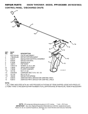
... LOOSE WITH PRODUCT. 2. NOTE: All component dimensions given in U.S. MODEL PP10530ES (96192001802) CONTROL PANEL / DISCHARGE CHUTE 5 7 14 3 15 *13 KEY NO. 1 2 3 4 5 6 7 *8 *9 *10 *11 *12 *13 14 15 PART NO. 404770X428 178633X428 420673 420325 414280 128415 17501010 179829 179246 191730 72250505 751153....625 SHOULDER SCREW PLASTIC WASHER NUT 1/4−20 CARRIAGE BOLT 5/16−18 X .50 NUT 5/16−18 DEFLECTOR SPRING (SERVICE PART) DEFLECTOR CONTROL HEAD (SERVICE PART) DEFLECTOR CONTROL CABLE *10 *9 *8 6 *12 *11 01.09.002-B NOTE: 1. inches. 1 inch = 25.4 mm IMPORTANT...
... LOOSE WITH PRODUCT. 2. NOTE: All component dimensions given in U.S. MODEL PP10530ES (96192001802) CONTROL PANEL / DISCHARGE CHUTE 5 7 14 3 15 *13 KEY NO. 1 2 3 4 5 6 7 *8 *9 *10 *11 *12 *13 14 15 PART NO. 404770X428 178633X428 420673 420325 414280 128415 17501010 179829 179246 191730 72250505 751153....625 SHOULDER SCREW PLASTIC WASHER NUT 1/4−20 CARRIAGE BOLT 5/16−18 X .50 NUT 5/16−18 DEFLECTOR SPRING (SERVICE PART) DEFLECTOR CONTROL HEAD (SERVICE PART) DEFLECTOR CONTROL CABLE *10 *9 *8 6 *12 *11 01.09.002-B NOTE: 1. inches. 1 inch = 25.4 mm IMPORTANT...
User Manual
Page 25
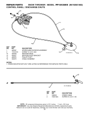
...PP10530ES (96192001802) CONTROL PANEL / DISCHARGE CHUTE 2 2 *3 1 *6 *6 KEY NO. 1 2 *3 *4 *5 *6 PART NO. 420337 17501010 420678 420677 420675 420674 DESCRIPTION LEVER/CABLE ROTATOR ASSEMBLY SCREW 10−24 X .625 ROTATOR HEAD ROTATOR PIVOT BRACKET PULLEY PIVOT CABLE ASSEMBLY *4 01.09.007-A *5 NOTES: 1. inches. 1 inch = 25.4 mm IMPORTANT: Use only Original Equipment Manufacturer (O.E.M.) replacement parts... void your warranty. 25 REPAIR PARTS SNOW THROWER - ITEMS INDICATED WITH AN * ARE LISTED AS REFERENCE FOR SERVICE PARTS ONLY. 2 1 KEY NO. 1 2 PART NO. 188303 74041024 01.15....
...PP10530ES (96192001802) CONTROL PANEL / DISCHARGE CHUTE 2 2 *3 1 *6 *6 KEY NO. 1 2 *3 *4 *5 *6 PART NO. 420337 17501010 420678 420677 420675 420674 DESCRIPTION LEVER/CABLE ROTATOR ASSEMBLY SCREW 10−24 X .625 ROTATOR HEAD ROTATOR PIVOT BRACKET PULLEY PIVOT CABLE ASSEMBLY *4 01.09.007-A *5 NOTES: 1. inches. 1 inch = 25.4 mm IMPORTANT: Use only Original Equipment Manufacturer (O.E.M.) replacement parts... void your warranty. 25 REPAIR PARTS SNOW THROWER - ITEMS INDICATED WITH AN * ARE LISTED AS REFERENCE FOR SERVICE PARTS ONLY. 2 1 KEY NO. 1 2 PART NO. 188303 74041024 01.15....

User Manual
Page 26
NO. REPAIR PARTS HANDLES SNOW THROWER - DESCRIPTION 1 412675X004 INTERLOCK SPRING 32 3 414572 178831 INTERLOCK CAM TORSION SPRING 4 169675 RETAINER 5 17060410 SCREW 1/4−20 X .625 6 421252 ...X 1.50 4 74780528 SCREW 5/16−18 X 1.75 5 751153 NUT 5/16−18 1 01.08.004-A 4 5 2 1 6 KEY PART NO. Failure to do so could be hazardous, damage your snow thrower and void your warranty. 26 MODEL PP10530ES (96192001802) 5 5 4 2 3 5 5 3 KEY PART 3 NO. inches. 1 inch = 25.4 mm IMPORTANT: Use only Original Equipment Manufacturer (O.E.M.) replacement...
NO. REPAIR PARTS HANDLES SNOW THROWER - DESCRIPTION 1 412675X004 INTERLOCK SPRING 32 3 414572 178831 INTERLOCK CAM TORSION SPRING 4 169675 RETAINER 5 17060410 SCREW 1/4−20 X .625 6 421252 ...X 1.50 4 74780528 SCREW 5/16−18 X 1.75 5 751153 NUT 5/16−18 1 01.08.004-A 4 5 2 1 6 KEY PART NO. Failure to do so could be hazardous, damage your snow thrower and void your warranty. 26 MODEL PP10530ES (96192001802) 5 5 4 2 3 5 5 3 KEY PART 3 NO. inches. 1 inch = 25.4 mm IMPORTANT: Use only Original Equipment Manufacturer (O.E.M.) replacement...


