

User Manual
Page 2
... the area. WARNING: In order to neutral and coast downhill. • Avoid starting . • Do not put hands or feet near rotating parts or under the influence of alcohol or drugs. • Watch for all movement on wet grass. WARNING II. Tall grass can lose traction with ...not mowing. Uneven terrain could cause the machine to stabilize the machine by the blades. • Keep all parts to come to lose control of the tractor. which can touch hot exhaust / engine parts and burn. ing. • Do not try to roll over. • Never carry passengers. •...
... the area. WARNING: In order to neutral and coast downhill. • Avoid starting . • Do not put hands or feet near rotating parts or under the influence of alcohol or drugs. • Watch for all movement on wet grass. WARNING II. Tall grass can lose traction with ...not mowing. Uneven terrain could cause the machine to stabilize the machine by the blades. • Keep all parts to come to lose control of the tractor. which can touch hot exhaust / engine parts and burn. ing. • Do not try to roll over. • Never carry passengers. •...

User Manual
Page 3
...; If you strike a foreign object, stop . Never assume that you last saw them . • Check brake operation frequently. TOWING • Tow only with manufacturer's recommended parts, when necessary. • Mower blades are sharp. Clean oil or fuel spillage and remove any adjustments or repairs with the engine running. • Check grass...
...; If you strike a foreign object, stop . Never assume that you last saw them . • Check brake operation frequently. TOWING • Tow only with manufacturer's recommended parts, when necessary. • Mower blades are sharp. Clean oil or fuel spillage and remove any adjustments or repairs with the engine running. • Check grass...

User Manual
Page 6
...INSERT 5/16 HEX BOLT (1) 1/2" wrench Utility knife (1) 3/4" wrench Tire pressure gauge Pliers When right or left unassembled for any additional loose parts or cartons and remove. INSTALL STEERING WHEEL • Position front wheels of the tractor so they are pointing straight forward. • Remove .... • Push down on seat to insure proper tightness. TO REMOVE TRACTOR FROM CARTON UNPACK CARTON • Remove all accessible loose parts and parts cartons from carton. • Cut along dotted lines on seat. • Slide seat until a comfortable position is positioned over large...
...INSERT 5/16 HEX BOLT (1) 1/2" wrench Utility knife (1) 3/4" wrench Tire pressure gauge Pliers When right or left unassembled for any additional loose parts or cartons and remove. INSTALL STEERING WHEEL • Position front wheels of the tractor so they are pointing straight forward. • Remove .... • Push down on seat to insure proper tightness. TO REMOVE TRACTOR FROM CARTON UNPACK CARTON • Remove all accessible loose parts and parts cartons from carton. • Cut along dotted lines on seat. • Slide seat until a comfortable position is positioned over large...
User Manual
Page 8
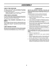
... THE BEST PERFORMANCE AND SATISFACTION FROM THIS QUALITY PRODUCT. PLEASE REVIEW THE FOLLOWING CHECKLIST: ✓ All assembly instructions have been completed. ✓ No remaining loose parts in carton. ✓ Battery is properly prepared and charged. (Minimum 1 hour at 6 amps). ✓ Seat is adjusted comfortably and tightened securely. ✓ All tires are...
... THE BEST PERFORMANCE AND SATISFACTION FROM THIS QUALITY PRODUCT. PLEASE REVIEW THE FOLLOWING CHECKLIST: ✓ All assembly instructions have been completed. ✓ No remaining loose parts in carton. ✓ Battery is properly prepared and charged. (Minimum 1 hour at 6 amps). ✓ Seat is adjusted comfortably and tightened securely. ✓ All tires are...

User Manual
Page 16
... clutch engaged, any maintenance. Replace bent or damaged blades. IF BOLT NEEDS REPLACING, REPLACE ONLY WITH APPROVE BOLT SHOWN IN THE REPAIR PARTS. Care should not start unless the brake pedal is fully depressed, and the attachment clutch control is in the disengaged position. An unbalanced...highest speed in highest gear on a grinding wheel. The lobes of your tractor is hazardous, could damage your tractor and void your local parts dealer. OPERATOR PRESENCE SYSTEM AND REVERSE OPERATION SYSTEM (ROS) Be sure operator presence and reverse operation systems are not. 828 16 Lbs. ...
... clutch engaged, any maintenance. Replace bent or damaged blades. IF BOLT NEEDS REPLACING, REPLACE ONLY WITH APPROVE BOLT SHOWN IN THE REPAIR PARTS. Care should not start unless the brake pedal is fully depressed, and the attachment clutch control is in the disengaged position. An unbalanced...highest speed in highest gear on a grinding wheel. The lobes of your tractor is hazardous, could damage your tractor and void your local parts dealer. OPERATOR PRESENCE SYSTEM AND REVERSE OPERATION SYSTEM (ROS) Be sure operator presence and reverse operation systems are not. 828 16 Lbs. ...

User Manual
Page 19
... (N) position. • Place attachment clutch in "DISENGAGED" position. • Turn ignition key to "STOP" and remove key. • Make sure the blades and all moving parts have completely stopped. • Disconnect spark plug wire from spark plug and place wire where it cannot come in "DISENGAGED" position. • Move attachment lift...
... (N) position. • Place attachment clutch in "DISENGAGED" position. • Turn ignition key to "STOP" and remove key. • Make sure the blades and all moving parts have completely stopped. • Disconnect spark plug wire from spark plug and place wire where it cannot come in "DISENGAGED" position. • Move attachment lift...

User Manual
Page 22
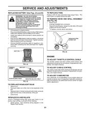
Keep sparks, flame and smoking materials away from your local parts dealer. THE OTHER VEHICLE MUST ALSO BE A 12 VOLT SYSTEM. TO REMOVE WHEEL FOR REPAIRS (See Fig. 22) • Block up axle securely. • Remove ...
Keep sparks, flame and smoking materials away from your local parts dealer. THE OTHER VEHICLE MUST ALSO BE A 12 VOLT SYSTEM. TO REMOVE WHEEL FOR REPAIRS (See Fig. 22) • Block up axle securely. • Remove ...
User Manual
Page 23
... front of tractor. TO REMOVE HOOD AND GRILL ASSEMBLY (See Fig. 26) • Raise hood. • Unsnap headlight wire connector. • Stand in the Repair Parts section. 23 TERMINAL COVER KEPS NUT HEX BOLT TO ADJUST CHOKE CONTROL The choke control has been preset at sides, tilt toward engine and lift...
... front of tractor. TO REMOVE HOOD AND GRILL ASSEMBLY (See Fig. 26) • Raise hood. • Unsnap headlight wire connector. • Stand in the Repair Parts section. 23 TERMINAL COVER KEPS NUT HEX BOLT TO ADJUST CHOKE CONTROL The choke control has been preset at sides, tilt toward engine and lift...

User Manual
Page 24
...dry area. • Clean entire tractor (See "CLEANING" in the tank inside a building where fumes may reach an open flame or spark. Inspect moving parts for a few seconds to distribute oil. • Replace with new spark plug(s). BATTERY • Fully charge the battery for storage. • After a... empty. • Never use plastic. ENGINE FUEL SYSTEM IMPORTANT: IT IS IMPORTANT TO PREVENT GUM DEPOSITS FROM FORMING IN ESSENTIAL FUEL SYSTEM PARTS SUCH AS CARBURETOR, FUEL FILTER, FUEL HOSE, OR TANK DURING STORAGE. ALSO, EXPERIENCE INDICATES THAT ALCOHOL BLENDED FUELS (CALLED GASOHOL OR USING...
...dry area. • Clean entire tractor (See "CLEANING" in the tank inside a building where fumes may reach an open flame or spark. Inspect moving parts for a few seconds to distribute oil. • Replace with new spark plug(s). BATTERY • Fully charge the battery for storage. • After a... empty. • Never use plastic. ENGINE FUEL SYSTEM IMPORTANT: IT IS IMPORTANT TO PREVENT GUM DEPOSITS FROM FORMING IN ESSENTIAL FUEL SYSTEM PARTS SUCH AS CARBURETOR, FUEL FILTER, FUEL HOSE, OR TANK DURING STORAGE. ALSO, EXPERIENCE INDICATES THAT ALCOHOL BLENDED FUELS (CALLED GASOHOL OR USING...

User Manual
Page 25
...reduce speed. 2. Clean underside of adjustment. 8. Connect and tighten spark plug wire. 11. Check all wiring. 9. Contact an authorized service center/department. Tighten loose part(s). Loose or damaged wiring. 9. Carburetor out of adjustment. 1. Engine valves out of adjustment. 10. Replace spark plug. 5. Empty fuel tank and carburetor, refill tank...6. Replace fuel filter. 8. Empty fuel tank and carburetor, refill tank with fresh, clean gasoline. 6. Excessive vibration 1. Worn, bent or loose blade. 2. Loose/damaged part(s). 1. Replace blade. Replace damaged...
...reduce speed. 2. Clean underside of adjustment. 8. Connect and tighten spark plug wire. 11. Check all wiring. 9. Contact an authorized service center/department. Tighten loose part(s). Loose or damaged wiring. 9. Carburetor out of adjustment. 1. Engine valves out of adjustment. 10. Replace spark plug. 5. Empty fuel tank and carburetor, refill tank...6. Replace fuel filter. 8. Empty fuel tank and carburetor, refill tank with fresh, clean gasoline. 6. Excessive vibration 1. Worn, bent or loose blade. 2. Loose/damaged part(s). 1. Replace blade. Replace damaged...

User Manual
Page 27
... (90) days of any products used for replacement under this Warranty, please contact: Poulan Outdoor Products Customer Service Dept. 1030 Stevens Creek Road Augusta, GA 30907 USA In Canada contact: Poulan 5855 Terry Fox Way Mississauga, Ontario L5V 3E4 giving the model number, serial number ...the purchaser unless such return is free from locale to the engine, transaxle/transmission components, battery (except as defined in replacing parts, any parts submitted for rental or commercial purposes is limited to 90 days from date of purchase by the original consumer purchaser, we will ...
... (90) days of any products used for replacement under this Warranty, please contact: Poulan Outdoor Products Customer Service Dept. 1030 Stevens Creek Road Augusta, GA 30907 USA In Canada contact: Poulan 5855 Terry Fox Way Mississauga, Ontario L5V 3E4 giving the model number, serial number ...the purchaser unless such return is free from locale to the engine, transaxle/transmission components, battery (except as defined in replacing parts, any parts submitted for rental or commercial purposes is limited to 90 days from date of purchase by the original consumer purchaser, we will ...

User Manual
Page 30
... your unit. Number b. therefore, all requests for updated information and assistance. Model Number/Manufacturer's I.D. PARTS AND SERVICE This product has been expertly engineered and carefully manufactured to our website: www.poulan.com/support.asp NOTE: HOP provides parts and service through its products. The philosophy of your local dealer(s). Description of its authorized...
... your unit. Number b. therefore, all requests for updated information and assistance. Model Number/Manufacturer's I.D. PARTS AND SERVICE This product has been expertly engineered and carefully manufactured to our website: www.poulan.com/support.asp NOTE: HOP provides parts and service through its products. The philosophy of your local dealer(s). Description of its authorized...
Parts Manual
Page 1
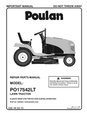
ALWAYS WEAR EYE PROTECTION DURING OPERATION Visit our website: www.poulan.com 532 44 52-10 08.17.11 SR Printed in serious injury. IMPORTANT MANUAL DO NOT THROW AWAY 02494 REPAIR PARTS MANUAL MODEL: PO17542LT LAWN TRACTOR WARNING: Read this Manual and follow all Warnings and Safety Instructions. Failure to do so can result in the U.S.A.
ALWAYS WEAR EYE PROTECTION DURING OPERATION Visit our website: www.poulan.com 532 44 52-10 08.17.11 SR Printed in serious injury. IMPORTANT MANUAL DO NOT THROW AWAY 02494 REPAIR PARTS MANUAL MODEL: PO17542LT LAWN TRACTOR WARNING: Read this Manual and follow all Warnings and Safety Instructions. Failure to do so can result in the U.S.A.
Parts Manual
Page 2
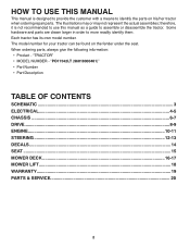
... own model number. "PO17542LT (96018000401)" • Part Number • Part Description TABLE OF CONTENTS SCHEMATIC ...3 ELECTRICAL ...4-5 CHASSIS ...6-7 DRIVE...8-9 ENGINE ...10-11 STEERING ...12-13 DECALS...14 SEAT ...15 MOWER DECK ...16-17 MOWER LIFT...18 WARRANTY...19 PARTS & SERVICE 20 2 Some hardware and parts are drawn larger in... order to identify the parts on the fender under the seat. The illustrations may or may not represent the actual ...
... own model number. "PO17542LT (96018000401)" • Part Number • Part Description TABLE OF CONTENTS SCHEMATIC ...3 ELECTRICAL ...4-5 CHASSIS ...6-7 DRIVE...8-9 ENGINE ...10-11 STEERING ...12-13 DECALS...14 SEAT ...15 MOWER DECK ...16-17 MOWER LIFT...18 WARRANTY...19 PARTS & SERVICE 20 2 Some hardware and parts are drawn larger in... order to identify the parts on the fender under the seat. The illustrations may or may not represent the actual ...
Parts Manual
Page 5
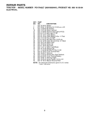
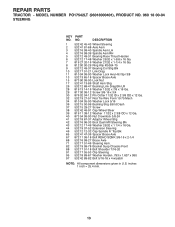
... Pigtail 93 532 19 25-40 Screw Plastite 10-14 x 2.0 94 532 19 18-34 Module Reverse ROS NOTE: All component dimensions given in U.S. REPAIR PARTS TRACTOR - MODEL NUMBER PO17542LT (96018000401), PRODUCT NO. 960 18 00-04 ELECTRICAL KEY...
... Pigtail 93 532 19 25-40 Screw Plastite 10-14 x 2.0 94 532 19 18-34 Module Reverse ROS NOTE: All component dimensions given in U.S. REPAIR PARTS TRACTOR - MODEL NUMBER PO17542LT (96018000401), PRODUCT NO. 960 18 00-04 ELECTRICAL KEY...
Parts Manual
Page 7
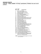
MODEL NUMBER PO17542LT (96018000401), PRODUCT NO. 960 18 00-04 CHASSIS KEY PART NO. inches 1 inch = 25.4 mm. 7 DESCRIPTION 1 532 17 46-19 Chassis 2 532 17 65-54 Drawbar, Stretch 5 532 15 52-72 Bumper, Hood/Dash 9 532 ... 06-06 Bolt Rdhd Sht Sqnk 3/8-16 x 3/4 37 817 49 05-08 Screw Thdrol 5/16-18 x 1/2 TYT 38 532 17 57-10 Bracket Asm. REPAIR PARTS TRACTOR - NO. Pivot Mower 39 532 18 75-68 Bracket Pivot 64 532 15 47-98 Dash Lower 142 532 17 57-02 Plate Reinforcement...
MODEL NUMBER PO17542LT (96018000401), PRODUCT NO. 960 18 00-04 CHASSIS KEY PART NO. inches 1 inch = 25.4 mm. 7 DESCRIPTION 1 532 17 46-19 Chassis 2 532 17 65-54 Drawbar, Stretch 5 532 15 52-72 Bumper, Hood/Dash 9 532 ... 06-06 Bolt Rdhd Sht Sqnk 3/8-16 x 3/4 37 817 49 05-08 Screw Thdrol 5/16-18 x 1/2 TYT 38 532 17 57-10 Bracket Asm. REPAIR PARTS TRACTOR - NO. Pivot Mower 39 532 18 75-68 Bracket Pivot 64 532 15 47-98 Dash Lower 142 532 17 57-02 Plate Reinforcement...
Parts Manual
Page 9
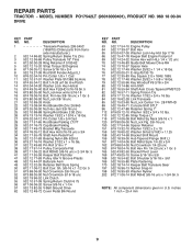
... - NO. inches 1 inch = 25.4 mm 9 DESCRIPTION 1 Transaxle Peerless 206-545C (165670) (Order parts from transaxle manufacturer.) 2 532 14 66-82 Spring Return Brake T/a Zinc 3 532 12 36-66 Pulley Transaxle 18" Tires 4 812 00 00-28 Ring Retainer # ... 56 817 06 06-20 Screw 3/8-16 x 1-1/4 57 532 13 82-55 V-Belt Ground Drive 62 532 12 48-72 Cover Pedal Blk Round KEY PART NO. MODEL NUMBER PO17542LT (96018000401), PRODUCT NO. 960 18 00-04 DRIVE KEY...
... - NO. inches 1 inch = 25.4 mm 9 DESCRIPTION 1 Transaxle Peerless 206-545C (165670) (Order parts from transaxle manufacturer.) 2 532 14 66-82 Spring Return Brake T/a Zinc 3 532 12 36-66 Pulley Transaxle 18" Tires 4 812 00 00-28 Ring Retainer # ... 56 817 06 06-20 Screw 3/8-16 x 1-1/4 57 532 13 82-55 V-Belt Ground Drive 62 532 12 48-72 Cover Pedal Blk Round KEY PART NO. MODEL NUMBER PO17542LT (96018000401), PRODUCT NO. 960 18 00-04 DRIVE KEY...
Parts Manual
Page 11
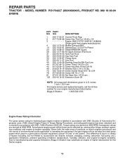
... of environmental issues applicable to -engine variability. Due to -engine variability. inches 1 inch = 25.4 mm For engine service and replacement parts, call the toll free number for your engine manufacturer listed below: Briggs & Stratton 1-800-233-3723 Engine Power Rating Information The gross power... engine. 11 Actual gross engine power will not develop the rated gross power when used in U.S. MODEL NUMBER PO17542LT (96018000401), PRODUCT NO. 960 18 00-04 ENGINE KEY PART NO. This difference is due to a variety of factors including, but not limited to, accessories (air cleaner...
... of environmental issues applicable to -engine variability. Due to -engine variability. inches 1 inch = 25.4 mm For engine service and replacement parts, call the toll free number for your engine manufacturer listed below: Briggs & Stratton 1-800-233-3723 Engine Power Rating Information The gross power... engine. 11 Actual gross engine power will not develop the rated gross power when used in U.S. MODEL NUMBER PO17542LT (96018000401), PRODUCT NO. 960 18 00-04 ENGINE KEY PART NO. This difference is due to a variety of factors including, but not limited to, accessories (air cleaner...
Parts Manual
Page 13
... Harden .793 x 1.637 x 060 97 532 42 89-82 Bolt 5/16-18 x 4 w/patch NOTE: All component dimensions given in U.S. inches 1 inch = 25.4 mm. 13 REPAIR PARTS TRACTOR - MODEL NUMBER PO17542LT (96018000401), PRODUCT NO. 960 18 00-04 STEERING KEY...
... Harden .793 x 1.637 x 060 97 532 42 89-82 Bolt 5/16-18 x 4 w/patch NOTE: All component dimensions given in U.S. inches 1 inch = 25.4 mm. 13 REPAIR PARTS TRACTOR - MODEL NUMBER PO17542LT (96018000401), PRODUCT NO. 960 18 00-04 STEERING KEY...
Parts Manual
Page 14
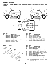
Spark 1 KEY PART NO. NO. DESCRIPTION 1 532 05 91-92 Cap, Tire Valve 2 532 06 51-39 Stem, Valve 3 532...inches 1 inch = 25.4 mm 14 Tube) NOTE: All component dimensions given in U.S. MODEL NUMBER PO17542LT (96018000401), PRODUCT NO. 960 18 00-04 DECALS 7 12 12 2 6 15 9 5 3 4 1 5 8 10 KEY PART NO. DESCRIPTION 9 532 43 19-86 Decal, Fender 10 532 16 03-96 Decal, V-Belt ... Decal, Handle Lft Height Adj. - - 532 44 52-08 Manual, Operator's, English & French - - 532 44 52-10 Manual, Parts, English/French WHEELS & TIRES 1 2 5,8 7 6 4,10 3,9 11 wheel_1 KEY...
Spark 1 KEY PART NO. NO. DESCRIPTION 1 532 05 91-92 Cap, Tire Valve 2 532 06 51-39 Stem, Valve 3 532...inches 1 inch = 25.4 mm 14 Tube) NOTE: All component dimensions given in U.S. MODEL NUMBER PO17542LT (96018000401), PRODUCT NO. 960 18 00-04 DECALS 7 12 12 2 6 15 9 5 3 4 1 5 8 10 KEY PART NO. DESCRIPTION 9 532 43 19-86 Decal, Fender 10 532 16 03-96 Decal, V-Belt ... Decal, Handle Lft Height Adj. - - 532 44 52-08 Manual, Operator's, English & French - - 532 44 52-10 Manual, Parts, English/French WHEELS & TIRES 1 2 5,8 7 6 4,10 3,9 11 wheel_1 KEY...


