

User Manual
Page 1
PO1538D 15 HP 38 Inch Lawn Tractor For Parts and Service, contact our authorized distributor: call 1-800-849-1297 For Technical Assistance: call 1-800-829-5886 187570 3.5.03 MH PRINTED IN U.S.A. MODEL NO.
PO1538D 15 HP 38 Inch Lawn Tractor For Parts and Service, contact our authorized distributor: call 1-800-849-1297 For Technical Assistance: call 1-800-829-5886 187570 3.5.03 MH PRINTED IN U.S.A. MODEL NO.
User Manual
Page 2
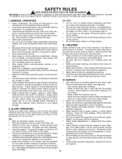
...regularly. running . Always look behind before turning. the machine and the mowing activity. IV. running . • Watch for wheel mended parts, when necessary. build-up to either the entire grass catcher or the guard in handling gasoline and other attachments. Do not allow responsible adults...slope. Always • Keep children out of grass, leaves, or other debris not smoke. Tall grass can touch hot exhaust / engine parts - Slopes are subject to be picked up and down slopes, not across. • Never make sudden changes in severe injury or ...
...regularly. running . Always look behind before turning. the machine and the mowing activity. IV. running . • Watch for wheel mended parts, when necessary. build-up to either the entire grass catcher or the guard in handling gasoline and other attachments. Do not allow responsible adults...slope. Always • Keep children out of grass, leaves, or other debris not smoke. Tall grass can touch hot exhaust / engine parts - Slopes are subject to be picked up and down slopes, not across. • Never make sudden changes in severe injury or ...
User Manual
Page 4
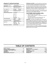
... RULES 2-3 PRODUCT SPECIFICATIONS 4 CUSTOMER RESPONSIBILITIES 4 ASSEMBLY 6-8 OPERATION 9-13 MAINTENANCE SCHEDULE 14 MAINTENANCE 14-18 SERVICE AND ADJUSTMENTS 19-23 STORAGE 24 TROUBLESHOOTING 25-26 REPAIR PARTS 28-41 WARRANTY 42 4 It has been designed, engineered and manufactured to give you cannot easily remedy, please contact your nearest authorized service center/department...
... RULES 2-3 PRODUCT SPECIFICATIONS 4 CUSTOMER RESPONSIBILITIES 4 ASSEMBLY 6-8 OPERATION 9-13 MAINTENANCE SCHEDULE 14 MAINTENANCE 14-18 SERVICE AND ADJUSTMENTS 19-23 STORAGE 24 TROUBLESHOOTING 25-26 REPAIR PARTS 28-41 WARRANTY 42 4 It has been designed, engineered and manufactured to give you cannot easily remedy, please contact your nearest authorized service center/department...
User Manual
Page 5
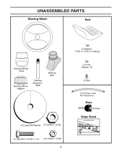
UNASSEMBLED PARTS Steering Wheel Seat Steering Wheel Insert Steering Wheel Adapter Steering Extension Shaft Steering Boot (1) Large Flat Washer (1) Locknut 1/2-20 (1) Hex Bolt 1/4-28 x 1-1/4 (1) Locknut 1/4-28 5 (1) Washer 17/32 x 1-3/16 x 12 Gauge (1) Lock Washer 1/2 (1) Bolt (1) Oil Drain Tube For Future Use Keys (2) Keys Slope Sheet
UNASSEMBLED PARTS Steering Wheel Seat Steering Wheel Insert Steering Wheel Adapter Steering Extension Shaft Steering Boot (1) Large Flat Washer (1) Locknut 1/2-20 (1) Hex Bolt 1/4-28 x 1-1/4 (1) Locknut 1/4-28 5 (1) Washer 17/32 x 1-3/16 x 12 Gauge (1) Lock Washer 1/2 (1) Bolt (1) Oil Drain Tube For Future Use Keys (2) Keys Slope Sheet
User Manual
Page 6
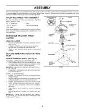
...slots in dash and push down to insure proper tightness. TO REMOVE TRACTOR FROM CARTON UNPACK CARTON • Remove all accessible loose parts and parts cartons from steering wheel and slide adapter onto steering shaft extension. • Position steering wheel so cross bars are horizontal (left... it means when you are pointing straight forward. • Remove steering wheel adapter from carton. • Cut along dotted lines on all parts and hardware you assemble must be tightened securely. Tighten securely. LBS TORQUE. • Place tabs of steering wheel. • Remove protective ...
...slots in dash and push down to insure proper tightness. TO REMOVE TRACTOR FROM CARTON UNPACK CARTON • Remove all accessible loose parts and parts cartons from steering wheel and slide adapter onto steering shaft extension. • Position steering wheel so cross bars are horizontal (left... it means when you are pointing straight forward. • Remove steering wheel adapter from carton. • Cut along dotted lines on all parts and hardware you assemble must be tightened securely. Tighten securely. LBS TORQUE. • Place tabs of steering wheel. • Remove protective ...
User Manual
Page 8
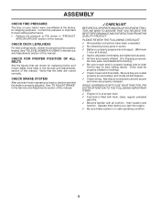
PLEASE REVIEW THE FOLLOWING CHECKLIST: ✓ All assembly instructions have been completed. ✓ No remaining loose parts in carton. ✓ Battery is properly prepared and charged. (Minimum 1 hour at the factory). ✓ Be sure mower deck is properly adjusted. Be sure they ...
PLEASE REVIEW THE FOLLOWING CHECKLIST: ✓ All assembly instructions have been completed. ✓ No remaining loose parts in carton. ✓ Battery is properly prepared and charged. (Minimum 1 hour at the factory). ✓ Be sure mower deck is properly adjusted. Be sure they ...
User Manual
Page 15
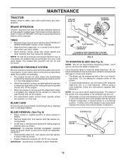
.... • The engine should not start unless the clutch/brake pedal is fully depressed and attachement clutch control is engaged, any maintenance. If your local parts dealer. Replace bent or damaged blades. TRAILING EDGE UP CENTER HOLE MANDREL ASSEMBLY LOCK WASHER STAR FLAT WASHER BLADE BOLT (GRADE 8)* BLADE *A GRADE 8 HEAT TREATED...
.... • The engine should not start unless the clutch/brake pedal is fully depressed and attachement clutch control is engaged, any maintenance. If your local parts dealer. Replace bent or damaged blades. TRAILING EDGE UP CENTER HOLE MANDREL ASSEMBLY LOCK WASHER STAR FLAT WASHER BLADE BOLT (GRADE 8)* BLADE *A GRADE 8 HEAT TREATED...

User Manual
Page 19
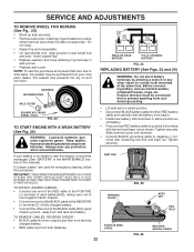
.... • Place flat washer and clutch spring on idler pulley bolt and secure with small retainer spring. • Install belt onto engine pulley. moving parts have completely stopped. • Disconnect spark plug wire from deck by re-
.... • Place flat washer and clutch spring on idler pulley bolt and secure with small retainer spring. • Install belt onto engine pulley. moving parts have completely stopped. • Disconnect spark plug wire from deck by re-
User Manual
Page 22
... RED battery cable and carefully remove battery from tractor. • Install new battery with terminals in axle groove. • Replace axle cover. If your local parts dealer. THE OTHER VEHICLE MUST ALSO BE A 12 VOLT SYSTEM. Before connecting battery, remove metal bracelets, wristwatch bands, rings, etc. Positive terminal must be connected...
... RED battery cable and carefully remove battery from tractor. • Install new battery with terminals in axle groove. • Replace axle cover. If your local parts dealer. THE OTHER VEHICLE MUST ALSO BE A 12 VOLT SYSTEM. Before connecting battery, remove metal bracelets, wristwatch bands, rings, etc. Positive terminal must be connected...
User Manual
Page 23
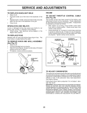
... connector. • Stand in fuse. damage may be required to fast position. • Check that holes "A" in governor control lever and hole in the Repair Parts section. INTERLOCKS AND RELAYS Loose or damaged wiring may cause your tractor to choke position. However, minor adjustment may result. IMPORTANT: NEVERTAMPERWITHTHEENGINEGOVERNOR, WHICH IS FACTORY...
... connector. • Stand in fuse. damage may be required to fast position. • Check that holes "A" in governor control lever and hole in the Repair Parts section. INTERLOCKS AND RELAYS Loose or damaged wiring may cause your tractor to choke position. However, minor adjustment may result. IMPORTANT: NEVERTAMPERWITHTHEENGINEGOVERNOR, WHICH IS FACTORY...
User Manual
Page 24
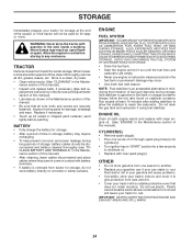
...engine or carburetor cleaner products in the fuel tank or permanent damage may occur. • Use fresh fuel next season. Inspect moving parts for damage, breakage and wear. Always follow the mix ratio found on concrete or damp surfaces. placement instructions in the Service and ...Be sure that does not retain moisture. ENGINE FUEL SYSTEM IMPORTANT: IT IS IMPORTANT TO PREVENT GUM DEPOSITS FROM FORMING IN ESSENTIAL FUEL SYSTEM PARTS SUCH AS CARBURETOR, FUEL FILTER, FUEL HOSE, OR TANK DURING STORAGE. IMPORTANT: NEVER COVERTRACTORWHILE ENGINE AND EXHAUST AREAS ARE STILL WARM. 24...
...engine or carburetor cleaner products in the fuel tank or permanent damage may occur. • Use fresh fuel next season. Inspect moving parts for damage, breakage and wear. Always follow the mix ratio found on concrete or damp surfaces. placement instructions in the Service and ...Be sure that does not retain moisture. ENGINE FUEL SYSTEM IMPORTANT: IT IS IMPORTANT TO PREVENT GUM DEPOSITS FROM FORMING IN ESSENTIAL FUEL SYSTEM PARTS SUCH AS CARBURETOR, FUEL FILTER, FUEL HOSE, OR TANK DURING STORAGE. IMPORTANT: NEVER COVERTRACTORWHILE ENGINE AND EXHAUST AREAS ARE STILL WARM. 24...
User Manual
Page 25
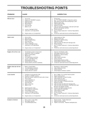
...of adjustment. 1. Loose or damaged wiring. 14. Replace fuel filter. 8. Worn, bent or loose blade. 2. Replace damaged parts. 25 Check all wiring. 7. Engine valves out of grass, leaves and trash under mower. 4. Recharge or replace battery. 4. Engine...wiring. 7. Loss of adjustment. 1. Clean underside of adjustment. 15. Check/replace ignition switch. 8. Carburetor out of mower housing. 4. Loose/damaged part(s). 1. Bad spark plug. 5. Corroded battery terminals. 3. Water in "CHOKE" position. 3. Excessive vibration 1. Stale or dirty fuel. 6. Adjust ...
...of adjustment. 1. Loose or damaged wiring. 14. Replace fuel filter. 8. Worn, bent or loose blade. 2. Replace damaged parts. 25 Check all wiring. 7. Engine valves out of grass, leaves and trash under mower. 4. Recharge or replace battery. 4. Engine...wiring. 7. Loss of adjustment. 1. Clean underside of adjustment. 15. Check/replace ignition switch. 8. Carburetor out of mower housing. 4. Loose/damaged part(s). 1. Bad spark plug. 5. Corroded battery terminals. 3. Water in "CHOKE" position. 3. Excessive vibration 1. Stale or dirty fuel. 6. Adjust ...

User Manual
Page 29
... 43 178861 Solenoid 48 140844 Adapter Ammeter 52 141940 Protection Wire Loop 90 180449 Cover Terminal Battery NOTE: All component dimensions given in U. NO. REPAIR PARTS TRACTOR - - MODEL NUMBER PO1538D ELECTRICAL KEY PART NO.
... 43 178861 Solenoid 48 140844 Adapter Ammeter 52 141940 Protection Wire Loop 90 180449 Cover Terminal Battery NOTE: All component dimensions given in U. NO. REPAIR PARTS TRACTOR - - MODEL NUMBER PO1538D ELECTRICAL KEY PART NO.
User Manual
Page 31
... 72110606 Bolt Rdhd Sht Sqnk 3/8-16 X3/4 37 17490508 Screw Thdrol 5/16-18 x 1/2 TYT 38 175710 Bracket Asm. inches 1 inch = 25.4 mm. 31 NO. REPAIR PARTS TRACTOR - - MODEL NUMBER PO1538D CHASSIS KEY PART NO.
... 72110606 Bolt Rdhd Sht Sqnk 3/8-16 X3/4 37 17490508 Screw Thdrol 5/16-18 x 1/2 TYT 38 175710 Bracket Asm. inches 1 inch = 25.4 mm. 31 NO. REPAIR PARTS TRACTOR - - MODEL NUMBER PO1538D CHASSIS KEY PART NO.
User Manual
Page 33
... 1-3/4 Gr.5 Nut Hex Flg Lock Screw 3/8-16 x 3/4 NOTE: All component dimensions given in U.S. REPAIR PARTS TRACTOR - - NO. DESCRIPTION 48 154407 49 123205X 50 72110612 51 73680600 52 73680500 53 105710X 55 105709X ... 19211616 37 1572H 38 179114 39 74760648 41 175556 47 127783 DESCRIPTION Transaxle Dana Model D4360-139 (Order parts from transaxle manufacturer) Spring Return Brake Pulley Transaxle 18"tires Ring Retainer # 5100-62 Strap Torque 30 ... Composite Flat Bolt Fin Hex 3/8-16 x 3 Keeper Belt Idler Pulley Idler V Groove Plastic KEY PART NO. MODEL NUMBER PO1538D DRIVE KEY PART NO.
... 1-3/4 Gr.5 Nut Hex Flg Lock Screw 3/8-16 x 3/4 NOTE: All component dimensions given in U.S. REPAIR PARTS TRACTOR - - NO. DESCRIPTION 48 154407 49 123205X 50 72110612 51 73680600 52 73680500 53 105710X 55 105709X ... 19211616 37 1572H 38 179114 39 74760648 41 175556 47 127783 DESCRIPTION Transaxle Dana Model D4360-139 (Order parts from transaxle manufacturer) Spring Return Brake Pulley Transaxle 18"tires Ring Retainer # 5100-62 Strap Torque 30 ... Composite Flat Bolt Fin Hex 3/8-16 x 3 Keeper Belt Idler Pulley Idler V Groove Plastic KEY PART NO. MODEL NUMBER PO1538D DRIVE KEY PART NO.
User Manual
Page 34
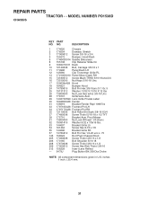
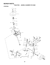
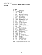
REPAIR PARTS TRACTOR - - MODEL NUMBER PO1538D STEERING 38 12 39 1 37 44 51 91 43 41 42 37 36 54 88 71 68 29 15 15 82 15 29 46 8 6 17 9 2 7 9 5 3 40 29 68 67 67 47 13 65 85 85 32 11 26 67 46 8 6 9 47 7 9 5 4 43 28 10 30 43 6 8 34
REPAIR PARTS TRACTOR - - MODEL NUMBER PO1538D STEERING 38 12 39 1 37 44 51 91 43 41 42 37 36 54 88 71 68 29 15 15 82 15 29 46 8 6 17 9 2 7 9 5 3 40 29 68 67 67 47 13 65 85 85 32 11 26 67 46 8 6 9 47 7 9 5 4 43 28 10 30 43 6 8 34
User Manual
Page 35
... Chassis Front 85 133835 Fastener Christmas Tree 88 175118 Bolt Shoulder 7/16-20 91 175553 Clip Steering NOTE: All component dimensions given in U.S. MODEL NUMBER PO1538D STEERING KEY PART NO. REPAIR PARTS TRACTOR - -
... Chassis Front 85 133835 Fastener Christmas Tree 88 175118 Bolt Shoulder 7/16-20 91 175553 Clip Steering NOTE: All component dimensions given in U.S. MODEL NUMBER PO1538D STEERING KEY PART NO. REPAIR PARTS TRACTOR - -

User Manual
Page 36
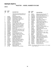
... 14 148456 16 11050600 23 169837 29 137180 31 184900 32 140527 DESCRIPTION Control Th/ch Flag Screw Hex Thd Cut 1/4-20 x 1/2 Engine, B&S 282H07 (Order parts from engine manufacturer) Muffler Exhaust B&S Gasket Eng 1 313 Id Tin Plated Tube Drain Oil Easy Washer Lock Ext Tooth 3/8 Shield BRN/DBR Guard... Kit Spark Arrestor (Flat Scrn) Tank Fuel Front Cap Asm Fuel KEY PART NO. MODEL NUMBER PO1538D ENGINE 2 3 72 1 81 13 4 78 38 32 14 16 44 78 46 33 31 37 33 40 45 29 23 OPTIONAL EQUIPMENT Spark...
... 14 148456 16 11050600 23 169837 29 137180 31 184900 32 140527 DESCRIPTION Control Th/ch Flag Screw Hex Thd Cut 1/4-20 x 1/2 Engine, B&S 282H07 (Order parts from engine manufacturer) Muffler Exhaust B&S Gasket Eng 1 313 Id Tin Plated Tube Drain Oil Easy Washer Lock Ext Tooth 3/8 Shield BRN/DBR Guard... Kit Spark Arrestor (Flat Scrn) Tank Fuel Front Cap Asm Fuel KEY PART NO. MODEL NUMBER PO1538D ENGINE 2 3 72 1 81 13 4 78 38 32 14 16 44 78 46 33 31 37 33 40 45 29 23 OPTIONAL EQUIPMENT Spark...
User Manual
Page 37
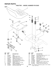
... Seat Cprsn 2 250 Blk Zi Screw 3/8-16 x 1.5 Washer 13/32 X 1 X 14 Ga Pan Pnt Seat (Blk) Bracket Pnt Mounting Switch Bushing Snap Blk Nyl 4 3 KEY PART NO. REPAIR PARTS TRACTOR - - MODEL NUMBER PO1538D SEAT 1 8 9 14 7 10 24 26 16 15 5 25 23 8 9 7 5 6 22 2 21 13 17 12 KEY NO. 1 2 3 4 5 6 7 8 9 10 12 13...
... Seat Cprsn 2 250 Blk Zi Screw 3/8-16 x 1.5 Washer 13/32 X 1 X 14 Ga Pan Pnt Seat (Blk) Bracket Pnt Mounting Switch Bushing Snap Blk Nyl 4 3 KEY PART NO. REPAIR PARTS TRACTOR - - MODEL NUMBER PO1538D SEAT 1 8 9 14 7 10 24 26 16 15 5 25 23 8 9 7 5 6 22 2 21 13 17 12 KEY NO. 1 2 3 4 5 6 7 8 9 10 12 13...

User Manual
Page 38
NO. Manual, Owner's English Manual, Owner's French WHEELS & TIRES 1 2 5,8 4,10 7 6 KEY PART NO. MODEL NUMBER PO1538D DECALS 8 7 12 2 14 9 6 8 15 16 4 3 KEY PART NO. NO. 1 181251 2 187580 3 184768 4 170563 6 157140 7 158168 8 172200 9 158166 1 17 DESCRIPTION Decal...- 187571 DESCRIPTION Decal, Hood RH Decal, Hood LH Decal, Caution, Battery Decal, Oper Sdl P/L Gear Dr Eng Decal, V-Belt Sch. Decal Fender KEY PART NO. DESCRIPTION 1 59192 Cap, Tire valve 2 65139 Stem, Valve 3 106222X Tire, Front 4 59904 Tube, Front (Service item only) 5 106732X624 Rim assembly...
NO. Manual, Owner's English Manual, Owner's French WHEELS & TIRES 1 2 5,8 4,10 7 6 KEY PART NO. MODEL NUMBER PO1538D DECALS 8 7 12 2 14 9 6 8 15 16 4 3 KEY PART NO. NO. 1 181251 2 187580 3 184768 4 170563 6 157140 7 158168 8 172200 9 158166 1 17 DESCRIPTION Decal...- 187571 DESCRIPTION Decal, Hood RH Decal, Hood LH Decal, Caution, Battery Decal, Oper Sdl P/L Gear Dr Eng Decal, V-Belt Sch. Decal Fender KEY PART NO. DESCRIPTION 1 59192 Cap, Tire valve 2 65139 Stem, Valve 3 106222X Tire, Front 4 59904 Tube, Front (Service item only) 5 106732X624 Rim assembly...


