
User Manual
Page 2
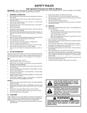
... extra care when loading or unloading the machine into a trailer or truck. Tall grass can result in reverse unless absolutely necessary. The mower could expose moving parts or allow objects to be seriously injured or interfere with safe machine operation. • Never allow responsible adults, ...• Keep machine free of the machine. • Keep all instructions in handling gasoline and other attachments. Look for Ride-On Mowers IMPORTANT: THIS CUTTING MACHINE IS CAPABLE OF AMPUTATING HANDS AND FEET AND THROWING OBJECTS. DO: • Mow up and down for traf...
... extra care when loading or unloading the machine into a trailer or truck. Tall grass can result in reverse unless absolutely necessary. The mower could expose moving parts or allow objects to be seriously injured or interfere with safe machine operation. • Never allow responsible adults, ...• Keep machine free of the machine. • Keep all instructions in handling gasoline and other attachments. Look for Ride-On Mowers IMPORTANT: THIS CUTTING MACHINE IS CAPABLE OF AMPUTATING HANDS AND FEET AND THROWING OBJECTS. DO: • Mow up and down for traf...

User Manual
Page 4
...Assembly 6-9 B Battery: Charging 7 Cleaning 17 Starting with Weak Battery 23 Storage 26 Terminals 17 Belt: Motion Drive Removal/Replacement 22 Mower Belt(s) Removal/Replacement 22 Blade: Sharpening 16 Replacement 16 Brake Adjustment 22 C Carburetor Adjustment 25 Controls, Tractor 11 Customer Responsibilities 15-... 14 Muffler 19 Spark Arrester 3,40 O Oil: Cold Weather Conditions 13,17 Engine 17 Storage 26 Operation 11-14 Operating Mower 13 Options: Spark Arrester 3,40 P Parking Brake 11-12 Parts Bag 5 Parts, Replacement/Repair 30-47 Product Specifications 3...
...Assembly 6-9 B Battery: Charging 7 Cleaning 17 Starting with Weak Battery 23 Storage 26 Terminals 17 Belt: Motion Drive Removal/Replacement 22 Mower Belt(s) Removal/Replacement 22 Blade: Sharpening 16 Replacement 16 Brake Adjustment 22 C Carburetor Adjustment 25 Controls, Tractor 11 Customer Responsibilities 15-... 14 Muffler 19 Spark Arrester 3,40 O Oil: Cold Weather Conditions 13,17 Engine 17 Storage 26 Operation 11-14 Operating Mower 13 Options: Spark Arrester 3,40 P Parking Brake 11-12 Parts Bag 5 Parts, Replacement/Repair 30-47 Product Specifications 3...
User Manual
Page 8
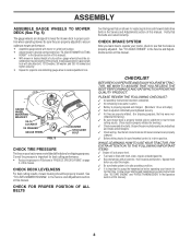
... wheel in the Service and Adjustments section of this manual. Be sure they are slightly off the ground. ASSEMBLY ASSEMBLE GAUGE WHEELS TO MOWER DECK (See Fig. 5) The gauge wheels are routed correctly. sembled so they are routed properly around pulleys and inside all connections are...;ated for the first time. CHECK FOR PROPER POSITION OF ALL BELTS See the figures that the belts are designed to ensure optimum mower performance. • Assemble gauge wheels with shoulder bolt, 17/32 washer, 3/8 washer, and 3/8-16 locknut and tighten securely. • Repeat for ...
... wheel in the Service and Adjustments section of this manual. Be sure they are slightly off the ground. ASSEMBLY ASSEMBLE GAUGE WHEELS TO MOWER DECK (See Fig. 5) The gauge wheels are routed correctly. sembled so they are routed properly around pulleys and inside all connections are...;ated for the first time. CHECK FOR PROPER POSITION OF ALL BELTS See the figures that the belts are designed to ensure optimum mower performance. • Assemble gauge wheels with shoulder bolt, 17/32 washer, 3/8 washer, and 3/8-16 locknut and tighten securely. • Repeat for ...

User Manual
Page 9
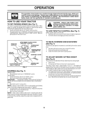
BATTERY CAUTION OR WARNING REVERSE FORWARD FAST SLOW ENGINE ON ENGINE OFF OIL PRESSURE CLUTCH LIGHTS ON LIGHTS OFF FUEL CHOKE MOWER HEIGHT DIFFERENTIAL PARKING BRAKE LOCK LOCKED UNLOCKED REVERSE NEUTRAL HIGH LOW P PARKING BRAKE MOWER LIFT ATTACHMENT CLUTCH ENGAGED ATTACHMENT CLUTCH DISENGAGED IGNITION DANGER, KEEP HANDS AND FEET AWAY 9 HYDROSTATIC FREE WHEEL (Hydro Models only) OPERATION These symbols may appear on your tractor or in literature supplied with the product. Learn and understand their meaning.
BATTERY CAUTION OR WARNING REVERSE FORWARD FAST SLOW ENGINE ON ENGINE OFF OIL PRESSURE CLUTCH LIGHTS ON LIGHTS OFF FUEL CHOKE MOWER HEIGHT DIFFERENTIAL PARKING BRAKE LOCK LOCKED UNLOCKED REVERSE NEUTRAL HIGH LOW P PARKING BRAKE MOWER LIFT ATTACHMENT CLUTCH ENGAGED ATTACHMENT CLUTCH DISENGAGED IGNITION DANGER, KEEP HANDS AND FEET AWAY 9 HYDROSTATIC FREE WHEEL (Hydro Models only) OPERATION These symbols may appear on your tractor or in literature supplied with the product. Learn and understand their meaning.

User Manual
Page 10
...CHOKE CONTROL - PARKING BRAKE: Locks clutch/brake pedal into the brake position. ATTACHMENT CLUTCH LEVER: Used to engage the mower blades, or other attachments mounted to your tractor. Disengages transmission for declutching and braking the tractor and starting and control-... ATTACHMENT CLUTCH LEVER LIGHT SWITCH POSITION THROTTLE/CHOKE CONTROL IGNITION SWITCH LIFT LEVER PLUNGER CLUTCH/ BRAKE PEDAL ATTACHMENT LIFT LEVER MOWER HEIGHT ADJUSTMENT POSTITIONS PARKING BRAKE FREEWHEEL CONTROL MOTION CONTROL LEVER FIG. 6 Our tractors conform to the safety standards of ...
...CHOKE CONTROL - PARKING BRAKE: Locks clutch/brake pedal into the brake position. ATTACHMENT CLUTCH LEVER: Used to engage the mower blades, or other attachments mounted to your tractor. Disengages transmission for declutching and braking the tractor and starting and control-... ATTACHMENT CLUTCH LEVER LIGHT SWITCH POSITION THROTTLE/CHOKE CONTROL IGNITION SWITCH LIFT LEVER PLUNGER CLUTCH/ BRAKE PEDAL ATTACHMENT LIFT LEVER MOWER HEIGHT ADJUSTMENT POSTITIONS PARKING BRAKE FREEWHEEL CONTROL MOTION CONTROL LEVER FIG. 6 Our tractors conform to the safety standards of ...
User Manual
Page 11
... Operating engine at less than full throttle reduces the battery charging rate. • Full throttle offers the best bagging and mower performance. ENGINE • Move throttle control to desired height. 11 For healthier and better looking lawns, mow often and ...DISENGAGED" POSITION PARKING BRAKE "ENGAGED" POSITION GEARSHIFT LEVER CLUTCH/BRAKE PEDAL "DRIVE" POSITION FIG. 7 "DISENGAGED" POSITION STOPPING (See Fig. 7) MOWER BLADES • Move attachment clutch lever to empty grass catcher, etc. NOTE: Under certain conditions when tractor is approximately 1-1/2 to neutral (N)...
... Operating engine at less than full throttle reduces the battery charging rate. • Full throttle offers the best bagging and mower performance. ENGINE • Move throttle control to desired height. 11 For healthier and better looking lawns, mow often and ...DISENGAGED" POSITION PARKING BRAKE "ENGAGED" POSITION GEARSHIFT LEVER CLUTCH/BRAKE PEDAL "DRIVE" POSITION FIG. 7 "DISENGAGED" POSITION STOPPING (See Fig. 7) MOWER BLADES • Move attachment clutch lever to empty grass catcher, etc. NOTE: Under certain conditions when tractor is approximately 1-1/2 to neutral (N)...

User Manual
Page 12
... the engine running and the attachment clutch engaged will shut off the engine. • Select desired height of cut. • Lower mower with an operator presence sensing switch. IMPORTANT: THE MOTION CONTROL LEVER DOES NOT RETURN TO NEUTRAL (N) POSITION WHEN THE CLUTCH/BRAKE PEDAL ... Your tractor is equipped with attachment lift control. • Start mower blades by engaging attachment clutch control. • TO STOP MOWER BLADES - CAUTION: Do not operate the mower without either the entire grass catcher, on mowers so equipped, or the discharge guard in position by inserting retainer ...
... the engine running and the attachment clutch engaged will shut off the engine. • Select desired height of cut. • Lower mower with an operator presence sensing switch. IMPORTANT: THE MOTION CONTROL LEVER DOES NOT RETURN TO NEUTRAL (N) POSITION WHEN THE CLUTCH/BRAKE PEDAL ... Your tractor is equipped with attachment lift control. • Start mower blades by engaging attachment clutch control. • TO STOP MOWER BLADES - CAUTION: Do not operate the mower without either the entire grass catcher, on mowers so equipped, or the discharge guard in position by inserting retainer ...

User Manual
Page 14
...tall, it should be purged before mowing. • Always operate engine at full throttle when mowing to neutral (N) position. See "TO LEVEL MOWER HOUSING" in the tractor seat, start by selecting a low enough gear to full forward position and hold for trimming. • Drive so...second to the right so that the transmission be used . Have the cut relatively high; After the engine is recommended that clippings will plug mower and leave undesirable clumps. To ensure proper operation and performance, it is run- Repeat this manual. • The left hand turns until ...
...tall, it should be purged before mowing. • Always operate engine at full throttle when mowing to neutral (N) position. See "TO LEVEL MOWER HOUSING" in the tractor seat, start by selecting a low enough gear to full forward position and hold for trimming. • Drive so...second to the right so that the transmission be used . Have the cut relatively high; After the engine is recommended that clippings will plug mower and leave undesirable clumps. To ensure proper operation and performance, it is run- Repeat this manual. • The left hand turns until ...

User Manual
Page 15
... tractor. BEFORE EACH USE • Check engine oil level. • Check brake operation. • Check tire pressure. • Check for Loose Fasteners ✔ R Sharpen/Replace Mower Blades A C Lubrication Chart T Check Battery Level/Recharge 0 Clean Battery and Terminals ✔7 ✔ ✔4 ✔ ✔ ✔6 ✔ ✔ R Check Transaxle Cooling ✔ Adjust Blade...
... tractor. BEFORE EACH USE • Check engine oil level. • Check brake operation. • Check tire pressure. • Check for Loose Fasteners ✔ R Sharpen/Replace Mower Blades A C Lubrication Chart T Check Battery Level/Recharge 0 Clean Battery and Terminals ✔7 ✔ ✔4 ✔ ✔ ✔6 ✔ ✔ R Check Transaxle Cooling ✔ Adjust Blade...

User Manual
Page 16
... TREATED BOLT CAN BE IDENTIFIED BY SIX LINES ON THE BOLT HEAD. NOTE: Do not use . BLADE REMOVAL (See Fig. 11) • Raise mower to highest position to allow access to an unthreaded portion of the blade moves downward, sharpen the heavy end until bright. • Coat terminals with... grease or petroleum jelly. • Reinstall battery (See "CONNECT BATTERY" in a horizontal position. Do not attempt to sharpen while on the mower. • To check blade balance, you do not recommend sharpening blade - If either end of the steel bolt or pin and hold the BLADE ...
... TREATED BOLT CAN BE IDENTIFIED BY SIX LINES ON THE BOLT HEAD. NOTE: Do not use . BLADE REMOVAL (See Fig. 11) • Raise mower to highest position to allow access to an unthreaded portion of the blade moves downward, sharpen the heavy end until bright. • Coat terminals with... grease or petroleum jelly. • Reinstall battery (See "CONNECT BATTERY" in a horizontal position. Do not attempt to sharpen while on the mower. • To check blade balance, you do not recommend sharpening blade - If either end of the steel bolt or pin and hold the BLADE ...
User Manual
Page 20
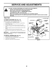
...removing retainer springs. • Disconnect front links from deck by removing retainer springs. • Raise lift lever to raise suspension arms. Slide mower out from the right side of tractor. • Place attachment clutch in reverse order of tractor. • Lower lift lever to its ...RETAINER SPRINGS (BOTH SIDES) FIG. 17 CLUTCH LEVER RETAINER SPRING ENGINE PULLEY RETAINER SPRINGS (BOTH SIDES) 20 TRACTOR TO REMOVE MOWER (See Fig. 17) Mower will be easier to remove from under tractor with plug. SERVICE AND ADJUSTMENTS CAUTION: BEFORE PERFORMING ANY SERVICE OR ADJUSTMENTS: •...
...removing retainer springs. • Disconnect front links from deck by removing retainer springs. • Raise lift lever to raise suspension arms. Slide mower out from the right side of tractor. • Place attachment clutch in reverse order of tractor. • Lower lift lever to its ...RETAINER SPRINGS (BOTH SIDES) FIG. 17 CLUTCH LEVER RETAINER SPRING ENGINE PULLEY RETAINER SPRINGS (BOTH SIDES) 20 TRACTOR TO REMOVE MOWER (See Fig. 17) Mower will be easier to remove from under tractor with plug. SERVICE AND ADJUSTMENTS CAUTION: BEFORE PERFORMING ANY SERVICE OR ADJUSTMENTS: •...

User Manual
Page 21
...nut "E" on both front links an equal number of turns. • When distance "D" is 1/8" to its highest position. BOTTOM EDGE OF MOWER TO GROUND BOTTOM EDGE OF MOWER TO GROUND Check adjustment on level ground or driveway. A GROUND LINE A FIG. 18 SUSPENSION ARM MANDREL "D" "D" FIG. 20 BOTH FRONT... as shown. • Before making any necessary adjustments, check that both front links. • To raise front of mower, loosen nut "F" from bottom edge of mower to -side adjustment. IF THE FOLLOWING FRONT-TO-BACK ADJUSTMENT IS NECESSARY, BE SURE TO ADJUST BOTH FRONT LINKS EQUALLY ...
...nut "E" on both front links an equal number of turns. • When distance "D" is 1/8" to its highest position. BOTTOM EDGE OF MOWER TO GROUND BOTTOM EDGE OF MOWER TO GROUND Check adjustment on level ground or driveway. A GROUND LINE A FIG. 18 SUSPENSION ARM MANDREL "D" "D" FIG. 20 BOTH FRONT... as shown. • Before making any necessary adjustments, check that both front links. • To raise front of mower, loosen nut "F" from bottom edge of mower to -side adjustment. IF THE FOLLOWING FRONT-TO-BACK ADJUSTMENT IS NECESSARY, BE SURE TO ADJUST BOTH FRONT LINKS EQUALLY ...
User Manual
Page 22
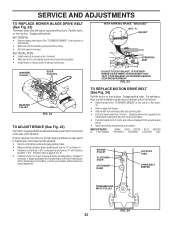
...nearest authorized service center/department. For assistance, there is a belt installation guide decal on bottom side of left footrest. • Remove mower (See "TO REMOVE MOWER" in this section of this manual.) • Remove upper belt keeper. • Remove belt from stationary idler and clutching idler.... on the side of this manual). • Work belt off both mandrel pulleys and idler pulleys. • Pull belt away from mower. IMPORTANT: MAKE SURE UPPER BELT KEEPER IS POSITIONED PROPERLY BETWEEN LOCATOR TAB. Retighten jam nut against nut "A". • Road test tractor...
...nearest authorized service center/department. For assistance, there is a belt installation guide decal on bottom side of left footrest. • Remove mower (See "TO REMOVE MOWER" in this section of this manual.) • Remove upper belt keeper. • Remove belt from stationary idler and clutching idler.... on the side of this manual). • Work belt off both mandrel pulleys and idler pulleys. • Pull belt away from mower. IMPORTANT: MAKE SURE UPPER BELT KEEPER IS POSITIONED PROPERLY BETWEEN LOCATOR TAB. Retighten jam nut against nut "A". • Road test tractor...

User Manual
Page 26
...8. Replace blade.Tighten blade bolt. 2. Dirty fuel filter. 7. Loose or damaged wiring. 9. Engine valves out of grass, leaves and trash under mower. 4. Corroded battery terminals. 6. Build-up of adjustment. Dirty fuel filter. 8. Bent blade mandrel. 3. Fill fuel tank. 2. See "TO...fresh gasoline. 6. Clean engine air screen/fins. 12. Tighten loose part(s). Water in Service Adjustments section. 8. Carburetor out of mower housing. 4. Dirty fuel filter. 5. Attachment clutch is engaged. 3. Faulty operator presence switch(es). Faulty solenoid or starter. ...
...8. Replace blade.Tighten blade bolt. 2. Dirty fuel filter. 7. Loose or damaged wiring. 9. Engine valves out of grass, leaves and trash under mower. 4. Corroded battery terminals. 6. Build-up of adjustment. Dirty fuel filter. 8. Bent blade mandrel. 3. Fill fuel tank. 2. See "TO...fresh gasoline. 6. Clean engine air screen/fins. 12. Tighten loose part(s). Water in Service Adjustments section. 8. Carburetor out of mower housing. 4. Dirty fuel filter. 5. Attachment clutch is engaged. 3. Faulty operator presence switch(es). Faulty solenoid or starter. ...

User Manual
Page 27
.... If not corrected, contact an authorized service center/ department. 1. Tighten blade bolt. 2. Clean around mandrels. Replace idler pulley. 4. Level mower deck. 5. Tighten blade bolt. 7. Turn switch "ON". 2. Replace bulb(s). 3. Replace regulator. 4. Purge transmission. 1. Faulty operator-safety ...Check/replace light switch. 4. Replace fuse. 1. Check/clean all connections. 3. Replace motion drive belt. 3. Buildup of mower housing. 4. Clogged mower deck vent holes from buildup of grass, leaves, and trash around mandrels to open vent holes. 1. Frozen idler pulley....
.... If not corrected, contact an authorized service center/ department. 1. Tighten blade bolt. 2. Clean around mandrels. Replace idler pulley. 4. Level mower deck. 5. Tighten blade bolt. 7. Turn switch "ON". 2. Replace bulb(s). 3. Replace regulator. 4. Purge transmission. 1. Faulty operator-safety ...Check/replace light switch. 4. Replace fuse. 1. Check/clean all connections. 3. Replace motion drive belt. 3. Buildup of mower housing. 4. Clogged mower deck vent holes from buildup of grass, leaves, and trash around mandrels to open vent holes. 1. Frozen idler pulley....

User Manual
Page 34
... 71070516 106 74780520 108 17541026 109145098 116 72110610 118 154774 121 154419 DESCRIPTION Bolt Hex 7/16 x 4 Gr. 5 Washer Keeper, Belt Engine Screw Guide, Belt, Mower Drive RH Strap, Torque, Lh Washer 13/32 x 1-1/4 x 12 Ga. Strap, Torque, Rh Spacer, Split Washer 25/32 x 1-1/4 x 16 Ga....24 x 1-5/8 Adaptor Fan Hydro Lt Hyd Alum Bolt Carriage 3/8-16 x 1.25 Spacer, Bellcrank Nyliner, Clutching Stl NOTE: All component dimensions give in U.S. MODEL NUMBER HD145H42G DRIVE KEY PART NO. Asm, Shaft Spring, Torsion Washer 17/32 x 3/4 x 16 Ga. Blk. Pin, Cotter 1/8 x 3/4 Rod, Parking Brake Cap, ...
... 71070516 106 74780520 108 17541026 109145098 116 72110610 118 154774 121 154419 DESCRIPTION Bolt Hex 7/16 x 4 Gr. 5 Washer Keeper, Belt Engine Screw Guide, Belt, Mower Drive RH Strap, Torque, Lh Washer 13/32 x 1-1/4 x 12 Ga. Strap, Torque, Rh Spacer, Split Washer 25/32 x 1-1/4 x 16 Ga....24 x 1-5/8 Adaptor Fan Hydro Lt Hyd Alum Bolt Carriage 3/8-16 x 1.25 Spacer, Bellcrank Nyliner, Clutching Stl NOTE: All component dimensions give in U.S. MODEL NUMBER HD145H42G DRIVE KEY PART NO. Asm, Shaft Spring, Torsion Washer 17/32 x 3/4 x 16 Ga. Blk. Pin, Cotter 1/8 x 3/4 Rod, Parking Brake Cap, ...

User Manual
Page 44
... 41 133551 43 140083 44 140088 45 4497H 46 137729 48 133944 49 155066 50 131340 51 69180 DESCRIPTION Mower Housing Bolt Rdhd Sqnk 5/16-18unc X3/4 Bracket Asm Fr Sway Bar 38/42 Bracket Asm Deck 42"...Shoulder 3/8-16 Unc 1 44 Keeper Spring 4 000 Lever Asm Clutch Primary P/L Bushing 747 Od X 794 Lg Brass Spring Clutch Mower Nut Hex Jam 3/8-16 Unc Trunnion Adj Washer Sintered Keeper Belt Idler Bolt Rdhd Sqnk 3/8-16 x 2-1/4 Nut Lock Hex w/...= 25.4 mm 45 Order seperately gauge wheel components 111-121.) NOTE: All component dimensions given in U.S. MODEL NUMBER HD145H42G MOWER DECK KEY PART NO.
... 41 133551 43 140083 44 140088 45 4497H 46 137729 48 133944 49 155066 50 131340 51 69180 DESCRIPTION Mower Housing Bolt Rdhd Sqnk 5/16-18unc X3/4 Bracket Asm Fr Sway Bar 38/42 Bracket Asm Deck 42"...Shoulder 3/8-16 Unc 1 44 Keeper Spring 4 000 Lever Asm Clutch Primary P/L Bushing 747 Od X 794 Lg Brass Spring Clutch Mower Nut Hex Jam 3/8-16 Unc Trunnion Adj Washer Sintered Keeper Belt Idler Bolt Rdhd Sqnk 3/8-16 x 2-1/4 Nut Lock Hex w/...= 25.4 mm 45 Order seperately gauge wheel components 111-121.) NOTE: All component dimensions given in U.S. MODEL NUMBER HD145H42G MOWER DECK KEY PART NO.


