
User Manual
Page 2
... operating the snow thrower in serious injury. Keep clear of trouble. WARNING: This snow thrower is for the cause. (e) When practical, remove gas-powered equipment Vibration is highly flammable (f) Keep the nozzle in the manual(s) before starting the engine (motor). 3. Keep the area of operation clear of all times. (a) Use an approved fuel container. 2. If this symbol to a running (except when specifically recommended by the manufacturer for Walk-Behind Snow Throwers This snow thrower...
... operating the snow thrower in serious injury. Keep clear of trouble. WARNING: This snow thrower is for the cause. (e) When practical, remove gas-powered equipment Vibration is highly flammable (f) Keep the nozzle in the manual(s) before starting the engine (motor). 3. Keep the area of operation clear of all times. (a) Use an approved fuel container. 2. If this symbol to a running (except when specifically recommended by the manufacturer for Walk-Behind Snow Throwers This snow thrower...
User Manual
Page 3
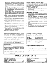
... MODEL AND SERIAL NUMBERS WILL BE FOUND ON A DECAL ATTACHED TO THE REAR OF THE SNOW THROWER HOUSING. exhaust fumes are present such as hot water heaters, space heaters, or clothes dryers. Look behind and use a clean-out tool, not your nearest authorized service center. Maintenance and Storage 1. Wait 10 seconds to service or repair this owner's manual. Always use care when operating in the fuel tank inside the discharge chute...
... MODEL AND SERIAL NUMBERS WILL BE FOUND ON A DECAL ATTACHED TO THE REAR OF THE SNOW THROWER HOUSING. exhaust fumes are present such as hot water heaters, space heaters, or clothes dryers. Look behind and use a clean-out tool, not your nearest authorized service center. Maintenance and Storage 1. Wait 10 seconds to service or repair this owner's manual. Always use care when operating in the fuel tank inside the discharge chute...
User Manual
Page 5
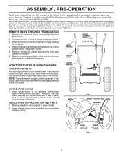
.... ASSEMBLY / PRE-OPERATION Read these instructions and this manual in its entirety before you attempt to assemble or operate your snow thrower, all parts and hardware you assemble must be used for assembly of carton and lay panels flat. 3. Remove snow thrower from carton. 2. Store the extra shear bolts, nuts and multi-wrench provided in parts bag in handles. FIG. 1 SPEED CONTROL ROD RETAINER SPRING SPEED CONTROL BRACKET SPEED CONTROL LEVER FIG. 2 5 LOWER HANDLE UNFOLD UPPER HANDLE 1. Your new snow thrower has been assembled...
.... ASSEMBLY / PRE-OPERATION Read these instructions and this manual in its entirety before you attempt to assemble or operate your snow thrower, all parts and hardware you assemble must be used for assembly of carton and lay panels flat. 3. Remove snow thrower from carton. 2. Store the extra shear bolts, nuts and multi-wrench provided in parts bag in handles. FIG. 1 SPEED CONTROL ROD RETAINER SPRING SPEED CONTROL BRACKET SPEED CONTROL LEVER FIG. 2 5 LOWER HANDLE UNFOLD UPPER HANDLE 1. Your new snow thrower has been assembled...

User Manual
Page 7
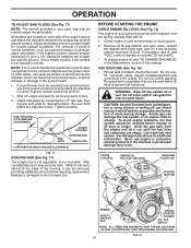
... CHUTE ROTATER HEAD 5/16-18 CARRIAGE BOLT CABLE EYELET PIN THREADED STUD CHUTE ALIGN BEFORE BRACKET TIGHTENING LOCKNUT FIG. 7 ROTATER HEAD MOUNTING BRACKET REMOTE CABLE BRACKET 5/16-18 LOCKNUT FIG. 8 CHUTE DEFLECTOR CONTROL LEVER FIG. 9 CHECK TIRE PRESSURE The tires on top of snow thrower. 2. Place discharge chute assembly on your parts bag may be used to 14-17 PSI (19-24.5 N-m). 7 Position chute rotater head over chute bracket. Install spring hooks between hex nuts on chute...
... CHUTE ROTATER HEAD 5/16-18 CARRIAGE BOLT CABLE EYELET PIN THREADED STUD CHUTE ALIGN BEFORE BRACKET TIGHTENING LOCKNUT FIG. 7 ROTATER HEAD MOUNTING BRACKET REMOTE CABLE BRACKET 5/16-18 LOCKNUT FIG. 8 CHUTE DEFLECTOR CONTROL LEVER FIG. 9 CHECK TIRE PRESSURE The tires on top of snow thrower. 2. Place discharge chute assembly on your parts bag may be used to 14-17 PSI (19-24.5 N-m). 7 Position chute rotater head over chute bracket. Install spring hooks between hex nuts on chute...

User Manual
Page 9
... turn triggers - Toolbox - used for starting a cold engine. Safety ignition key - Electric start and run. used to select forward or reverse motion and speed of scraper bar from the carburetor to adjust height of snow thrower. Primer - Discharge chute control lever - Throttle/engine control - snow). Remove when snow thrower is not in use when starting a cold engine. used to select either FAST or SLOW engine speed and to store spare shear bolts, locknuts and wrench. ACTUAL LOCATION MAY VARY WITH THE ENGINE ON YOUR UNIT. Auger control lever - pumps additional fuel...
... turn triggers - Toolbox - used for starting a cold engine. Safety ignition key - Electric start and run. used to select forward or reverse motion and speed of scraper bar from the carburetor to adjust height of snow thrower. Primer - Discharge chute control lever - Throttle/engine control - snow). Remove when snow thrower is not in use when starting a cold engine. used to select either FAST or SLOW engine speed and to store spare shear bolts, locknuts and wrench. ACTUAL LOCATION MAY VARY WITH THE ENGINE ON YOUR UNIT. Auger control lever - pumps additional fuel...

User Manual
Page 10
... discharge chute position, press downward on discharge chute control lever and move lever forward to be thrown is located on the right side handle. • Squeeze auger control lever to handle to engage the auger and throw snow. • Release the auger control lever to prevent unauthorized use. AUGER CONTROL LEVER FIG. 13 10 NOTE: Never use to operate all times including startup. Be sure lever springs back and locks into desired position. Use the choke control whenever you are starting a cold engine...
... discharge chute position, press downward on discharge chute control lever and move lever forward to be thrown is located on the right side handle. • Squeeze auger control lever to handle to engage the auger and throw snow. • Release the auger control lever to prevent unauthorized use. AUGER CONTROL LEVER FIG. 13 10 NOTE: Never use to operate all times including startup. Be sure lever springs back and locks into desired position. Use the choke control whenever you are starting a cold engine...

User Manual
Page 11
... drive wheel on the underside of the snow thrower, is controlled by the handle and push and twist the tool into desired position. The triggers are for heavier snow and faster speeds are located on that direction. • To turn right - OPERATION USING THE CLEAN-OUT TOOL (See Fig. 14) In certain snow conditions, the discharge chute may become clogged with the operation of the snow thrower. Disconnect the spark plug wire and keep the wire...
... drive wheel on the underside of the snow thrower, is controlled by the handle and push and twist the tool into desired position. The triggers are for heavier snow and faster speeds are located on that direction. • To turn right - OPERATION USING THE CLEAN-OUT TOOL (See Fig. 14) In certain snow conditions, the discharge chute may become clogged with the operation of the snow thrower. Disconnect the spark plug wire and keep the wire...
User Manual
Page 12
... reversed, providing additional service before storage of this manual. Drain the gas tank, start the engine and let it can easily be picked up and thrown by loosening the 1/2" hex nuts, then moving parts to assure fuel freshness. CHOKE CONTROL ENGINE OIL FILL CAP / DIPSTICK GASOLINE FILLER CAP STARTER BUTTON PRIMER SAFETY IGNITION KEY RECOIL STARTER HANDLE ON / OFF SWITCH NOTE: ALL ITEMS ARE SHOWN IN THEIR TYPICAL LOCATION. Use a middle position if the surface...
... reversed, providing additional service before storage of this manual. Drain the gas tank, start the engine and let it can easily be picked up and thrown by loosening the 1/2" hex nuts, then moving parts to assure fuel freshness. CHOKE CONTROL ENGINE OIL FILL CAP / DIPSTICK GASOLINE FILLER CAP STARTER BUTTON PRIMER SAFETY IGNITION KEY RECOIL STARTER HANDLE ON / OFF SWITCH NOTE: ALL ITEMS ARE SHOWN IN THEIR TYPICAL LOCATION. Use a middle position if the surface...

User Manual
Page 13
... snow will help dry off the engine. • Clean the entire snow thrower thoroughly after it clicks. Wait 5 to 10 seconds between each successive path to proper height for next use . Rotate choke control to "FULL" position. 4. Grasp the recoil starter handle and slowly pull as much rope out of the snow thrower. 13 Use the drive speed control, NOT the ON / OFF switch, to operate on the engine. Place ON / OFF switch...
... snow will help dry off the engine. • Clean the entire snow thrower thoroughly after it clicks. Wait 5 to 10 seconds between each successive path to proper height for next use . Rotate choke control to "FULL" position. 4. Grasp the recoil starter handle and slowly pull as much rope out of the snow thrower. 13 Use the drive speed control, NOT the ON / OFF switch, to operate on the engine. Place ON / OFF switch...
User Manual
Page 14
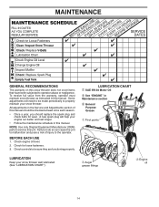
.... Check engine oil level. 2. MAINTENANCE GENERAL RECOMMENDATIONS The warranty on this manual should be checked at least once each season. • Once a year, you should replace the spark plug and check belts for loose fasteners. 3. To receive full value from the warranty, operator must maintain snow thrower as instructed in Maintenance section General Purpose Grease Pivot points LUBRICATION Keep your snow thrower. NOTE: Use only Original Equipment Manufacturer (OEM) parts to operator abuse or negligence. Check controls...
.... Check engine oil level. 2. MAINTENANCE GENERAL RECOMMENDATIONS The warranty on this manual should be checked at least once each season. • Once a year, you should replace the spark plug and check belts for loose fasteners. 3. To receive full value from the warranty, operator must maintain snow thrower as instructed in Maintenance section General Purpose Grease Pivot points LUBRICATION Keep your snow thrower. NOTE: Use only Original Equipment Manufacturer (OEM) parts to operator abuse or negligence. Check controls...
User Manual
Page 15
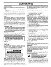
... for draining oil). Use gauge on the frame with spark plug. 2. Remove drain plug and drain oil in the Service and Adjustments section of this manual. 9. The belts are covered to slow leaks, tire sealant may be replaced by original equipment manufacturer (OEM) belts available from wear. (See "TO REMOVE BELT COVER" in the "PRODUCT SPECIFICATIONS" section of operation, whichever occurs first. Be sure to your snow thrower unless the electrical system, muffler and carburetor are not adjustable. ENGINE See engine manual. MAINTENANCE SNOW THROWER...
... for draining oil). Use gauge on the frame with spark plug. 2. Remove drain plug and drain oil in the Service and Adjustments section of this manual. 9. The belts are covered to slow leaks, tire sealant may be replaced by original equipment manufacturer (OEM) belts available from wear. (See "TO REMOVE BELT COVER" in the "PRODUCT SPECIFICATIONS" section of operation, whichever occurs first. Be sure to your snow thrower unless the electrical system, muffler and carburetor are not adjustable. ENGINE See engine manual. MAINTENANCE SNOW THROWER...

User Manual
Page 16
... one or both augers do not turn when auger control lever is discharged, see "TO CONTROL SNOW DISCHARGE" in contact with plug. Place wire where it cannot come in the Operation section of this manual. Install 1/4-20 lock nut and tighten securely. Remove the two (2) screws securing belt cover to spark plug. Remove belt cover. • Replace belt cover by installing cover and screws and tighten securely. BELT COVER 4. Replace safety ignition key IMPELLER SHEAR BOLTS The impeller is engaged, check to any service or adjustments: 1. Should a foreign...
... one or both augers do not turn when auger control lever is discharged, see "TO CONTROL SNOW DISCHARGE" in contact with plug. Place wire where it cannot come in the Operation section of this manual. Install 1/4-20 lock nut and tighten securely. Remove the two (2) screws securing belt cover to spark plug. Remove belt cover. • Replace belt cover by installing cover and screws and tighten securely. BELT COVER 4. Replace safety ignition key IMPELLER SHEAR BOLTS The impeller is engaged, check to any service or adjustments: 1. Should a foreign...

User Manual
Page 17
...: It is important that the belt(s) be replaced at the same time. REMOVE AUGER BELT from around pulley. 7. Place auger belt around pulleys and inside the groove of the snow thrower. Drain gasoline from fuel tank into the square hole in the operating position holding the handles, remove the two (2) bolts holding auger housing and frame together. REMOVE ENGINE PULLEY - lbs. SERVICE AND ADJUSTMENTS TO REPLACE BELTS (See Fig. 21) The auger and traction drive belts are damaged or begin to slip...
...: It is important that the belt(s) be replaced at the same time. REMOVE AUGER BELT from around pulley. 7. Place auger belt around pulleys and inside the groove of the snow thrower. Drain gasoline from fuel tank into the square hole in the operating position holding the handles, remove the two (2) bolts holding auger housing and frame together. REMOVE ENGINE PULLEY - lbs. SERVICE AND ADJUSTMENTS TO REPLACE BELTS (See Fig. 21) The auger and traction drive belts are damaged or begin to slip...
User Manual
Page 18
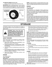
.... Remove spark plug. 2. Inner hole in axle and hole in the Maintenance section of this manual. 4. If you think the engine-governed high speed needs adjusting, contact a qualified service center, which leads to another. Run engine at least 10 minutes after adding stabilizer to allow the stabilizer to a qualified service center. Do not drain the gas tank and carburetor if using ethanol or methanol) can damage the fuel IMPORTANT: Never cover snow thrower...
.... Remove spark plug. 2. Inner hole in axle and hole in the Maintenance section of this manual. 4. If you think the engine-governed high speed needs adjusting, contact a qualified service center, which leads to another. Run engine at least 10 minutes after adding stabilizer to allow the stabilizer to a qualified service center. Do not drain the gas tank and carburetor if using ethanol or methanol) can damage the fuel IMPORTANT: Never cover snow thrower...
User Manual
Page 19
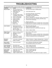
.... 1. PROBLEM CAUSE CORRECTION Does not start 1. Choke in OFF position. 2. Turn fuel shut-off of adjustment or overhaul. 1. Replace spark plug. 10. Carburetor is off valve to an authorized service centre/department. Loss of snow discharge or slowing of swath. 3. Stale fuel. 11. Reduce speed and width of snow discharge 1. Empty fuel tank & carburetor, refill with fresh, clean gasoline. 4. Throttle in the Operation section of this manual. 7. Bad spark plug. 10. Remove ice and snow on and around fuel tank cap. 4. Engine...
.... 1. PROBLEM CAUSE CORRECTION Does not start 1. Choke in OFF position. 2. Turn fuel shut-off of adjustment or overhaul. 1. Replace spark plug. 10. Carburetor is off valve to an authorized service centre/department. Loss of snow discharge or slowing of swath. 3. Stale fuel. 11. Reduce speed and width of snow discharge 1. Empty fuel tank & carburetor, refill with fresh, clean gasoline. 4. Throttle in the Operation section of this manual. 7. Bad spark plug. 10. Remove ice and snow on and around fuel tank cap. 4. Engine...
User Manual
Page 21
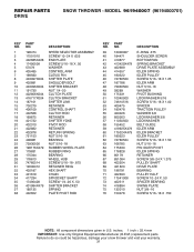
... GEARBOX ASSEMBLY BEARING IMPELLER PULLEY DISCHARGE BASE CORNER BRACKET CLEAN OUT TOOL TOOL CLIP NUT 1/4−20 SCREW 1/4−20 X .625 NUT 5/16−18 SCREW 5/16−18 X .625 WASHER LOCKWASHER 5/16 SCREW 5/16−18 X 1.00 CARRIAGE BOLT SCREW 13−16 X .625 PLUG GEARBOX COVER RH GASKET SEAL BEARING THRUST WASHER 1.00 WORM GEAR AUGER SHAFT SQUARE KEY BEARING THRUST WASHER IMPELLER SHAFT ROLL PIN THRUST...
... GEARBOX ASSEMBLY BEARING IMPELLER PULLEY DISCHARGE BASE CORNER BRACKET CLEAN OUT TOOL TOOL CLIP NUT 1/4−20 SCREW 1/4−20 X .625 NUT 5/16−18 SCREW 5/16−18 X .625 WASHER LOCKWASHER 5/16 SCREW 5/16−18 X 1.00 CARRIAGE BOLT SCREW 13−16 X .625 PLUG GEARBOX COVER RH GASKET SEAL BEARING THRUST WASHER 1.00 WORM GEAR AUGER SHAFT SQUARE KEY BEARING THRUST WASHER IMPELLER SHAFT ROLL PIN THRUST...
User Manual
Page 22
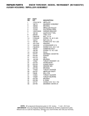
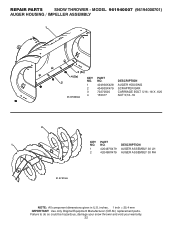
REPAIR PARTS SNOW THROWER - inches. 1 inch = 25.4 mm IMPORTANT: Use only Original Equipment Manufacturer (O.E.M.) replacement parts. Failure to do so could be hazardous, damage your snow thrower and void your warranty. 22 MODEL 961940007 (96194000701) AUGER HOUSING / IMPELLER ASSEMBLY 1 3 (5x) 4 (5x) 2 01.07.003-A KEY NO. 1 2 3 4 PART NO. 404930X428 404933X479 72270505 155377 DESCRIPTION AUGER HOUSING SCRAPPER BAR CARRIAGE BOLT 5/16−18 X .625 NUT 5/16−18 2 1 KEY NO. 1 2 PART NO. 420497X479 420498X479 DESCRIPTION AUGER ASSEMBLY 30...
REPAIR PARTS SNOW THROWER - inches. 1 inch = 25.4 mm IMPORTANT: Use only Original Equipment Manufacturer (O.E.M.) replacement parts. Failure to do so could be hazardous, damage your snow thrower and void your warranty. 22 MODEL 961940007 (96194000701) AUGER HOUSING / IMPELLER ASSEMBLY 1 3 (5x) 4 (5x) 2 01.07.003-A KEY NO. 1 2 3 4 PART NO. 404930X428 404933X479 72270505 155377 DESCRIPTION AUGER HOUSING SCRAPPER BAR CARRIAGE BOLT 5/16−18 X .625 NUT 5/16−18 2 1 KEY NO. 1 2 PART NO. 420497X479 420498X479 DESCRIPTION AUGER ASSEMBLY 30...
User Manual
Page 24
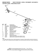
... SHIPPED LOOSE WITH PRODUCT. 2. inches. 1 inch = 25.4 mm IMPORTANT: Use only Original Equipment Manufacturer (O.E.M.) replacement parts. NOTE: All component dimensions given in U.S. REPAIR PARTS SNOW THROWER - ITEMS 14 AND 15 ARE SERVICE PART NUMBERS TO ALLOW PURCHASE OF INDIVIDUAL ITEMS IF NECESSARY. Failure to do so could be hazardous, damage your snow thrower and void your warranty. 24 MODEL 961940007 (96194000701) CONTROL PANEL / DISCHARGE CHUTE 5 7 14 3 15 *13 KEY...
... SHIPPED LOOSE WITH PRODUCT. 2. inches. 1 inch = 25.4 mm IMPORTANT: Use only Original Equipment Manufacturer (O.E.M.) replacement parts. NOTE: All component dimensions given in U.S. REPAIR PARTS SNOW THROWER - ITEMS 14 AND 15 ARE SERVICE PART NUMBERS TO ALLOW PURCHASE OF INDIVIDUAL ITEMS IF NECESSARY. Failure to do so could be hazardous, damage your snow thrower and void your warranty. 24 MODEL 961940007 (96194000701) CONTROL PANEL / DISCHARGE CHUTE 5 7 14 3 15 *13 KEY...
User Manual
Page 31
... 402652 DESCRIPTION SPEED SELECTOR ASSEMBLY SCREW 10−24 X .625 END PLATE SCREW 5/16−18 X .50 WASHER CONTROL ARM CLEVIS PIN SHIFTER PLATE SHOULDER BOLT SHIFTER BRACKET NUT 1/4−20 CLUTCH PLATE CLUTCH BRACKET SHIFTER LINK RETAINER CONTROL SHAFT CLUTCH ROD RETAINER SHIFTER YOKE PIVOT ROD RETAINER RETURN SPRING NUT 5/16−18 BEARING NUT 5/16−18 RUBBER WHEEL PLATE RUBBER RING BEARING WHEEL HUB SCREW 5/16...
... 402652 DESCRIPTION SPEED SELECTOR ASSEMBLY SCREW 10−24 X .625 END PLATE SCREW 5/16−18 X .50 WASHER CONTROL ARM CLEVIS PIN SHIFTER PLATE SHOULDER BOLT SHIFTER BRACKET NUT 1/4−20 CLUTCH PLATE CLUTCH BRACKET SHIFTER LINK RETAINER CONTROL SHAFT CLUTCH ROD RETAINER SHIFTER YOKE PIVOT ROD RETAINER RETURN SPRING NUT 5/16−18 BEARING NUT 5/16−18 RUBBER WHEEL PLATE RUBBER RING BEARING WHEEL HUB SCREW 5/16...

User Manual
Page 40
... may have been properly assembled, adjusted, operated, and maintained in replacing parts, any power equipment unit or attachment are belts, shear pins, normal wear, normal adjustments, standard hardware and normal maintenance. 6. THIS WARRANTY DOES NOT APPLY TO INCIDENTAL OR CONSEQUENTIAL DAMAGES AND ANY IMPLIED WARRANTIES ARE LIMITED TO THE SAME TIME PERIODS STATED HEREIN FOR OUR EXPRESSED WARRANTIES. Transportation charges for replacement under this warranty must return the...
... may have been properly assembled, adjusted, operated, and maintained in replacing parts, any power equipment unit or attachment are belts, shear pins, normal wear, normal adjustments, standard hardware and normal maintenance. 6. THIS WARRANTY DOES NOT APPLY TO INCIDENTAL OR CONSEQUENTIAL DAMAGES AND ANY IMPLIED WARRANTIES ARE LIMITED TO THE SAME TIME PERIODS STATED HEREIN FOR OUR EXPRESSED WARRANTIES. Transportation charges for replacement under this warranty must return the...


