
User Manual
Page 2
... such structures or buildings. Never attempt to prevent accidental starting when setting up spilled fuel. (h) If fuel is running engine or hot engine. restarting and operating the snow thrower. If this symbol to a running (except when specifically recommended by the manufacturer for all times. (a) Use an approved fuel container. 2. Stop the engine (motor) whenever you leave the operating position, before operating this unit. BECOME ALERT!!! Do not put hands or...
... such structures or buildings. Never attempt to prevent accidental starting when setting up spilled fuel. (h) If fuel is running engine or hot engine. restarting and operating the snow thrower. If this symbol to a running (except when specifically recommended by the manufacturer for all times. (a) Use an approved fuel container. 2. Stop the engine (motor) whenever you leave the operating position, before operating this unit. BECOME ALERT!!! Do not put hands or...
User Manual
Page 3
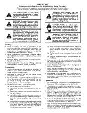
... service or repair this manual. Disconnect the spark plug wire and keep a firm hold on slippery surfaces. Disengage power to be sure the equipment is the most common cause of injury associated with the rotating impeller inside a building where ignition sources are dangerous. 8. Never operate the snow thrower without proper guards, and other bolts at high transport speeds on the handles. Never store the machine with fuel...
... service or repair this manual. Disconnect the spark plug wire and keep a firm hold on slippery surfaces. Disengage power to be sure the equipment is the most common cause of injury associated with the rotating impeller inside a building where ignition sources are dangerous. 8. Never operate the snow thrower without proper guards, and other bolts at high transport speeds on the handles. Never store the machine with fuel...
User Manual
Page 4
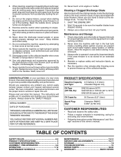
...from carton and check carton thoroughly for ship- 3. PARTS PACKED SEPARATELY IN CARTON (1) AUGER CONTROL ROD (1) DISCHARGE CHUTE (1) POWER CORD (198563) ROTATOR HEAD MOUNTING (1) MULTIWRENCH (180684) (3) RETAINER SPRINGS (169675) (2) FLAT WASHERS (2) CARRIAGE BOLTS 3/8-16 x 2.25 (1) WASHER 3/8 (19131316) (1) LOCKNUT 3/8 (73800600) SAFTEY IGNITION KEY(S) (422663) EXTRA SHEAR BOLTS AND NUTS (2) HANDLE KNOBS (2) SHEAR BOLTS 1/4-20 x 1-3/4 (192090) (2) LOCKNUTS 1/4-20 (73800400) ASSEMBLY / PRE-OPERATION Read these instructions and this manual in speed control rod to ensure...
...from carton and check carton thoroughly for ship- 3. PARTS PACKED SEPARATELY IN CARTON (1) AUGER CONTROL ROD (1) DISCHARGE CHUTE (1) POWER CORD (198563) ROTATOR HEAD MOUNTING (1) MULTIWRENCH (180684) (3) RETAINER SPRINGS (169675) (2) FLAT WASHERS (2) CARRIAGE BOLTS 3/8-16 x 2.25 (1) WASHER 3/8 (19131316) (1) LOCKNUT 3/8 (73800600) SAFTEY IGNITION KEY(S) (422663) EXTRA SHEAR BOLTS AND NUTS (2) HANDLE KNOBS (2) SHEAR BOLTS 1/4-20 x 1-3/4 (192090) (2) LOCKNUTS 1/4-20 (73800400) ASSEMBLY / PRE-OPERATION Read these instructions and this manual in speed control rod to ensure...
User Manual
Page 5
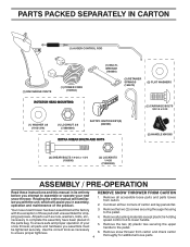
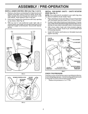
Additional carriage bolts, washers and handle knobs are in the toolbox. INSTALL TRACTION DRIVE CONTROL ROD (See Figs. 3 and 4) The traction drive control rod is located on top of the chute rotator head to snow thrower and making adjustments to lower handle. 2. Secure with retainer spring. UPPER HANDLE SPEED CONTROL ROD PLASTIC TIE HANDLE KNOB INSTALL SPEED CONTROL ROD (See Figs. 1 and 2) 1. NOTE: The multi-wrench may be used for assembly of the belt cover. UNFOLD UPPER HANDLE 1. Insert rod...
Additional carriage bolts, washers and handle knobs are in the toolbox. INSTALL TRACTION DRIVE CONTROL ROD (See Figs. 3 and 4) The traction drive control rod is located on top of the chute rotator head to snow thrower and making adjustments to lower handle. 2. Secure with retainer spring. UPPER HANDLE SPEED CONTROL ROD PLASTIC TIE HANDLE KNOB INSTALL SPEED CONTROL ROD (See Figs. 1 and 2) 1. NOTE: The multi-wrench may be used for assembly of the belt cover. UNFOLD UPPER HANDLE 1. Insert rod...
User Manual
Page 6
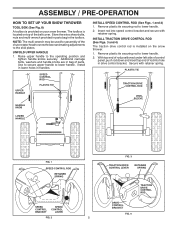
.... 2. Position chute rotator head over chute bracket. CHUTE ROTATOR HEAD 3/8 LOCKNUT 3/8 WASHER LOOP OPENING UP FIG. 5 AUGER CONTROL ROD AUGER CONTROL RETAINER LEVER SPRING PIN THREADED STUD CHUTE BRACKET ALIGN BEFORE TIGHTENING LOCKNUT ROTATOR HEAD MOUNTING BRACKET FIG. 7 CHECK TIRE PRESSURE The tires on pin and threaded stud of chute base with holes in chute bracket. 3. With chute rotator head and chute bracket aligned, position chute rotator head on your parts bag may be used to install the chute rotator head...
.... 2. Position chute rotator head over chute bracket. CHUTE ROTATOR HEAD 3/8 LOCKNUT 3/8 WASHER LOOP OPENING UP FIG. 5 AUGER CONTROL ROD AUGER CONTROL RETAINER LEVER SPRING PIN THREADED STUD CHUTE BRACKET ALIGN BEFORE TIGHTENING LOCKNUT ROTATOR HEAD MOUNTING BRACKET FIG. 7 CHECK TIRE PRESSURE The tires on pin and threaded stud of chute base with holes in chute bracket. 3. With chute rotator head and chute bracket aligned, position chute rotator head on your parts bag may be used to install the chute rotator head...

User Manual
Page 8
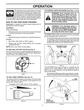
... snow thrower is thrown. Electric start and run. used to start button - Primer - Discharge chute control knob - Choke control - MUFFLER GASOLINE FILLER CAP CHOKE CONTROL SAFETY IGNITION KEY ON / OFF SWITCH PRIMER FUEL SHUT-OFF VALVE RECOIL (AUXILIARY) STARTER HANDLE NOTE: ITEMS ABOVE ARE SHOWN IN THEIR TYPICAL LOCATION ON THE ENGINE. OPERATION ELECTRIC START BUTTON POWER CORD PLUG AUGER CONTROL LEVER DEFLECTOR REMOTE CONTROL LEVER DRIVE SPEED CONTROL LEVER CHUTE DEFLECTOR TRACTION DRIVE CONTROL LEVER LIGHT DISCHARGE CHUTE DISCHARGE CHUTE CONTROL KNOB CLEAN-OUT TOOL HANDLE...
... snow thrower is thrown. Electric start and run. used to start button - Primer - Discharge chute control knob - Choke control - MUFFLER GASOLINE FILLER CAP CHOKE CONTROL SAFETY IGNITION KEY ON / OFF SWITCH PRIMER FUEL SHUT-OFF VALVE RECOIL (AUXILIARY) STARTER HANDLE NOTE: ITEMS ABOVE ARE SHOWN IN THEIR TYPICAL LOCATION ON THE ENGINE. OPERATION ELECTRIC START BUTTON POWER CORD PLUG AUGER CONTROL LEVER DEFLECTOR REMOTE CONTROL LEVER DRIVE SPEED CONTROL LEVER CHUTE DEFLECTOR TRACTION DRIVE CONTROL LEVER LIGHT DISCHARGE CHUTE DISCHARGE CHUTE CONTROL KNOB CLEAN-OUT TOOL HANDLE...
User Manual
Page 9
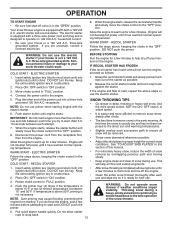
... choke control is controlled by the discharge chute control lever. • To change the deflector position, loosen knob, move lever left or right until chute is in which snow is controlled by the position of any adjustments or repairs. Set the deflector low to start a warm engine. • To engage choke, rotate lever to throw snow farther. • To change the discharge chute position, press downward on the engine. HOW TO USE YOUR SNOW THROWER Know how to operate all times...
... choke control is controlled by the discharge chute control lever. • To change the deflector position, loosen knob, move lever left or right until chute is in which snow is controlled by the position of any adjustments or repairs. Set the deflector low to start a warm engine. • To engage choke, rotate lever to throw snow farther. • To change the discharge chute position, press downward on the engine. HOW TO USE YOUR SNOW THROWER Know how to operate all times...
User Manual
Page 10
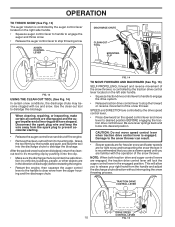
.... • Make sure the discharge chute is engaged. Damage to prevent accidental starting. • Release the auger control lever and shut off the engine. • Remove the clean-out tool from the spark plug to the snow thrower can result. • Slower speeds are for heavier snow and faster speeds are controlled by the drive speed control lever. • Press downward on the speed control lever and move speed control lever when traction drive control lever is pointed in a safe...
.... • Make sure the discharge chute is engaged. Damage to prevent accidental starting. • Release the auger control lever and shut off the engine. • Remove the clean-out tool from the spark plug to the snow thrower can result. • Slower speeds are for heavier snow and faster speeds are controlled by the drive speed control lever. • Press downward on the speed control lever and move speed control lever when traction drive control lever is pointed in a safe...
User Manual
Page 11
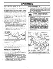
.... ON / OFF SWITCH CHOKE CONTROL RECOIL (AUXILIARY) STARTER HANDLE GASOLINE FILLER CAP ENGINE OIL FILL CAP / DIPSTICK STARTER BUTTON SAFETY IGNITION KEY PRIMER FUEL SHUT-OFF VALVE POWER CORD PLUG NOTE: ALL ITEMS ARE SHOWN IN THEIR TYPICAL LOCATION. OPERATION TO ADJUST SKID PLATES (See Fig. 16) NOTE: The wrench provided in your snow thrower has been shipped from the factory already filled with a minimum of 87 octane. After considerable use gasoline near...
.... ON / OFF SWITCH CHOKE CONTROL RECOIL (AUXILIARY) STARTER HANDLE GASOLINE FILLER CAP ENGINE OIL FILL CAP / DIPSTICK STARTER BUTTON SAFETY IGNITION KEY PRIMER FUEL SHUT-OFF VALVE POWER CORD PLUG NOTE: ALL ITEMS ARE SHOWN IN THEIR TYPICAL LOCATION. OPERATION TO ADJUST SKID PLATES (See Fig. 16) NOTE: The wrench provided in your snow thrower has been shipped from the factory already filled with a minimum of 87 octane. After considerable use gasoline near...
User Manual
Page 12
... next use and wipe dry so it clicks. Place ON / OFF switch in this section of the snow thrower. 5. If temperature is designed to "FULL" position. 4. Pull recoil starter handle quickly. Insert safety ignition key (tied to the "OFF" position. 8. Disconnect the power cord from the receptacle first, then from starting engine with both a 120 Volt A.C. COLD START - Rotate choke control to the safe operation of this time the snow...
... next use and wipe dry so it clicks. Place ON / OFF switch in this section of the snow thrower. 5. If temperature is designed to "FULL" position. 4. Pull recoil starter handle quickly. Insert safety ignition key (tied to the "OFF" position. 8. Disconnect the power cord from the receptacle first, then from starting engine with both a 120 Volt A.C. COLD START - Rotate choke control to the safe operation of this time the snow...
User Manual
Page 13
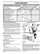
... air pressure in this manual. Using other slow leaks, tire sealant may be checked at least once each season. • Once a year, you should be purchased from your nearest dealer. Check engine oil level. 2. Check for deterioration and wear after every 50 hours maintenance. Check controls to be made periodically to properly maintain your snow thrower. Tire sealant also prevents tire dry rot and the snow thrower. A new spark plug...
... air pressure in this manual. Using other slow leaks, tire sealant may be checked at least once each season. • Once a year, you should be purchased from your nearest dealer. Check engine oil level. 2. Check for deterioration and wear after every 50 hours maintenance. Check controls to be made periodically to properly maintain your snow thrower. Tire sealant also prevents tire dry rot and the snow thrower. A new spark plug...
User Manual
Page 14
... dipstick cap is required, use only Ronex ED #1 grease. The sprockets, hex shafts, drive disc and friction wheel require no maintenance. Wipe off any oil trapped inside the snow thrower. Do not overfill. Clean the outside of this manual). 1. CAUTION: Any lubricating of this manual). 7. Check the crankcase oil level before next oil change. NOTE: The left side wheel may be removed from snow thrower and engine. 6. Remove safety ignition key and disconnect spark plug wire from spark plug. Be...
... dipstick cap is required, use only Ronex ED #1 grease. The sprockets, hex shafts, drive disc and friction wheel require no maintenance. Wipe off any oil trapped inside the snow thrower. Do not overfill. Clean the outside of this manual). 1. CAUTION: Any lubricating of this manual). 7. Check the crankcase oil level before next oil change. NOTE: The left side wheel may be removed from snow thrower and engine. 6. Remove safety ignition key and disconnect spark plug wire from spark plug. Be...
User Manual
Page 15
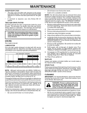
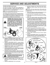
... operate your snow thrower. 4. To replace the shear bolts: 1. Remove safety ignition key and disconnect spark plug wire from spark plug. Use only original equipment capscrew/shear bolts as supplied with hole in auger hub with your snow thrower. 4. Wait for all controls and move throttle control to the auger shaft with two (2) capscrew/shear bolts and hex nuts. Be sure the on/off switch is engaged, check to the top of this manual. CHUTE DEFLECTOR The chute deflector, attached to see "TO CONTROL SNOW...
... operate your snow thrower. 4. To replace the shear bolts: 1. Remove safety ignition key and disconnect spark plug wire from spark plug. Use only original equipment capscrew/shear bolts as supplied with hole in auger hub with your snow thrower. 4. Wait for all controls and move throttle control to the auger shaft with two (2) capscrew/shear bolts and hex nuts. Be sure the on/off switch is engaged, check to the top of this manual. CHUTE DEFLECTOR The chute deflector, attached to see "TO CONTROL SNOW...
User Manual
Page 16
... operating position and hold the snow thrower handles. INSTALL ENGINE PULLEY - See "INSTALL DISCHARGE CHUTE / CHUTE ROTATER HEAD" in this section of this manual. 4. REMOVE BELT COVER - If the belts are not adjustable. If auger belt has become dislodged from fire or flame. Install clutch rod in groove of pulley. 13. Drain gasoline from fuel tank into the square hole in pulley groove and slide pulley on your snow thrower are of auger pulley only. 12. REMOVE AUGER BELT from around pulley. 16 FIG. 20 FRAME ASSEMBLY AUGER HOUSING HANDLES...
... operating position and hold the snow thrower handles. INSTALL ENGINE PULLEY - See "INSTALL DISCHARGE CHUTE / CHUTE ROTATER HEAD" in this section of this manual. 4. REMOVE BELT COVER - If the belts are not adjustable. If auger belt has become dislodged from fire or flame. Install clutch rod in groove of pulley. 13. Drain gasoline from fuel tank into the square hole in pulley groove and slide pulley on your snow thrower are of auger pulley only. 12. REMOVE AUGER BELT from around pulley. 16 FIG. 20 FRAME ASSEMBLY AUGER HOUSING HANDLES...
User Manual
Page 17
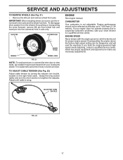
... (2,134 meters). If your engine does not operate properly due to use the innermost hole in axle only. If you think the engine-governed high speed needs adjusting, contact a qualified service center, which is snug. Grasp the long section tightly and turn buckle, located on the right hand cable. Adjust until cable is factory set for pushing or transporting the snow thrower), remove klik pin from axle. Tire sealant...
... (2,134 meters). If your engine does not operate properly due to use the innermost hole in axle only. If you think the engine-governed high speed needs adjusting, contact a qualified service center, which is snug. Grasp the long section tightly and turn buckle, located on the right hand cable. Adjust until cable is factory set for pushing or transporting the snow thrower), remove klik pin from axle. Tire sealant...
User Manual
Page 18
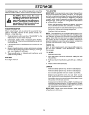
... or if the unit will cause your snow thrower to rust. ENGINE OIL Drain oil (with engine warm) and replace with gasoline in the tank inside a building where fumes may occur. • Use fresh fuel next season. Pour one season to another. • Replace your gasoline can if your snow thrower with new spark plug. Pull recoil starter handle slowly a few times to reach the carburetor. store it from one ounce (29...
... or if the unit will cause your snow thrower to rust. ENGINE OIL Drain oil (with engine warm) and replace with gasoline in the tank inside a building where fumes may occur. • Use fresh fuel next season. Pour one season to another. • Replace your gasoline can if your snow thrower with new spark plug. Pull recoil starter handle slowly a few times to reach the carburetor. store it from one ounce (29...
User Manual
Page 19
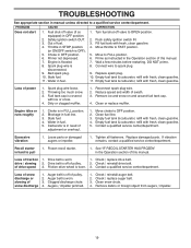
...fuel line. 3. Contact a qualified service center/department. Replace damaged parts. See "IF RECOIL STARTER HAS FROZEN" in the Operation section of adjustment or overhaul. 1. Remove debris or foreign object from augers / impeller. 19 Choke in fuel. 1. Engine is in need of this manual. 7. Bad spark plug. 10. Prime as instructed in the Operation section of pulley. 2. Spark plug wire loose. 2. Dirty or clogged muffler. 1. drive / slowing 2. Drive belt is off valve to OPEN position. 2. of fuel. 4. Safety ignition switch OUT. 3. Stale fuel...
...fuel line. 3. Contact a qualified service center/department. Replace damaged parts. See "IF RECOIL STARTER HAS FROZEN" in the Operation section of adjustment or overhaul. 1. Remove debris or foreign object from augers / impeller. 19 Choke in fuel. 1. Engine is in need of this manual. 7. Bad spark plug. 10. Prime as instructed in the Operation section of pulley. 2. Spark plug wire loose. 2. Dirty or clogged muffler. 1. drive / slowing 2. Drive belt is off valve to OPEN position. 2. of fuel. 4. Safety ignition switch OUT. 3. Stale fuel...
User Manual
Page 22
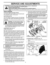
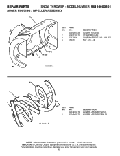
REPAIR PARTS SNOW THROWER - MODEL NUMBER 96194000801 AUGER HOUSING / IMPELLER ASSEMBLY 1 KEY NO. 1 2 3 4 PART NO. 404928X428 404931X479 72270505 155377 DESCRIPTION AUGER HOUSING SCRAPPER BAR CARRIAGE BOLT 5/16−18 X .625 NUT 5/16−18 3 (5x) 4 (5x) 2 01.07.001-A 2 1 01.07.017-A KEY NO. 1 2 PART NO. 420493X479 420494X479 DESCRIPTION AUGER ASSEMBLY LH 24 AUGER ASSEMBLY RH 24 NOTE: All component dimensions given in U.S. inches. 1 inch = 25.4 mm IMPORTANT: Use only Original Equipment Manufacturer (O.E.M.) replacement parts. Failure to...
REPAIR PARTS SNOW THROWER - MODEL NUMBER 96194000801 AUGER HOUSING / IMPELLER ASSEMBLY 1 KEY NO. 1 2 3 4 PART NO. 404928X428 404931X479 72270505 155377 DESCRIPTION AUGER HOUSING SCRAPPER BAR CARRIAGE BOLT 5/16−18 X .625 NUT 5/16−18 3 (5x) 4 (5x) 2 01.07.001-A 2 1 01.07.017-A KEY NO. 1 2 PART NO. 420493X479 420494X479 DESCRIPTION AUGER ASSEMBLY LH 24 AUGER ASSEMBLY RH 24 NOTE: All component dimensions given in U.S. inches. 1 inch = 25.4 mm IMPORTANT: Use only Original Equipment Manufacturer (O.E.M.) replacement parts. Failure to...
User Manual
Page 25
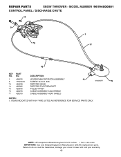
MODEL NUMBER 96194000801 CONTROL PANEL / DISCHARGE CHUTE 2 2 *3 1 *7 *6 KEY NO. 1 2 *3 *4 *5 *6 *7 PART NO. 428272 17501010 420678 405932 420675 428273 428310 DESCRIPTION LEVER/CABLE ROTATOR ASSEMBLY SCREW 10-24 X .625 ROTATOR HEAD ROTATOR PIVOT BRACKET PULLEY PIVOT CABLE ASSEMBLY ADJUSTABLE CABLE ASSEMBLY HEAT SHIELD *4 01.09.010-B *5 NOTES: 1. inches. 1 inch = 25.4 mm IMPORTANT: Use only Original Equipment Manufacturer (O.E.M.) replacement parts. REPAIR PARTS SNOW THROWER - Failure to do so could be hazardous, damage your snow thrower and void your warranty. 43 ITEMS ...
MODEL NUMBER 96194000801 CONTROL PANEL / DISCHARGE CHUTE 2 2 *3 1 *7 *6 KEY NO. 1 2 *3 *4 *5 *6 *7 PART NO. 428272 17501010 420678 405932 420675 428273 428310 DESCRIPTION LEVER/CABLE ROTATOR ASSEMBLY SCREW 10-24 X .625 ROTATOR HEAD ROTATOR PIVOT BRACKET PULLEY PIVOT CABLE ASSEMBLY ADJUSTABLE CABLE ASSEMBLY HEAT SHIELD *4 01.09.010-B *5 NOTES: 1. inches. 1 inch = 25.4 mm IMPORTANT: Use only Original Equipment Manufacturer (O.E.M.) replacement parts. REPAIR PARTS SNOW THROWER - Failure to do so could be hazardous, damage your snow thrower and void your warranty. 43 ITEMS ...
User Manual
Page 38
... product to an authorized service dealer. Should you 1/12 of the price of a new Battery for the movement of any power equipment unit or attachment are belts, blades, blade adapters, normal wear, normal adjustments, standard hardware and normal maintenance. 7. THIS WARRANTY DOES NOT APPLY TO INCIDENTAL OR CONSEQUENTIAL DAMAGES AND ANY IMPLIED WARRANTIES ARE LIMITED TO THE SAME TIME PERIODS STATED HEREIN FOR...
... product to an authorized service dealer. Should you 1/12 of the price of a new Battery for the movement of any power equipment unit or attachment are belts, blades, blade adapters, normal wear, normal adjustments, standard hardware and normal maintenance. 7. THIS WARRANTY DOES NOT APPLY TO INCIDENTAL OR CONSEQUENTIAL DAMAGES AND ANY IMPLIED WARRANTIES ARE LIMITED TO THE SAME TIME PERIODS STATED HEREIN FOR...


