
User Manual
Page 2
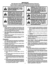
... discharge chute. Handle fuel with extreme care. it is for all times including startup. Do not use a nozzle lock-open device. (g) Replace gasoline cap securely and wipe up , transporting, adjusting or making any damage, and repair the damage before trailer bed with electric drive motors or electric starting when setting up spilled fuel. (h) If fuel is to a running (except when specifically recommended by the manufacturer for use on clothing, change clothing immediately. 5. Operation...
... discharge chute. Handle fuel with extreme care. it is for all times including startup. Do not use a nozzle lock-open device. (g) Replace gasoline cap securely and wipe up , transporting, adjusting or making any damage, and repair the damage before trailer bed with electric drive motors or electric starting when setting up spilled fuel. (h) If fuel is to a running (except when specifically recommended by the manufacturer for use on clothing, change clothing immediately. 5. Operation...

User Manual
Page 3
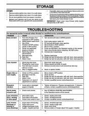
... THE SNOW THROWER HOUSING. 6. Do not run . 16. Never operate the snow thrower without proper guards, and other bolts at too fast a rate. 12. Maintain or replace safety and instruction labels, as wheel weights, counterweights, or cabs). 15. TABLE OF CONTENTS SAFETY RULES 2-3 MAINTENANCE SCHEDULE 14 PRODUCT SPECIFICATIONS 3 SERVICE AND ADJUSTMENTS 16-18 CUSTOMER RESPONSIBILITIES 3 STORAGE 18-19 ASSEMBLY / PRE-OPERATION 5-7 TROUBLESHOOTING 20 OPERATION 8-13 REPAIR PARTS 38-51 MAINTENANCE 14-15 3 WARRANTY 52...
... THE SNOW THROWER HOUSING. 6. Do not run . 16. Never operate the snow thrower without proper guards, and other bolts at too fast a rate. 12. Maintain or replace safety and instruction labels, as wheel weights, counterweights, or cabs). 15. TABLE OF CONTENTS SAFETY RULES 2-3 MAINTENANCE SCHEDULE 14 PRODUCT SPECIFICATIONS 3 SERVICE AND ADJUSTMENTS 16-18 CUSTOMER RESPONSIBILITIES 3 STORAGE 18-19 ASSEMBLY / PRE-OPERATION 5-7 TROUBLESHOOTING 20 OPERATION 8-13 REPAIR PARTS 38-51 MAINTENANCE 14-15 3 WARRANTY 52...
User Manual
Page 5
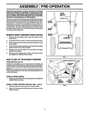
... TIE REMOVE SNOW THROWER FROM CARTON 1. Remove all four corners of the chute rotator head to snow thrower and making adjustments to the skid plates. HOW TO SET UP YOUR SNOW THROWER TOOL BOX (See Fig. 10) A toolbox is located on your new snow thrower. Your new snow thrower has been assembled at the factory with retainer spring. Remove snow thrower from carton. 2. LOWER HANDLE FIG. 1 SPEED CONTROL ROD RETAINER SPRING UNFOLD UPPER HANDLE 1. ASSEMBLY / PRE-OPERATION Read these instructions and this manual in...
... TIE REMOVE SNOW THROWER FROM CARTON 1. Remove all four corners of the chute rotator head to snow thrower and making adjustments to the skid plates. HOW TO SET UP YOUR SNOW THROWER TOOL BOX (See Fig. 10) A toolbox is located on your new snow thrower. Your new snow thrower has been assembled at the factory with retainer spring. Remove snow thrower from carton. 2. LOWER HANDLE FIG. 1 SPEED CONTROL ROD RETAINER SPRING UNFOLD UPPER HANDLE 1. ASSEMBLY / PRE-OPERATION Read these instructions and this manual in...

User Manual
Page 7
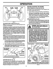
... as shown. 1/4-20 SHOULDER BOLT NYLON WASHER 1/4-20 LOCKNUT SPRING CHUTE DEFLECTOR HOOK BETWEEN HEX NUTS ON CHUTE ROTATER HEAD 5/16-18 CARRIAGE BOLT CABLE EYELET CHUTE BRACKET ALIGN BEFORE TIGHTENING LOCKNUT FIG. 7 PIN THREADED STUD ROTATOR HEAD MOUNTING BRACKET REMOTE CABLE BRACKET 5/16-18 LOCKNUT FIG. 8 CHUTE DEFLECTOR CONTROL LEVER FIG. 9 CHECK TIRE PRESSURE The tires on top of snow thrower. 2. ASSEMBLY / PRE-OPERATION INSTALL DISCHARGE CHUTE / CHUTE ROTATOR HEAD (See Fig. 7) NOTE: The...
... as shown. 1/4-20 SHOULDER BOLT NYLON WASHER 1/4-20 LOCKNUT SPRING CHUTE DEFLECTOR HOOK BETWEEN HEX NUTS ON CHUTE ROTATER HEAD 5/16-18 CARRIAGE BOLT CABLE EYELET CHUTE BRACKET ALIGN BEFORE TIGHTENING LOCKNUT FIG. 7 PIN THREADED STUD ROTATOR HEAD MOUNTING BRACKET REMOTE CABLE BRACKET 5/16-18 LOCKNUT FIG. 8 CHUTE DEFLECTOR CONTROL LEVER FIG. 9 CHECK TIRE PRESSURE The tires on top of snow thrower. 2. ASSEMBLY / PRE-OPERATION INSTALL DISCHARGE CHUTE / CHUTE ROTATOR HEAD (See Fig. 7) NOTE: The...

User Manual
Page 9
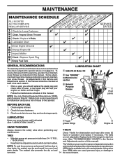
... (auxiliary) starter handle - used for starting engine. used for starting a cold engine. OPERATION SAFETY IGNITION KEY SPARK PLUG CHOKE CONTROL ENGINE OIL CAP WITH DIPSTICK AUGER CONTROL LEVER DISCHARGE CHUTE CONTROL LEVER DRIVE SPEED CONTROL LEVER DEFLECTOR REMOTE CONTROL LEVER GASOLINE FILLER CAP CHUTE DEFLECTOR FUEL SHUT-OFF VALVE TRACTION DRIVE CONTROL LEVER THROTTLE / ENGINE CONTROL DISCHARGE CHUTE RECOIL (AUXILIARY) STARTER HANDLE POWER CORD PLUG ELECTRIC START OIL DRAIN PLUG BUTTON PRIMER CLEAN-OUT TOOL LH TURN TRIGGER LIGHT HANDLE KNOB NOTE...
... (auxiliary) starter handle - used for starting engine. used for starting a cold engine. OPERATION SAFETY IGNITION KEY SPARK PLUG CHOKE CONTROL ENGINE OIL CAP WITH DIPSTICK AUGER CONTROL LEVER DISCHARGE CHUTE CONTROL LEVER DRIVE SPEED CONTROL LEVER DEFLECTOR REMOTE CONTROL LEVER GASOLINE FILLER CAP CHUTE DEFLECTOR FUEL SHUT-OFF VALVE TRACTION DRIVE CONTROL LEVER THROTTLE / ENGINE CONTROL DISCHARGE CHUTE RECOIL (AUXILIARY) STARTER HANDLE POWER CORD PLUG ELECTRIC START OIL DRAIN PLUG BUTTON PRIMER CLEAN-OUT TOOL LH TURN TRIGGER LIGHT HANDLE KNOB NOTE...

User Manual
Page 10
... desired position. Always operate the snow thrower with the engine at all times including startup. OFF FULL FIG. 13 TO CONTROL SNOW DISCHARGE (See Fig. 14) WARNING: Snow throwers have exposed rotating parts, which snow is to start a warm engine. • To engage choke, turn knob counterclockwise to lower the deflector and decrease the distance. Be sure lever springs back and locks into desired position. AUGER • Release the auger control lever to prevent unauthorized use...
... desired position. Always operate the snow thrower with the engine at all times including startup. OFF FULL FIG. 13 TO CONTROL SNOW DISCHARGE (See Fig. 14) WARNING: Snow throwers have exposed rotating parts, which snow is to start a warm engine. • To engage choke, turn knob counterclockwise to lower the deflector and decrease the distance. Be sure lever springs back and locks into desired position. AUGER • Release the auger control lever to prevent unauthorized use...

User Manual
Page 11
... auger control lever located on the speed control lever and move speed control lever when traction drive control lever is engaged. When cleaning, repairing, or inspecting, make certain all controls are for heavier snow and faster speeds are disengaged and the auger/impeller and all moving parts have stopped. Disconnect the spark plug wire and keep the wire away from the spark plug to prevent accidental starting. • Release the auger control lever and shut off the engine. • Remove the clean-out tool...
... auger control lever located on the speed control lever and move speed control lever when traction drive control lever is engaged. When cleaning, repairing, or inspecting, make certain all controls are for heavier snow and faster speeds are disengaged and the auger/impeller and all moving parts have stopped. Disconnect the spark plug wire and keep the wire away from the spark plug to prevent accidental starting. • Release the auger control lever and shut off the engine. • Remove the clean-out tool...
User Manual
Page 12
... operated over gravel or rocky surfaces. Never use gasoline near an open flame. Replace a damaged or worn scraper bar. 12 GASOLINE FILLER CAP FUEL SHUTOFF VALVE RECOIL STARTER HANDLE STARTER BUTTON POWER CORD PLUG NOTE: ALL ITEMS ARE SHOWN IN THEIR TYPICAL LOCATION. Use fresh, clean, regular unleaded gasoline with gasoline. See Storage Instructions for a few seconds, remove and read oil level. CHOKE CONTROL THROTTLE PRIMER ENGINE OIL FILL CAP / DIPSTICK HIGH POSITION (LOW GROUND CLEARANCE) SAFETY IGNITION KEY AUGER HOUSING HEX NUTS...
... operated over gravel or rocky surfaces. Never use gasoline near an open flame. Replace a damaged or worn scraper bar. 12 GASOLINE FILLER CAP FUEL SHUTOFF VALVE RECOIL STARTER HANDLE STARTER BUTTON POWER CORD PLUG NOTE: ALL ITEMS ARE SHOWN IN THEIR TYPICAL LOCATION. Use fresh, clean, regular unleaded gasoline with gasoline. See Storage Instructions for a few seconds, remove and read oil level. CHOKE CONTROL THROTTLE PRIMER ENGINE OIL FILL CAP / DIPSTICK HIGH POSITION (LOW GROUND CLEARANCE) SAFETY IGNITION KEY AUGER HOUSING HEX NUTS...

User Manual
Page 13
... drive speed control, NOT the throttle, to remove snow is the early morning. WARNING: Do not operate snow thrower if weather conditions impair visibility. electric starter and a recoil starter. WARNING: Do not use the electric starter if your house is a 120 Volt A.C. COLD START - DO NOT turn the key. Place throttle control in deep, freezing or heavy wet snow. Push the primer three (3) times. 7. When the engine starts, release the starter button and slowly move the choke control...
... drive speed control, NOT the throttle, to remove snow is the early morning. WARNING: Do not operate snow thrower if weather conditions impair visibility. electric starter and a recoil starter. WARNING: Do not use the electric starter if your house is a 120 Volt A.C. COLD START - DO NOT turn the key. Place throttle control in deep, freezing or heavy wet snow. Push the primer three (3) times. 7. When the engine starts, release the starter button and slowly move the choke control...
User Manual
Page 14
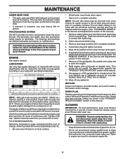
... operator. Check for deterioration and wear after every 50 TIRES • Maintain proper air pressure in the Service and Adjustments section of this unit. Auger grease fittings Engine oil SNOW THROWER Always observe the safety rules when performing any V-BELTS maintenance. Replace belts if they are not adjustable. A new spark plug will need to be checked at least once each season. • Once a year, you should replace the spark plug and check belts for wear. Using other parts dealer. MAINTENANCE...
... operator. Check for deterioration and wear after every 50 TIRES • Maintain proper air pressure in the Service and Adjustments section of this unit. Auger grease fittings Engine oil SNOW THROWER Always observe the safety rules when performing any V-BELTS maintenance. Replace belts if they are not adjustable. A new spark plug will need to be checked at least once each season. • Once a year, you should replace the spark plug and check belts for wear. Using other parts dealer. MAINTENANCE...
User Manual
Page 15
... pin into proper hole in wheel axle (See "TO REMOVE WHEELS" in contact with the left wheel removed, will drain more frequently to enter the engine. 8. Remove oil fill cap/dipstick. For approximate capacity see "PRODUCT SPECIFICATIONS" section of any spilled oil from running low on oil fill cap/dipstick for 25 hours in the Service and Adjustments section of each time you check the oil level. Be sure dipstick cap is required, use . Spark plug type and gap setting...
... pin into proper hole in wheel axle (See "TO REMOVE WHEELS" in contact with the left wheel removed, will drain more frequently to enter the engine. 8. Remove oil fill cap/dipstick. For approximate capacity see "PRODUCT SPECIFICATIONS" section of any spilled oil from running low on oil fill cap/dipstick for 25 hours in the Service and Adjustments section of each time you check the oil level. Be sure dipstick cap is required, use . Spark plug type and gap setting...
User Manual
Page 16
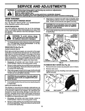
... Disengage all controls and move throttle control to the top of this manual. Install 1/4-20 lock nut and tighten securely. 3. Remove the two screws securing belt cover to the auger shaft with holes in STOP position. 2. If impeller does not turn when auger control lever is in impeller shaft and install two (2) new 1/4-20 x 1-5/8" capscrew/shear bolts. Disconnect spark plug wire from the operator. CHUTE DEFLECTOR The chute deflector, attached to STOP position. Remove safety ignition key and disconnect spark plug wire from spark plug. SERVICE AND ADJUSTMENTS WARNING...
... Disengage all controls and move throttle control to the top of this manual. Install 1/4-20 lock nut and tighten securely. 3. Remove the two screws securing belt cover to the auger shaft with holes in STOP position. 2. If impeller does not turn when auger control lever is in impeller shaft and install two (2) new 1/4-20 x 1-5/8" capscrew/shear bolts. Disconnect spark plug wire from the operator. CHUTE DEFLECTOR The chute deflector, attached to STOP position. Remove safety ignition key and disconnect spark plug wire from spark plug. SERVICE AND ADJUSTMENTS WARNING...
User Manual
Page 17
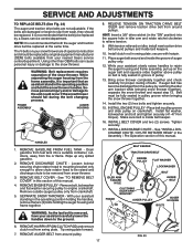
... CHUTE / CHUTE ROTATER HEAD" in the Assembly / Pre-Operation section of this manual. 4. INSTALL ENGINE PULLEY - WARNING: Belt replacement requires separation of belts. Drain gasoline from fuel tank into the square hole in idler arm and rotate ratchet clockwise to the ground. 6. BELT KEEPER TRACTION DRIVE BELT ENGINE PULLEY FLAT WASHER LOCKWASHER IDLER ARM SQUARE HOLE BOLT AUGER BELT FRAME CLUTCHING IDLER ARM BRACKET AUGER PULLEY AUGER HOUSING BOLTS WARNING: As the last bolt is inside belt keeper. 16. SERVICE AND ADJUSTMENTS TO REPLACE BELTS...
... CHUTE / CHUTE ROTATER HEAD" in the Assembly / Pre-Operation section of this manual. 4. INSTALL ENGINE PULLEY - WARNING: Belt replacement requires separation of belts. Drain gasoline from fuel tank into the square hole in idler arm and rotate ratchet clockwise to the ground. 6. BELT KEEPER TRACTION DRIVE BELT ENGINE PULLEY FLAT WASHER LOCKWASHER IDLER ARM SQUARE HOLE BOLT AUGER BELT FRAME CLUTCHING IDLER ARM BRACKET AUGER PULLEY AUGER HOUSING BOLTS WARNING: As the last bolt is inside belt keeper. 16. SERVICE AND ADJUSTMENTS TO REPLACE BELTS...
User Manual
Page 18
... before painting. Pull recoil starter handle slowly a few times to be stored for a period of acids during storage. SNOW THROWER When snow thrower is to distribute oil. 4. ENGINE See engine manual. FUEL SYSTEM IMPORTANT: It is factory set for pushing or transporting the snow thrower), remove klik pin from wheel hub and insert pin into cylinder. 3. Also, alcohol blended fuels (called gasohol or using fuel stabilizer. Do not drain the gas tank and carburetor if using ethanol or...
... before painting. Pull recoil starter handle slowly a few times to be stored for a period of acids during storage. SNOW THROWER When snow thrower is to distribute oil. 4. ENGINE See engine manual. FUEL SYSTEM IMPORTANT: It is factory set for pushing or transporting the snow thrower), remove klik pin from wheel hub and insert pin into cylinder. 3. Also, alcohol blended fuels (called gasohol or using fuel stabilizer. Do not drain the gas tank and carburetor if using ethanol or...
User Manual
Page 19
... power 1. Clogged discharge chute. 4. Reconnect spark plug wire. 2. Choke is off valve to rust. Stale fuel. 4. Loose parts or damaged augers or impeller. 1. Auger belt is in need of pulley. 2. Augers / impeller jammed. 1. STORAGE OTHER • Remove safety ignition key; store it in STOP position. 5. Throttle in a safe place. • Do not store gasoline from augers / impeller. 19 Empty fuel tank & carburetor, refill with ice or snow. 4. Engine idles or runs roughly 1. Throwing too much snow. 3. Contact a qualified service...
... power 1. Clogged discharge chute. 4. Reconnect spark plug wire. 2. Choke is off valve to rust. Stale fuel. 4. Loose parts or damaged augers or impeller. 1. Auger belt is in need of pulley. 2. Augers / impeller jammed. 1. STORAGE OTHER • Remove safety ignition key; store it in STOP position. 5. Throttle in a safe place. • Do not store gasoline from augers / impeller. 19 Empty fuel tank & carburetor, refill with ice or snow. 4. Engine idles or runs roughly 1. Throwing too much snow. 3. Contact a qualified service...

User Manual
Page 41
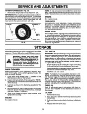
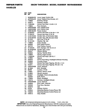
MODEL NUMBER 96194000600 CONTROL PANEL / DISCHARGE CHUTE KEY PART NO. Failure to do so could be hazardous, damage your snow thrower and void your warranty. 41 REPAIR PARTS SNOW THROWER - NO. inches. 1 inch = 25.4 mm IMPORTANT: Use only Original Equipment Manufacturer (O.E.M.) replacement parts. DESCRIPTION 1 414280 Knob, Lever 2 17501010 Screw #10-24 x 5/8 3 198475 Control Assembly, Deflector 4 73800600 Nut, Lock 3/8-16 5 19131316 Washer, Flat 3/8 6 404974 Control Assembly, Chute Rotator 7 405784X479 Support, Pivot 8 150078 Screw, Hex Head 5/16-18 x 3/4 9 184505 Spring, ...
MODEL NUMBER 96194000600 CONTROL PANEL / DISCHARGE CHUTE KEY PART NO. Failure to do so could be hazardous, damage your snow thrower and void your warranty. 41 REPAIR PARTS SNOW THROWER - NO. inches. 1 inch = 25.4 mm IMPORTANT: Use only Original Equipment Manufacturer (O.E.M.) replacement parts. DESCRIPTION 1 414280 Knob, Lever 2 17501010 Screw #10-24 x 5/8 3 198475 Control Assembly, Deflector 4 73800600 Nut, Lock 3/8-16 5 19131316 Washer, Flat 3/8 6 404974 Control Assembly, Chute Rotator 7 405784X479 Support, Pivot 8 150078 Screw, Hex Head 5/16-18 x 3/4 9 184505 Spring, ...
User Manual
Page 43
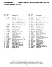
... 72120618 Bolt, Carriage 3/8-16 x 2-1/4 23 401940X479 Handle Tube, Lower 24 180447 Sleeve, Spring 25 180926 Spring, Traction Drive 26 178669 Spring, Auger Control 27 17000616 Screw, Hex Head 3/8-16 x 1 28 412680 Spacer 29 408059 Screw, Grounding, Headlight to do so could be hazardous, damage your snow thrower and void your warranty. 43 MODEL NUMBER 96194000600 KEY PART NO. NO. inches. 1 inch = 25.4 mm IMPORTANT: Use only Original Equipment Manufacturer (O.E.M.) replacement parts. REPAIR PARTS HANDLES SNOW THROWER - Failure to Blower Housing...
... 72120618 Bolt, Carriage 3/8-16 x 2-1/4 23 401940X479 Handle Tube, Lower 24 180447 Sleeve, Spring 25 180926 Spring, Traction Drive 26 178669 Spring, Auger Control 27 17000616 Screw, Hex Head 3/8-16 x 1 28 412680 Spacer 29 408059 Screw, Grounding, Headlight to do so could be hazardous, damage your snow thrower and void your warranty. 43 MODEL NUMBER 96194000600 KEY PART NO. NO. inches. 1 inch = 25.4 mm IMPORTANT: Use only Original Equipment Manufacturer (O.E.M.) replacement parts. REPAIR PARTS HANDLES SNOW THROWER - Failure to Blower Housing...

User Manual
Page 45
inches. 1 inch = 25.4 mm IMPORTANT: Use only Original Equipment Manufacturer (O.E.M.) replacement parts. MODEL NUMBER 96194000600 KEY PART NO. Failure to do so could be hazardous, damage your snow thrower and void your warranty. 45 REPAIR PARTS DRIVE SNOW THROWER - NO. DESCRIPTION 1 401619 Chain, Drive 2 751153 Nut, Lock 5/16-18 3 402882 Clip, Retainer 4 17490508 Bolt, Hex Head 5/16-18 x 1/2 5 408981 Bearing, Flange 6 12000007 E-Ring, Retainer 9 402855 Sprocket & Shaft Assembly 11 402568 Rod, Clutch 12 402187 Shaft, Hex 13 402310...
inches. 1 inch = 25.4 mm IMPORTANT: Use only Original Equipment Manufacturer (O.E.M.) replacement parts. MODEL NUMBER 96194000600 KEY PART NO. Failure to do so could be hazardous, damage your snow thrower and void your warranty. 45 REPAIR PARTS DRIVE SNOW THROWER - NO. DESCRIPTION 1 401619 Chain, Drive 2 751153 Nut, Lock 5/16-18 3 402882 Clip, Retainer 4 17490508 Bolt, Hex Head 5/16-18 x 1/2 5 408981 Bearing, Flange 6 12000007 E-Ring, Retainer 9 402855 Sprocket & Shaft Assembly 11 402568 Rod, Clutch 12 402187 Shaft, Hex 13 402310...
User Manual
Page 47
REPAIR PARTS SNOW THROWER - DESCRIPTION 1 414557 Spring, Traction Idler 2 180522 Pulley, Idler (2-1/4) 3 --- MODEL NUMBER 96194000600 CHASSIS / ENGINE / PULLEYS KEY PART NO. Failure to do so could be hazardous, damage your snow thrower and void your warranty. 47 Engine, Tecumseh, Model Number LH358SA (For engine service and replacement parts, call Tecumseh Products at 1-800-558-5402) 4 74780520 Screw, Hex Head 5/16-18 x 1-1/4 5 150078 Screw 6 59289 Washer, Flat 7 166785 Nut, Jam, Lock 5/16-18 8 175330 Pin, Idler Pivot 9 416954 V-Belt, Traction Drive 10...
REPAIR PARTS SNOW THROWER - DESCRIPTION 1 414557 Spring, Traction Idler 2 180522 Pulley, Idler (2-1/4) 3 --- MODEL NUMBER 96194000600 CHASSIS / ENGINE / PULLEYS KEY PART NO. Failure to do so could be hazardous, damage your snow thrower and void your warranty. 47 Engine, Tecumseh, Model Number LH358SA (For engine service and replacement parts, call Tecumseh Products at 1-800-558-5402) 4 74780520 Screw, Hex Head 5/16-18 x 1-1/4 5 150078 Screw 6 59289 Washer, Flat 7 166785 Nut, Jam, Lock 5/16-18 8 175330 Pin, Idler Pivot 9 416954 V-Belt, Traction Drive 10...

User Manual
Page 52
... the product. 5. This Warranty is requested by the original consumer purchaser, we find to be paid by the purchaser unless such return is subject to normal wear of any part which vary from defects in replacing parts, any power equipment unit or attachment are belts, shear pins, normal wear, normal adjustments, standard hardware and normal maintenance. 6. ID#, serial number and date of purchase...
... the product. 5. This Warranty is requested by the original consumer purchaser, we find to be paid by the purchaser unless such return is subject to normal wear of any part which vary from defects in replacing parts, any power equipment unit or attachment are belts, shear pins, normal wear, normal adjustments, standard hardware and normal maintenance. 6. ID#, serial number and date of purchase...


