
Service Manual
Page 1
2006 LCD Models FLM-2632, FLM-2632M, FLM-2634B, FLM-3232, FLM-3232M, FLM-323B, FLM-3234B, FLM-3732, FLM-3732M, FLM-373B, FLM-3734B, FLX-374 SERVICE MANUAL Bezel covers vary by model 20070411
2006 LCD Models FLM-2632, FLM-2632M, FLM-2634B, FLM-3232, FLM-3232M, FLM-323B, FLM-3234B, FLM-3732, FLM-3732M, FLM-373B, FLM-3734B, FLX-374 SERVICE MANUAL Bezel covers vary by model 20070411
Service Manual
Page 5
... Charts ...14 3. PCB Layout Diagrams ...51 Model Specifications are located in User Manual. Polaroid Display Cell Defect Specification 18 4. Before Returning This Product to obtain User Manual. 5 FLM-Series 26, 32, 37 32 7. Schematics ...43 10. Operation ...6 2. Block Diagram - Disassembly Procedure...20 Rear Cover Removal ...21 Rear Cabinet Cover LCD Panel and Front Bezel 23 A/V Board...
... Charts ...14 3. PCB Layout Diagrams ...51 Model Specifications are located in User Manual. Polaroid Display Cell Defect Specification 18 4. Before Returning This Product to obtain User Manual. 5 FLM-Series 26, 32, 37 32 7. Schematics ...43 10. Operation ...6 2. Block Diagram - Disassembly Procedure...20 Rear Cover Removal ...21 Rear Cabinet Cover LCD Panel and Front Bezel 23 A/V Board...

Service Manual
Page 19
... proper installation, including non-metallic controls, insulation materials, cabinet backs, compartment covers, and shields. (3) Verify that no wires are pinched between revisions of the same model, so always conduct a thorough review of the chassis, especially any metal parts. (2) Inspect all exposed metallic parts and a known earth ground. Use the following safety...
... proper installation, including non-metallic controls, insulation materials, cabinet backs, compartment covers, and shields. (3) Verify that no wires are pinched between revisions of the same model, so always conduct a thorough review of the chassis, especially any metal parts. (2) Inspect all exposed metallic parts and a known earth ground. Use the following safety...
Service Manual
Page 21
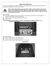
...within all system boards to protect the front bezel and LCD screen from being scratched. Be careful to protect the front bezel and LCD screen from the wall outlet. Stand Removal (1) Lay TV flat on workbench. Note: Before disassembly of TV and lift off. 21 Rear Cover Removal (4) Remove ... (PIC1 item 3) (6) Remove control box cover- Rear Cover Removal Lay TV flat on workbench. Never insert any part the TV, make sure the power is OFF, and the power cord is a 26" model. 32" and 37" models will have different stand screw quantities and locations. slide toward bottom of any...
...within all system boards to protect the front bezel and LCD screen from being scratched. Be careful to protect the front bezel and LCD screen from the wall outlet. Stand Removal (1) Lay TV flat on workbench. Note: Before disassembly of TV and lift off. 21 Rear Cover Removal (4) Remove ... (PIC1 item 3) (6) Remove control box cover- Rear Cover Removal Lay TV flat on workbench. Never insert any part the TV, make sure the power is OFF, and the power cord is a 26" model. 32" and 37" models will have different stand screw quantities and locations. slide toward bottom of any...
Service Manual
Page 23
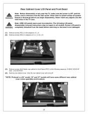
... the bezel is a 26" model. 32" and 37" models will come off. *NOTE: Pictured is not damaged. (1) Remove screws (PIC1) in the sequence of 1, A. (2) Remove screws (PIC1) in sequence of any objects into the vent holes in production. Never insert any part the TV, make sure the power is OFF... is removed from the bezel before you begin disassembly. Allow time for power within all models. Note: OEM LCD panels were used in the TV case. The following LCD panel disassembly/removal instructions may not apply to all system boards to front frame (PIC1) in the following sequence: AÆBÆ...
... the bezel is a 26" model. 32" and 37" models will come off. *NOTE: Pictured is not damaged. (1) Remove screws (PIC1) in the sequence of 1, A. (2) Remove screws (PIC1) in sequence of any objects into the vent holes in production. Never insert any part the TV, make sure the power is OFF... is removed from the bezel before you begin disassembly. Allow time for power within all models. Note: OEM LCD panels were used in the TV case. The following LCD panel disassembly/removal instructions may not apply to all system boards to front frame (PIC1) in the following sequence: AÆBÆ...

Service Manual
Page 32
...by AC plug, perform a clear or reset in the spare part lists with R. The TV serial number Model Version is not present in Year of Production is the Polaroid serial number format breakdown with multiple versions. the 0 in the part lists please review service ...bulletins for repair. Spare Parts Lists - FLM-Series 26, 32, 37 Attention Service Centers Some models consist of Production Model Version SAMPLE SERIAL NUMBER FORMAT - Service bulletins can be obtained through your Polaroid service contact. DETAILS 06 00 01 272 0000001 Unique 7 digit...
...by AC plug, perform a clear or reset in the spare part lists with R. The TV serial number Model Version is not present in Year of Production is the Polaroid serial number format breakdown with multiple versions. the 0 in the part lists please review service ...bulletins for repair. Spare Parts Lists - FLM-Series 26, 32, 37 Attention Service Centers Some models consist of Production Model Version SAMPLE SERIAL NUMBER FORMAT - Service bulletins can be obtained through your Polaroid service contact. DETAILS 06 00 01 272 0000001 Unique 7 digit...


