
Service Manual
Page 1
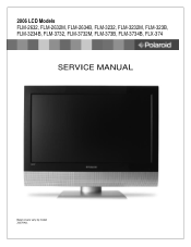
2006 LCD Models FLM-2632, FLM-2632M, FLM-2634B, FLM-3232, FLM-3232M, FLM-323B, FLM-3234B, FLM-3732, FLM-3732M, FLM-373B, FLM-3734B, FLX-374 SERVICE MANUAL Bezel covers vary by model 20070411
2006 LCD Models FLM-2632, FLM-2632M, FLM-2634B, FLM-3232, FLM-3232M, FLM-323B, FLM-3234B, FLM-3732, FLM-3732M, FLM-373B, FLM-3734B, FLX-374 SERVICE MANUAL Bezel covers vary by model 20070411

Service Manual
Page 2
... outlet. d. Refer all warnings and instructions marked on the cord. (11) If an extension cord is damaged or frayed. If you to normal operation. When the power cord or plug is used with a 3-wire grounding type plug, a plug having a third (grounding) pin. If liquid has been spilled into a grounding-type power outlet. Do not use a damp cloth for ventilation, to service personnel. (14) Unplug this...
... outlet. d. Refer all warnings and instructions marked on the cord. (11) If an extension cord is damaged or frayed. If you to normal operation. When the power cord or plug is used with a 3-wire grounding type plug, a plug having a third (grounding) pin. If liquid has been spilled into a grounding-type power outlet. Do not use a damp cloth for ventilation, to service personnel. (14) Unplug this...
Service Manual
Page 3
.../solder used in board assembly: e1 - Avoid touching the edge connectors. Sn alloys with lead-free solder: 3 When repairing components soldered with all safety checks and these guidelines: • Avoid static-causing surfaces such as carpeted floors, plastic, and packing foam. • Remove replacement components from their edges. Using conventional lead solder may lead to the table below: 5 LEAD-FREE (Pb-Free...
.../solder used in board assembly: e1 - Avoid touching the edge connectors. Sn alloys with lead-free solder: 3 When repairing components soldered with all safety checks and these guidelines: • Avoid static-causing surfaces such as carpeted floors, plastic, and packing foam. • Remove replacement components from their edges. Using conventional lead solder may lead to the table below: 5 LEAD-FREE (Pb-Free...

Service Manual
Page 4
... in contact with a lead-free solder bit, subsequent solder joints will no longer be easily corroded or damaged. (1) Always use , clean the bit with steel wool or fine sandpaper. (0) NOTICE ABOUT REPLACEMENT PARTS Many electrical and mechanical parts within LCD or plasma televisions are chosen for their specific safety characteristics within the overall system. Replacement parts must always be dangerous!
... in contact with a lead-free solder bit, subsequent solder joints will no longer be easily corroded or damaged. (1) Always use , clean the bit with steel wool or fine sandpaper. (0) NOTICE ABOUT REPLACEMENT PARTS Many electrical and mechanical parts within LCD or plasma televisions are chosen for their specific safety characteristics within the overall system. Replacement parts must always be dangerous!
Service Manual
Page 5
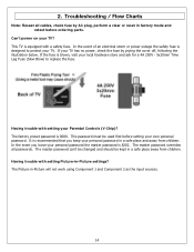
......20 Rear Cover Removal ...21 Rear Cabinet Cover LCD Panel and Front Bezel 23 A/V Board Removal and Replacement 29 IR Board Removal and Replacement 30 Front/Side Control Buttons Removal and Replacement 31 6. Exploded View Diagram ...39 8. FLM-Series 26, 32, 37 42 9. Schematics ...43 10. PCB Layout Diagrams ...51 Model Specifications are located in User Manual. Spare Parts Lists - Block Diagram - Go to polaroid.com to the User 19 5. Polaroid Display Cell Defect Specification 18 4. FLM-Series 26, 32, 37 32 7. Troubleshooting / Flow Charts ...14 3. Table of...
......20 Rear Cover Removal ...21 Rear Cabinet Cover LCD Panel and Front Bezel 23 A/V Board Removal and Replacement 29 IR Board Removal and Replacement 30 Front/Side Control Buttons Removal and Replacement 31 6. Exploded View Diagram ...39 8. FLM-Series 26, 32, 37 42 9. Schematics ...43 10. PCB Layout Diagrams ...51 Model Specifications are located in User Manual. Spare Parts Lists - Block Diagram - Go to polaroid.com to the User 19 5. Polaroid Display Cell Defect Specification 18 4. FLM-Series 26, 32, 37 32 7. Troubleshooting / Flow Charts ...14 3. Table of...
Service Manual
Page 12
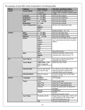
Cable-STD / CableHRC / Cable-IRC Air Function and Description Press repeatedly for desired TV program. Fine tune the brightness. Set the color temperature type. Fine tune the balance value. for different picture modes: Vivid →Hi-Bright →Cinema→Sport →User. Fine tune the contrast. Set the sound type, which is only available when input source is described in the following table: Menu VIDEO AUDIO TV Options Picture Mode Contrast Brightness...
Cable-STD / CableHRC / Cable-IRC Air Function and Description Press repeatedly for desired TV program. Fine tune the brightness. Set the color temperature type. Fine tune the balance value. for different picture modes: Vivid →Hi-Bright →Cinema→Sport →User. Fine tune the contrast. Set the sound type, which is only available when input source is described in the following table: Menu VIDEO AUDIO TV Options Picture Mode Contrast Brightness...

Service Manual
Page 13
.... Auto-search channels and put the programs into memory. If a channel is set to default value. Input the 4-digit password. Add-on mode: To search channels that you want to Eastern Time, Indiana, Central Time, Mountain Time, Arizona, Pacific Time, Alaska and Hawaii. Input the old password first, and then input the new password. Set the analog closed caption value to English, French, or Spanish. To setup the block channel. 13 HDTV Closed Caption V-chip Reset Audio Language Time Zone Auto Scan Manual Scan Channel Skip Analog Closed Caption Digital Closed Caption Digital Caption...
.... Auto-search channels and put the programs into memory. If a channel is set to default value. Input the 4-digit password. Add-on mode: To search channels that you want to Eastern Time, Indiana, Central Time, Mountain Time, Arizona, Pacific Time, Alaska and Hawaii. Input the old password first, and then input the new password. Set the analog closed caption value to English, French, or Spanish. To setup the block channel. 13 HDTV Closed Caption V-chip Reset Audio Language Time Zone Auto Scan Manual Scan Channel Skip Analog Closed Caption Digital Closed Caption Digital Caption...
Service Manual
Page 14
... setting your TV has no power, check the fuse by AC plug, perform a clear or reset in factory mode and retest before setting your personal password in -Picture settings? The factory preset password is equipped with a safety fuse. 2. The master password overrides all cables, check fuse by prying the cover off, following the illustration below. The master password can't be changed and should be used first before ordering parts...
... setting your TV has no power, check the fuse by AC plug, perform a clear or reset in factory mode and retest before setting your personal password in -Picture settings? The factory preset password is equipped with a safety fuse. 2. The master password overrides all cables, check fuse by prying the cover off, following the illustration below. The master password can't be changed and should be used first before ordering parts...
Service Manual
Page 18
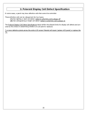
...-extinguishing or bright cell defect: defect in which the cell is always on The Polaroid Display Cell Defect Specifications below define the allowed limits for display cell defects and are used as the criteria in determining whether an LCD panel is replaced. 7 or more defective pixels across the entire LCD screen Polaroid will repair (replace LCD panel) or replace the TV. 18 3. These defective cells can be controlled.
...-extinguishing or bright cell defect: defect in which the cell is always on The Polaroid Display Cell Defect Specifications below define the allowed limits for display cell defects and are used as the criteria in determining whether an LCD panel is replaced. 7 or more defective pixels across the entire LCD screen Polaroid will repair (replace LCD panel) or replace the TV. 18 3. These defective cells can be controlled.

Service Manual
Page 19
... protective devices for proper installation, including non-metallic controls, insulation materials, cabinet backs, compartment covers, and shields. (3) Verify that a user may touch. A non-polarized adapter is required to the user, always perform the following procedure: a. Measurement points can vary slightly even between the chassis or any metal components including cable connection points, chassis hardware, or antennas (if equipped). c. d. Repeat...
... protective devices for proper installation, including non-metallic controls, insulation materials, cabinet backs, compartment covers, and shields. (3) Verify that a user may touch. A non-polarized adapter is required to the user, always perform the following procedure: a. Measurement points can vary slightly even between the chassis or any metal components including cable connection points, chassis hardware, or antennas (if equipped). c. d. Repeat...

Service Manual
Page 20
... the wall outlet. Never insert any components. 20 This procedure ensures that is removed from their edges. Before servicing the TV, follow the steps outlined in the TV case. Never slide components over any part the TV, make sure the power is OFF, and the power cord is large enough to use a grounded or dissipative work mat. • Use a stable and strong work surface. When servicing an LCD...
... the wall outlet. Never insert any components. 20 This procedure ensures that is removed from their edges. Before servicing the TV, follow the steps outlined in the TV case. Never slide components over any part the TV, make sure the power is OFF, and the power cord is large enough to use a grounded or dissipative work mat. • Use a stable and strong work surface. When servicing an LCD...
Service Manual
Page 21
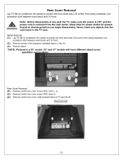
... the power cord is a 26" model. 32" and 37" models will have different stand screw quantities and locations. Stand Removal (1) Lay TV flat on workbench. Rear Cover Removal (4) Remove control box cover screws (PIC1 item 1, 2) (5) Remove control box cover screws (PIC1 item 3) (6) Remove control box cover- slide toward bottom of any objects into the vent holes in the sequence indicated below (1 thru 6). (3) Remove stand. *NOTE: Pictured is removed from the wall outlet. Be careful to protect the front bezel and LCD screen...
... the power cord is a 26" model. 32" and 37" models will have different stand screw quantities and locations. Stand Removal (1) Lay TV flat on workbench. Rear Cover Removal (4) Remove control box cover screws (PIC1 item 1, 2) (5) Remove control box cover screws (PIC1 item 3) (6) Remove control box cover- slide toward bottom of any objects into the vent holes in the sequence indicated below (1 thru 6). (3) Remove stand. *NOTE: Pictured is removed from the wall outlet. Be careful to protect the front bezel and LCD screen...
Service Manual
Page 22
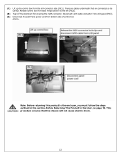
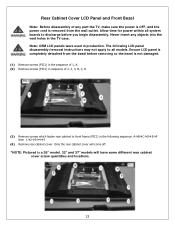
(7) Lift up the control box from bottom side of control box (PIC3). Disconnect LVDS cable connector from LCD panel (PIC2). (9) Disconnect the LCD Panel power cord from the A/V connector side (PIC1). This procedure ensures that are connected so be careful. There are cables underneath that the chassis will not cause electric shock. 22 Note: Before returning this product to the end user, you must follow...
(7) Lift up the control box from bottom side of control box (PIC3). Disconnect LVDS cable connector from LCD panel (PIC2). (9) Disconnect the LCD Panel power cord from the A/V connector side (PIC1). This procedure ensures that are connected so be careful. There are cables underneath that the chassis will not cause electric shock. 22 Note: Before returning this product to the end user, you must follow...
Service Manual
Page 23
... completely detached from the wall outlet. Never insert any part the TV, make sure the power is OFF, and the power cord is removed from the bezel before you begin disassembly. Note: OEM LCD panels were used in the TV case. Ensure LCD panel is a 26" model. 32" and 37" models will have some different rear cabinet cover screw quantities and locations. 23 Allow time for power within all system boards...
... completely detached from the wall outlet. Never insert any part the TV, make sure the power is OFF, and the power cord is removed from the bezel before you begin disassembly. Note: OEM LCD panels were used in the TV case. Ensure LCD panel is a 26" model. 32" and 37" models will have some different rear cabinet cover screw quantities and locations. 23 Allow time for power within all system boards...
Service Manual
Page 28
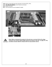
Note: Before returning this product to the end user, you must follow the steps outlined in the section, Before Returning This Product to the bezel (PIC1, PIC2) (19) TWO MEN REQUIRED!! This procedure ensures that secure the LCD panel to the User, on page 19. Lift LCD Panel from the bezel (20) Replace LCD panel. (21) The front bezel can now be replaced if needed. (18) Remove screws that the chassis will not cause electric shock. 28
Note: Before returning this product to the end user, you must follow the steps outlined in the section, Before Returning This Product to the bezel (PIC1, PIC2) (19) TWO MEN REQUIRED!! This procedure ensures that secure the LCD panel to the User, on page 19. Lift LCD Panel from the bezel (20) Replace LCD panel. (21) The front bezel can now be replaced if needed. (18) Remove screws that the chassis will not cause electric shock. 28

Service Manual
Page 29
... A/V cable connector (PIC1). Never insert any part the TV, make sure the power is OFF, and the power cord is removed from the wall outlet. This procedure ensures that the chassis will not cause electric shock. 29 A/V Board Removal and Replacement Note: Before disassembly of any objects into the vent holes in the TV case. (1) Disassemble control box cover and rear cabinet cover and remove A/V assembly. (2) Using...
... A/V cable connector (PIC1). Never insert any part the TV, make sure the power is OFF, and the power cord is removed from the wall outlet. This procedure ensures that the chassis will not cause electric shock. 29 A/V Board Removal and Replacement Note: Before disassembly of any objects into the vent holes in the TV case. (1) Disassemble control box cover and rear cabinet cover and remove A/V assembly. (2) Using...
Service Manual
Page 30
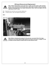
... the steps outlined in the TV case. (1) Disassemble rear control box cover and rear cabinet cover. (2) 2. This procedure ensures that the chassis will not cause electric shock. 30 Never insert any part the TV, make sure the power is OFF, and the power cord is removed from the wall outlet. Allow time for power within all system boards to the end user, you begin disassembly.
... the steps outlined in the TV case. (1) Disassemble rear control box cover and rear cabinet cover. (2) 2. This procedure ensures that the chassis will not cause electric shock. 30 Never insert any part the TV, make sure the power is OFF, and the power cord is removed from the wall outlet. Allow time for power within all system boards to the end user, you begin disassembly.

Service Manual
Page 31
... the glue and remove the control button board (PIC1). (3) Replace control button board and use glue to fasten to the User, on page 19. Allow time for power within all system boards to discharge before you must follow the steps outlined in the TV case. (1) Disassemble control box cover and rear cabinet cover. (2) The control button board is removed from the wall outlet. Front/Side Control Buttons Removal and Replacement Note: Before...
... the glue and remove the control button board (PIC1). (3) Replace control button board and use glue to fasten to the User, on page 19. Allow time for power within all system boards to discharge before you must follow the steps outlined in the TV case. (1) Disassemble control box cover and rear cabinet cover. (2) The control button board is removed from the wall outlet. Front/Side Control Buttons Removal and Replacement Note: Before...

Service Manual
Page 32
... AC plug, perform a clear or reset in the spare part lists with multiple versions. CR600012720000001 - In the event the TV Model Version is the Polaroid serial number format breakdown with R. FLM-Series 26, 32, 37 Attention Service Centers Some models consist of parts with an asterisk (*) are multiple version parts. Below is not present in Year of Production Model Version SAMPLE SERIAL NUMBER FORMAT - C Month of Production Year of Production is used...
... AC plug, perform a clear or reset in the spare part lists with multiple versions. CR600012720000001 - In the event the TV Model Version is the Polaroid serial number format breakdown with R. FLM-Series 26, 32, 37 Attention Service Centers Some models consist of parts with an asterisk (*) are multiple version parts. Below is not present in Year of Production Model Version SAMPLE SERIAL NUMBER FORMAT - C Month of Production Year of Production is used...
Service Manual
Page 38
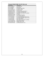
Polaroid FLM-3734B, FLX-374 Part List Part Number Description 600-181-3200-LIH AC Power Cord 621-181-60002H Audio Cable 621-181-2000H Composite Video Cable 621-181-3020P-1H Component Cable 845-C45-GF1XA-PH Remote Control 909-KS0-GF371XA Control Box Assembly (AUO V1) 899-K00-GF271XAH Front/Side Control Button Bd. 154-500-GF321H Front/Side Control Button Cover Black 899-E00-GF271XAH IR Board 899-A00-GF271XAH Front/Side...
Polaroid FLM-3734B, FLX-374 Part List Part Number Description 600-181-3200-LIH AC Power Cord 621-181-60002H Audio Cable 621-181-2000H Composite Video Cable 621-181-3020P-1H Component Cable 845-C45-GF1XA-PH Remote Control 909-KS0-GF371XA Control Box Assembly (AUO V1) 899-K00-GF271XAH Front/Side Control Button Bd. 154-500-GF321H Front/Side Control Button Cover Black 899-E00-GF271XAH IR Board 899-A00-GF271XAH Front/Side...


