Service Manual
Page 2
...an unstable cart, stand or table. If liquid has been spilled into a grounding-type power outlet. If the product exhibits a distinct change in the user's manual for service. . 2 www.polaroid.com The openings should not be blocked by placing the product on the marketing label. ... Refer all the procedures outlined in performance, indicating a need for this product. (1) Read all of the product and to rest on the power cord. If the product has been exposed to qualified service personnel under the following conditions: (0) a. f. Important Service and Safety Information Prior to...
...an unstable cart, stand or table. If liquid has been spilled into a grounding-type power outlet. If the product exhibits a distinct change in the user's manual for service. . 2 www.polaroid.com The openings should not be blocked by placing the product on the marketing label. ... Refer all the procedures outlined in performance, indicating a need for this product. (1) Read all of the product and to rest on the power cord. If the product has been exposed to qualified service personnel under the following conditions: (0) a. f. Important Service and Safety Information Prior to...
Service Manual
Page 3
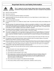
... rated for their specific safety characteristics within the overall system. Before servicing the TV, follow these service guidelines: ELECTRIC SHOCK HAZARD Always disconnect AC power before touching any surface. • Wear a grounding wrist strap (available at...only when you are sensitive to a bare metal part of antistatic bags because only the inside an LCD or plasma TV are ready to those originally used in fire, electric shock, or other grounded object before servicing!... a bare metal surface on your workbench or other hazards. 3 www.polaroid.com Never insert any circuit!
... rated for their specific safety characteristics within the overall system. Before servicing the TV, follow these service guidelines: ELECTRIC SHOCK HAZARD Always disconnect AC power before touching any surface. • Wear a grounding wrist strap (available at...only when you are sensitive to a bare metal part of antistatic bags because only the inside an LCD or plasma TV are ready to those originally used in fire, electric shock, or other grounded object before servicing!... a bare metal surface on your workbench or other hazards. 3 www.polaroid.com Never insert any circuit!

Service Manual
Page 4
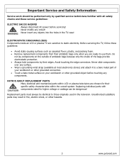
...good solder joint. Because the melting point of lead-free solder is blackened during use, clean the bit with steel wool or fine sandpaper. (0) 4 www.polaroid.com Whenever soldering, look at this television use . (2) Keep the soldering bit in category e2) e2 - low temperature solder (≤ 150 °C) ...material, and/or the solder paste/solder used in contact with no longer be lead free. contains Bi e7 - Do not leave the bit powered on the component. If a different type of solder. Leaving the bit in contact with lead-free solder: (1) Always use lead-free solder ...
...good solder joint. Because the melting point of lead-free solder is blackened during use, clean the bit with steel wool or fine sandpaper. (0) 4 www.polaroid.com Whenever soldering, look at this television use . (2) Keep the soldering bit in category e2) e2 - low temperature solder (≤ 150 °C) ...material, and/or the solder paste/solder used in contact with no longer be lead free. contains Bi e7 - Do not leave the bit powered on the component. If a different type of solder. Leaving the bit in contact with lead-free solder: (1) Always use lead-free solder ...

Service Manual
Page 9
... 60 15.734 625 50 15.625 525 60 625 50 15.734 15.625 HDTV/Component AV Timing SDTV 480p HDTV 720p HDTV 1080i Power Source 720x480 60 1280x720 60 1920x1080 60 AC100 - 240 V, 60/50 Hz 31.5 50.0 33.7 CLK MHz 25.16 31...
... 60 15.734 625 50 15.625 525 60 625 50 15.734 15.625 HDTV/Component AV Timing SDTV 480p HDTV 720p HDTV 1080i Power Source 720x480 60 1280x720 60 1920x1080 60 AC100 - 240 V, 60/50 Hz 31.5 50.0 33.7 CLK MHz 25.16 31...
Service Manual
Page 16
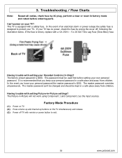
... event of an electrical storm or power outage the safety fuse is 0000. The factory preset password is designed to exit. 16 www.polaroid.com The master password overrides all cables, check fuse by prying the cover off TV with remote or power button to protect your personal password ...in factory mode and retest before setting your TV has no power, check the fuse by AC plug, perform...
... event of an electrical storm or power outage the safety fuse is 0000. The factory preset password is designed to exit. 16 www.polaroid.com The master password overrides all cables, check fuse by prying the cover off TV with remote or power button to protect your personal password ...in factory mode and retest before setting your TV has no power, check the fuse by AC plug, perform...
Service Manual
Page 22
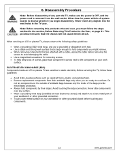
...that the chassis will not cause electric shock. Never slide components over any components. 22 www.polaroid.com 6. Note: Before returning this product to the end user, you are ready to ... Disassembly Procedure Note: Before disassembly of antistatic bags because only the inside an LCD or plasma TV are attached with a cable, unplug the cable before removing the screws to avoid damaging...; Always hold components you begin disassembly. Never insert any part the TV, make sure the power is OFF, and the power cord is large enough to hold components by their antistatic bags only when...
...that the chassis will not cause electric shock. Never slide components over any components. 22 www.polaroid.com 6. Note: Before returning this product to the end user, you are ready to ... Disassembly Procedure Note: Before disassembly of antistatic bags because only the inside an LCD or plasma TV are attached with a cable, unplug the cable before removing the screws to avoid damaging...; Always hold components you begin disassembly. Never insert any part the TV, make sure the power is OFF, and the power cord is large enough to hold components by their antistatic bags only when...
Service Manual
Page 23
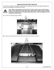
... boards to protect the front bezel and LCD screen from the wall outlet. A 23 www.polaroid.com Note: Before disassembly of any objects into the vent holes in the TV case. (1) Remove 4 screws (A) from the TV. Never insert any part the TV, make sure the power is OFF, and the power cord is removed from being scratched...
... boards to protect the front bezel and LCD screen from the wall outlet. A 23 www.polaroid.com Note: Before disassembly of any objects into the vent holes in the TV case. (1) Remove 4 screws (A) from the TV. Never insert any part the TV, make sure the power is OFF, and the power cord is removed from being scratched...

Service Manual
Page 25
... the TV case. A 25 www.polaroid.com The following LCD panel disassembly/removal instructions may not apply to discharge before removing so the bezel is not damaged. (1) Remove 6 screws (A) from the rear cabinet cover. Allow time for power within all system boards to all models. Never insert any part the TV, make sure the power is...
... the TV case. A 25 www.polaroid.com The following LCD panel disassembly/removal instructions may not apply to discharge before removing so the bezel is not damaged. (1) Remove 6 screws (A) from the rear cabinet cover. Allow time for power within all system boards to all models. Never insert any part the TV, make sure the power is...
Service Manual
Page 32
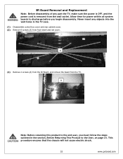
... of any objects into the vent holes in the section, Before Returning This Product to discharge before you must follow the steps outlined in the TV case. (1) Disassemble control box cover and rear cabinet cover. (2) Remove 8 screws (A) from front bezel and net cover. A Note: Before returning this ...and remove the board from the wall outlet. Allow time for power within all system boards to the User, on page 21. Never insert any part the TV, make sure the power is OFF, and the power cord is removed from the TV. This procedure ensures that the chassis will not cause electric ...
... of any objects into the vent holes in the section, Before Returning This Product to discharge before you must follow the steps outlined in the TV case. (1) Disassemble control box cover and rear cabinet cover. (2) Remove 8 screws (A) from front bezel and net cover. A Note: Before returning this ...and remove the board from the wall outlet. Allow time for power within all system boards to the User, on page 21. Never insert any part the TV, make sure the power is OFF, and the power cord is removed from the TV. This procedure ensures that the chassis will not cause electric ...
Service Manual
Page 33
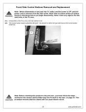
...remove the control button board (A). Never insert any part the TV, make sure the power is OFF, and the power cord is attached with glue. This procedure ensures that the chassis will not cause electric shock. 33 www.polaroid.com Front/Side Control Buttons Removal and Replacement Note: Before ...disassembly of any objects into the vent holes in the section, Before Returning This Product to discharge before you must follow the steps outlined in the TV case. (1) Disassemble control box...
...remove the control button board (A). Never insert any part the TV, make sure the power is OFF, and the power cord is attached with glue. This procedure ensures that the chassis will not cause electric shock. 33 www.polaroid.com Front/Side Control Buttons Removal and Replacement Note: Before ...disassembly of any objects into the vent holes in the section, Before Returning This Product to discharge before you must follow the steps outlined in the TV case. (1) Disassemble control box...
Service Manual
Page 34
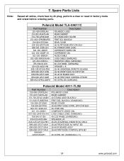
...-FU67G-AH 151-700-GF401XAH 151-A01-GF408BUPS0 154-004-GF32WH POLAROID LOGO REAR CABINET 40 STAND ASSY SILVER FRNT BZL BLK/SILV REAR COVER 154-501-GF370-AH 600-181-3200-LIH 26-42 FRT/SIDE BTN CVR SILV AC POWER CORD (USA) 621-181-2000H 621-181-3020P-1H 621-181... (SAMSUNG) 40 LCD PANEL (SAMSUNG) SPEAKER L-R 845-C45-GF1XA-PEH 899-A00-GF271XAH 26-46 UNIVERSAL REMOTE SILV/BLK 26-46 FRONT/SIDE AV INPUT BD 899-E00-GF271XAH 899-K00-GF271XAH 909-KS2-GF4012XAPH 26-46 IR BOARD ASSY 26-46 FRNT/SIDE CONTROL BTN BD 40 CNTRL BX (SAMSUNG) Polaroid Model 4011-TLXB Part...
...-FU67G-AH 151-700-GF401XAH 151-A01-GF408BUPS0 154-004-GF32WH POLAROID LOGO REAR CABINET 40 STAND ASSY SILVER FRNT BZL BLK/SILV REAR COVER 154-501-GF370-AH 600-181-3200-LIH 26-42 FRT/SIDE BTN CVR SILV AC POWER CORD (USA) 621-181-2000H 621-181-3020P-1H 621-181... (SAMSUNG) 40 LCD PANEL (SAMSUNG) SPEAKER L-R 845-C45-GF1XA-PEH 899-A00-GF271XAH 26-46 UNIVERSAL REMOTE SILV/BLK 26-46 FRONT/SIDE AV INPUT BD 899-E00-GF271XAH 899-K00-GF271XAH 909-KS2-GF4012XAPH 26-46 IR BOARD ASSY 26-46 FRNT/SIDE CONTROL BTN BD 40 CNTRL BX (SAMSUNG) Polaroid Model 4011-TLXB Part...

Service Manual
Page 45
TMDS Data 17. Clock + 11. CEC/GND 18. +5V Power 19. Red Ground 7. H-sync. 14. SCL For DDC1/2B RCA jacks are all female type. TMDS Data 1+ 5. CEC 14. NC 15. Sync. SDA For DDC1/... shield 12. DDC DATA 17. TMDS Data 0+ 8. Vdd from PC 10. Green Ground 8. GND 12. HMDI connector is described as below: 1: Ground 2: Ground 3: Y 4: C 45 www.polaroid.com TMDS Data 010. GND 5. Clock 13. Blue Ground 9. +5V from PC for video/audio mode. 1. TMDS Data 24. Green Video 3. TMDS Data 1 shield 6. GND...
TMDS Data 17. Clock + 11. CEC/GND 18. +5V Power 19. Red Ground 7. H-sync. 14. SCL For DDC1/2B RCA jacks are all female type. TMDS Data 1+ 5. CEC 14. NC 15. Sync. SDA For DDC1/... shield 12. DDC DATA 17. TMDS Data 0+ 8. Vdd from PC 10. Green Ground 8. GND 12. HMDI connector is described as below: 1: Ground 2: Ground 3: Y 4: C 45 www.polaroid.com TMDS Data 010. GND 5. Clock 13. Blue Ground 9. +5V from PC for video/audio mode. 1. TMDS Data 24. Green Video 3. TMDS Data 1 shield 6. GND...

User Guide
Page 4
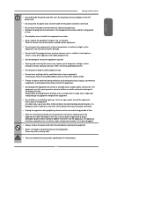
... This symbol is an important feature. To reduce the risk of fire or electric shock, do not expose this equipment from the type of power source indicated on any injuries, the following safety precautions should be performed. ▪ Do not place the equipment on the rear of this manual completely...
... This symbol is an important feature. To reduce the risk of fire or electric shock, do not expose this equipment from the type of power source indicated on any injuries, the following safety precautions should be performed. ▪ Do not place the equipment on the rear of this manual completely...
User Guide
Page 5
... ▪ Do not install the equipment near water. ▪ Never expose the equipment to fire or electric shock. ▪ Protect the power cord from being walked on or pinchrd particularly at plugs ,convenience receptacles, and the point where they exit from the outlet before cleaning the equipment...injury to children or adults and serious damage to rain or moisture, does not operate normally, or has been dropped. ▪ Always remove the power cord from the apparatus. ▪ Do not place the equipment on top. ▪ Do not insert anything into the ventilation holes of the ...
... ▪ Do not install the equipment near water. ▪ Never expose the equipment to fire or electric shock. ▪ Protect the power cord from being walked on or pinchrd particularly at plugs ,convenience receptacles, and the point where they exit from the outlet before cleaning the equipment...injury to children or adults and serious damage to rain or moisture, does not operate normally, or has been dropped. ▪ Always remove the power cord from the apparatus. ▪ Do not place the equipment on top. ▪ Do not insert anything into the ventilation holes of the ...
User Guide
Page 6
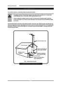
...in wire Ground clamps Electric service equipment Antenna discharge unit (NEC section 810-20) Grounding conductors (NEC section 810-20) Ground clamps Power service grounding (NEC Art250 part H) NEC : National Electrical code EXAMPLE OF OUTDOOR ANTENNA GROUNDING 4 Warnings and Precautions Outdoor Antenna Safety ...9642; An outdoor antenna should not be located in any area where it could come in contact with overhead power lines, or any other electric light or power circuits. ▪ When installing an outdoor antenna system, extreme caution should be taken to prevent contact with ...
...in wire Ground clamps Electric service equipment Antenna discharge unit (NEC section 810-20) Grounding conductors (NEC section 810-20) Ground clamps Power service grounding (NEC Art250 part H) NEC : National Electrical code EXAMPLE OF OUTDOOR ANTENNA GROUNDING 4 Warnings and Precautions Outdoor Antenna Safety ...9642; An outdoor antenna should not be located in any area where it could come in contact with overhead power lines, or any other electric light or power circuits. ▪ When installing an outdoor antenna system, extreme caution should be taken to prevent contact with ...
User Guide
Page 9
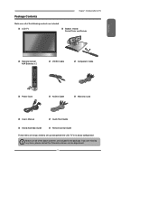
...ENTER Power Cord VIDEO Cable Component Cable AUDIO Cable Warranty Card User's Manual Quick Start Guide Stand Assembly Guide Remote control Guide These items are all you are missing any items, please contact the Polaroid customer service department. 7 If you need to set up and operate the LCD TV ...in the package. Make sure all of the above contents are included in its basic configuration. Package Contents Chapter 1 Introducing the LCD TV Make sure all of ...
...ENTER Power Cord VIDEO Cable Component Cable AUDIO Cable Warranty Card User's Manual Quick Start Guide Stand Assembly Guide Remote control Guide These items are all you are missing any items, please contact the Polaroid customer service department. 7 If you need to set up and operate the LCD TV ...in the package. Make sure all of the above contents are included in its basic configuration. Package Contents Chapter 1 Introducing the LCD TV Make sure all of ...
User Guide
Page 12
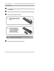
... (+) and ( - ) ends indicated in remote control. terminal (refer to the LCD TV's ANT. Step1 Slide the back cover up to open the battery compartment of the TV and connect the power cord to page19-27). 10 Connect the AC power cord at the back of the remote control. Slide the cover back into... place. Chapter 1 Introducing the LCD TV How to setup the TV Use a supplied antenna cable to connect the ...
... (+) and ( - ) ends indicated in remote control. terminal (refer to the LCD TV's ANT. Step1 Slide the back cover up to open the battery compartment of the TV and connect the power cord to page19-27). 10 Connect the AC power cord at the back of the remote control. Slide the cover back into... place. Chapter 1 Introducing the LCD TV How to setup the TV Use a supplied antenna cable to connect the ...
User Guide
Page 14
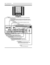
... audio system. AC IN Connects to the AUDIO(L/R) input jacks on AV equipment. AUDIO OUT-STEREO Connects to the AC power cord. 12 Chapter 1 Introducing the LCD TV Rear View and Jacks VIDEO2 IN Connects to the S-VIDEO and AUDIO(L/R) output jacks on external video equipment. S-VIDEO IN ...Connects to the composite VIDEO and AUDIO(L/R) output jacks on external video equipment. HDTV/TV Air/CABLE VHF/UHF IN TV CABLE/AIR Connects RF...
... audio system. AC IN Connects to the AUDIO(L/R) input jacks on AV equipment. AUDIO OUT-STEREO Connects to the AC power cord. 12 Chapter 1 Introducing the LCD TV Rear View and Jacks VIDEO2 IN Connects to the S-VIDEO and AUDIO(L/R) output jacks on external video equipment. S-VIDEO IN ...Connects to the composite VIDEO and AUDIO(L/R) output jacks on external video equipment. HDTV/TV Air/CABLE VHF/UHF IN TV CABLE/AIR Connects RF...

User Guide
Page 17
...The antenna requirements for good color TV reception are completed. When connecting any external equipment, do not connect any external equipment to be attached to a terminal without tools. The following is a brief explanation of the type of any AC power cords to a 75-ohm terminal... can be attached to wall outlets until all other connections are more important than those for a black & white TV reception. ENGLISH Chapter 2 Installing the LCD TV Chapter 2 Installing the LCD TV Refer to the owner's manual of connection that is provided with the various antenna systems. ■ A 75...
...The antenna requirements for good color TV reception are completed. When connecting any external equipment, do not connect any external equipment to be attached to a terminal without tools. The following is a brief explanation of the type of any AC power cords to a 75-ohm terminal... can be attached to wall outlets until all other connections are more important than those for a black & white TV reception. ENGLISH Chapter 2 Installing the LCD TV Chapter 2 Installing the LCD TV Refer to the owner's manual of connection that is provided with the various antenna systems. ■ A 75...

User Guide
Page 20
...it does not disconnect the device from the socket. 18 The POWER button on the LCD TV. Firm Plastic Prying Tool (Using a metal tool may cause shock) Back of the TV and connect the power cord to protect your TV has no power, check the fuse by prying the cover off, following the ...5x20mm Time Lag Fuse (Slow Blow) to the LCD TV's TV CABLE terminal. Chapter 2 Installing the LCD TV Use a supplied antenna cable to connect the TV signal to replace the fuse. HDTV/TV Air/CABLE VHF/UHF IN Connect the AC power cord at the back of TV 4A 250V 5x20mm Fuse BE SURE TO UNPLUG AC...
...it does not disconnect the device from the socket. 18 The POWER button on the LCD TV. Firm Plastic Prying Tool (Using a metal tool may cause shock) Back of the TV and connect the power cord to protect your TV has no power, check the fuse by prying the cover off, following the ...5x20mm Time Lag Fuse (Slow Blow) to the LCD TV's TV CABLE terminal. Chapter 2 Installing the LCD TV Use a supplied antenna cable to connect the TV signal to replace the fuse. HDTV/TV Air/CABLE VHF/UHF IN Connect the AC power cord at the back of TV 4A 250V 5x20mm Fuse BE SURE TO UNPLUG AC...


