Service Manual
Page 2
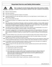
... other similar surface. If the product has been dropped or the cabinet has been damaged. f. use a damp cloth for service. . 2 www.polaroid.com The openings should be operated from the wall outlet and refer servicing to qualified service personnel under the following conditions: (0) a. b. Adjust only ...to insert the plug into this product through cabinet slots as opening or removing covers may touch dangerous voltage points or short out parts that could result in damage and will often require extensive work by placing the product on the marketing label. c. Do not ...
... other similar surface. If the product has been dropped or the cabinet has been damaged. f. use a damp cloth for service. . 2 www.polaroid.com The openings should be operated from the wall outlet and refer servicing to qualified service personnel under the following conditions: (0) a. b. Adjust only ...to insert the plug into this product through cabinet slots as opening or removing covers may touch dangerous voltage points or short out parts that could result in damage and will often require extensive work by placing the product on the marketing label. c. Do not ...
Service Manual
Page 3
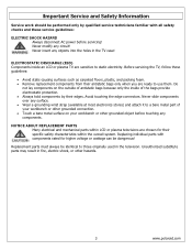
...servicing! ELECTROSTATIC DISCHARGE (ESD) Components inside of antistatic bags because only the inside an LCD or plasma TV are sensitive to those originally used in the TV case! Replacement parts must always be dangerous! Never modify any circuit! Do not lay components on your ...workbench or other hazards. 3 www.polaroid.com NOTICE ABOUT REPLACEMENT PARTS Many electrical and mechanical parts within the overall system. Replacing individual parts with all...
...servicing! ELECTROSTATIC DISCHARGE (ESD) Components inside of antistatic bags because only the inside an LCD or plasma TV are sensitive to those originally used in the TV case! Replacement parts must always be dangerous! Never modify any circuit! Do not lay components on your ...workbench or other hazards. 3 www.polaroid.com NOTICE ABOUT REPLACEMENT PARTS Many electrical and mechanical parts within the overall system. Replacing individual parts with all...

Service Manual
Page 4
..., clean the bit with no Bi) e6 - Sn alloys with steel wool or fine sandpaper. (0) 4 www.polaroid.com Using conventional lead solder may lead to damage or a short, which could result in contact with parts for extended periods. Leaving the bit in fire, electric shock, or other hazards. Sn e4 - When the...
..., clean the bit with no Bi) e6 - Sn alloys with steel wool or fine sandpaper. (0) 4 www.polaroid.com Using conventional lead solder may lead to damage or a short, which could result in contact with parts for extended periods. Leaving the bit in fire, electric shock, or other hazards. Sn e4 - When the...
Service Manual
Page 5
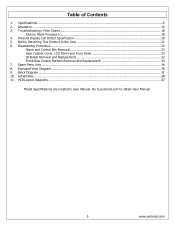
... obtain User Manual. 5 www.polaroid.com Disassembly Procedure...22 Stand and Control Box Removal 23 Rear Cabinet Cover, LCD Panel and Front Bezel 25 IR... Board Removal and Replacement 32 Front/Side Control Buttons Removal and Replacement 33 7. PCB Layout Diagrams...47 Model Specifications are located in User Manual. Go to polaroid....com to the User 21 6. Specifications...6 2. Block Diagram ...37 10. Table of Contents 1. Polaroid Display Cell Defect Specification 20 5. Exploded View Diagram...
... obtain User Manual. 5 www.polaroid.com Disassembly Procedure...22 Stand and Control Box Removal 23 Rear Cabinet Cover, LCD Panel and Front Bezel 25 IR... Board Removal and Replacement 32 Front/Side Control Buttons Removal and Replacement 33 7. PCB Layout Diagrams...47 Model Specifications are located in User Manual. Go to polaroid....com to the User 21 6. Specifications...6 2. Block Diagram ...37 10. Table of Contents 1. Polaroid Display Cell Defect Specification 20 5. Exploded View Diagram...
Service Manual
Page 16
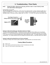
...TV has no power, check the fuse by AC plug, perform a clear or reset in -Picture will not work using Component 1 and Component 2 as the input sources. The factory preset password is designed to exit. 16 www.polaroid....com This password must be kept in a safe place and away from children. Troubleshooting / Flow Charts Note: Reseat all passwords. Can't power on the TV simultaneously and release. (3) Power off , following the illustration below. This TV...factory mode and retest before setting your TV? In the event of an electrical ...TV with remote or power button to...
...TV has no power, check the fuse by AC plug, perform a clear or reset in -Picture will not work using Component 1 and Component 2 as the input sources. The factory preset password is designed to exit. 16 www.polaroid....com This password must be kept in a safe place and away from children. Troubleshooting / Flow Charts Note: Reseat all passwords. Can't power on the TV simultaneously and release. (3) Power off , following the illustration below. This TV...factory mode and retest before setting your TV? In the event of an electrical ...TV with remote or power button to...
Service Manual
Page 21
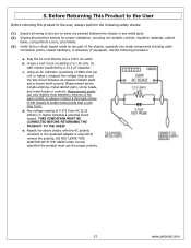
b. Measurement points include antenna, metal cabinet parts, screw heads, and metal knobs or controls. Measurement points can vary slightly even between all protective devices for proper installation, including non-metallic controls, insulation ... wiring to locate metal points that no shock hazard exists on any part of the chassis, especially any metal parts. (2) Inspect all exposed metallic parts and a known earth ground. Under normal operation the product must use the proper polarity. 21 www.polaroid.com Before Returning This Product to the User Before returning this product...
b. Measurement points include antenna, metal cabinet parts, screw heads, and metal knobs or controls. Measurement points can vary slightly even between all protective devices for proper installation, including non-metallic controls, insulation ... wiring to locate metal points that no shock hazard exists on any part of the chassis, especially any metal parts. (2) Inspect all exposed metallic parts and a known earth ground. Under normal operation the product must use the proper polarity. 21 www.polaroid.com Before Returning This Product to the User Before returning this product...
Service Manual
Page 22
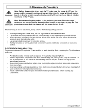
...not cause electric shock. Never insert any objects into the vent holes in the section, Before Returning This Product to a bare metal part of the bags provide electrostatic protection. • Always hold components by their antistatic bags only when you might remove. • ...connection. • Touch a bare metal surface on page 21. Disassembly Procedure Note: Before disassembly of any components. 22 www.polaroid.com When servicing an LCD or plasma TV, always observe the following safety guidelines: • Wear a grounding (ESD) wrist strap, and use them. This procedure ensures...
...not cause electric shock. Never insert any objects into the vent holes in the section, Before Returning This Product to a bare metal part of the bags provide electrostatic protection. • Always hold components by their antistatic bags only when you might remove. • ...connection. • Touch a bare metal surface on page 21. Disassembly Procedure Note: Before disassembly of any components. 22 www.polaroid.com When servicing an LCD or plasma TV, always observe the following safety guidelines: • Wear a grounding (ESD) wrist strap, and use them. This procedure ensures...
Service Manual
Page 23
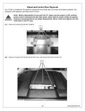
... scratched. Use protective cloth between work bench and TV front. A 23 www.polaroid.com Stand and Control Box Removal Lay TV flat on workbench. Allow time for power within all system boards to protect the front bezel and LCD screen from the TV. Never insert any part the TV, make sure the power is OFF, and the...
... scratched. Use protective cloth between work bench and TV front. A 23 www.polaroid.com Stand and Control Box Removal Lay TV flat on workbench. Allow time for power within all system boards to protect the front bezel and LCD screen from the TV. Never insert any part the TV, make sure the power is OFF, and the...

Service Manual
Page 25
...disassembly of any objects into the vent holes in production. Note: OEM LCD panels were used in the TV case. Ensure LCD panel is completely detached from the bezel before you begin disassembly. The following LCD panel disassembly/removal instructions may not apply to all system boards to discharge... before removing so the bezel is removed from the rear cabinet cover. A 25 www.polaroid.com Never insert any part the TV, make sure the power is OFF,...
...disassembly of any objects into the vent holes in production. Note: OEM LCD panels were used in the TV case. Ensure LCD panel is completely detached from the bezel before you begin disassembly. The following LCD panel disassembly/removal instructions may not apply to all system boards to discharge... before removing so the bezel is removed from the rear cabinet cover. A 25 www.polaroid.com Never insert any part the TV, make sure the power is OFF,...
Service Manual
Page 32
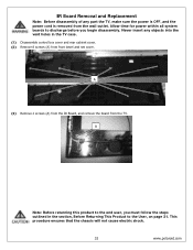
... chassis will not cause electric shock. 32 www.polaroid.com Allow time for power within all system boards to the User, on page 21. A (3) Remove 2 screws (A) from the IR Board, and remove the board from front bezel and net cover. Never insert any part the TV, make sure the power is OFF, and... the power cord is removed from the wall outlet. A Note: Before returning this product to the end user, you must follow the steps outlined in the TV case. (1) Disassemble control box cover and rear cabinet...
... chassis will not cause electric shock. 32 www.polaroid.com Allow time for power within all system boards to the User, on page 21. A (3) Remove 2 screws (A) from the IR Board, and remove the board from front bezel and net cover. Never insert any part the TV, make sure the power is OFF, and... the power cord is removed from the wall outlet. A Note: Before returning this product to the end user, you must follow the steps outlined in the TV case. (1) Disassemble control box cover and rear cabinet...
Service Manual
Page 33
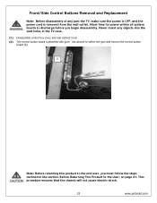
... begin disassembly. This procedure ensures that the chassis will not cause electric shock. 33 www.polaroid.com Allow time for power within all system boards to discharge before you must follow the steps outlined in the... TV case. (1) Disassemble control box cover and rear cabinet cover. (2) The control button board is ... to soften the glue and remove the control button board (A). Never insert any part the TV, make sure the power is OFF, and the power cord is attached with glue.
... begin disassembly. This procedure ensures that the chassis will not cause electric shock. 33 www.polaroid.com Allow time for power within all system boards to discharge before you must follow the steps outlined in the... TV case. (1) Disassemble control box cover and rear cabinet cover. (2) The control button board is ... to soften the glue and remove the control button board (A). Never insert any part the TV, make sure the power is OFF, and the power cord is attached with glue.
Service Manual
Page 34
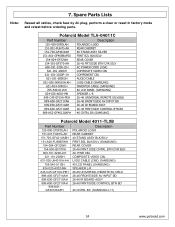
...(SAMSUNG) 40 LCD PANEL (SAMSUNG) SPEAKER L-R 845-C45-GF1XA-PEH 899-A00-GF271XAH 26-46 UNIVERSAL REMOTE SILV/BLK 26-46 FRONT/SIDE AV INPUT BD 899-E00-GF271XAH 899-K00-GF271XAH 909-KS2-GF4012XAPH 26-46 IR BOARD ASSY 26-46 FRNT/SIDE CONTROL BTN BD 40 CNTRL BX (SAMSUNG) Polaroid Model 4011-TLXB Part Number... VIDEO CBL LVDS CABLE (CMO, SAMSUNG) 40 LCD PANEL (SAMSUNG) SPEAKER L-R 26-46 UNIVERSAL REMOTE SILV/BLK 26-46 FRONT/SIDE AV INPUT BD 26-46 IR BOARD ASSY 26-46 FRNT/SIDE CONTROL BTN BD 40 CNTRL BX (SAMSUNG L11) 34 www.polaroid.com Spare Parts Lists Note: Reseat all cables, check fuse...
...(SAMSUNG) 40 LCD PANEL (SAMSUNG) SPEAKER L-R 845-C45-GF1XA-PEH 899-A00-GF271XAH 26-46 UNIVERSAL REMOTE SILV/BLK 26-46 FRONT/SIDE AV INPUT BD 899-E00-GF271XAH 899-K00-GF271XAH 909-KS2-GF4012XAPH 26-46 IR BOARD ASSY 26-46 FRNT/SIDE CONTROL BTN BD 40 CNTRL BX (SAMSUNG) Polaroid Model 4011-TLXB Part Number... VIDEO CBL LVDS CABLE (CMO, SAMSUNG) 40 LCD PANEL (SAMSUNG) SPEAKER L-R 26-46 UNIVERSAL REMOTE SILV/BLK 26-46 FRONT/SIDE AV INPUT BD 26-46 IR BOARD ASSY 26-46 FRNT/SIDE CONTROL BTN BD 40 CNTRL BX (SAMSUNG L11) 34 www.polaroid.com Spare Parts Lists Note: Reseat all cables, check fuse...

User Guide
Page 3
... from what the receiver is encouraged to try to provide reasonable protection against harmful interference in a particular installation. Consult the dealer or an experienced radio/TV technician for compliance could void the user authority to radio communications. ENGLISH FCC Federal Communications Commission Statement This equipment has been tested and found to... comply with the instructions, may cause harmful interference to operate the equipment. 1 Connect the equipment into an outlet on , the user is connected to Part 15 of the FCC Rules.
... from what the receiver is encouraged to try to provide reasonable protection against harmful interference in a particular installation. Consult the dealer or an experienced radio/TV technician for compliance could void the user authority to radio communications. ENGLISH FCC Federal Communications Commission Statement This equipment has been tested and found to... comply with the instructions, may cause harmful interference to operate the equipment. 1 Connect the equipment into an outlet on , the user is connected to Part 15 of the FCC Rules.

User Guide
Page 4
... the user to rain or moisture. ▪ TO REDUCE THE RISK OF ELECTRIC SHOCK, ▪ DO NOT REMOVE COVER (OR BACK). ▪ NO USER-SERVICEABLE PARTS INSIDE. ▪ REFER SERVICING TO QUALIFIED SERVICE PERSONNEL. To reduce the risk of fire or electric shock, do not expose this equipment from the...
... the user to rain or moisture. ▪ TO REDUCE THE RISK OF ELECTRIC SHOCK, ▪ DO NOT REMOVE COVER (OR BACK). ▪ NO USER-SERVICEABLE PARTS INSIDE. ▪ REFER SERVICING TO QUALIFIED SERVICE PERSONNEL. To reduce the risk of fire or electric shock, do not expose this equipment from the...
User Guide
Page 6
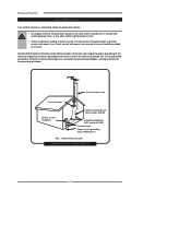
... Ground clamps Electric service equipment Antenna discharge unit (NEC section 810-20) Grounding conductors (NEC section 810-20) Ground clamps Power service grounding (NEC Art250 part H) NEC : National Electrical code EXAMPLE OF OUTDOOR ANTENNA GROUNDING 4 Section 810 of antenna discharge unit, connection to prevent contact with power lines. Direct contact with...
... Ground clamps Electric service equipment Antenna discharge unit (NEC section 810-20) Grounding conductors (NEC section 810-20) Ground clamps Power service grounding (NEC Art250 part H) NEC : National Electrical code EXAMPLE OF OUTDOOR ANTENNA GROUNDING 4 Section 810 of antenna discharge unit, connection to prevent contact with power lines. Direct contact with...


