Owner's Manual
Page 2
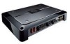
... have any other information. Box 1760 Long Beach, CA 90801-1760 800-421-1404 7 CANADA Pioneer Electronics of enjoyment. After-sales service for Pioneer products Please contact the dealer or distributor from where you purchased the product for purchasing this manual.... Contents Before Using This Product Before Using This Product 1 After-sales service for Pioneer products 1 Information to User 2 Important 2 Visit our website 2 About This Product 2 CAUTION 2 WARNING 2 Setting the Unit 3 Power Indicator 3 Top Cover 3 Subsonic Select Switch 3 Bass Boost Control 3 BFC (Beat ...
... have any other information. Box 1760 Long Beach, CA 90801-1760 800-421-1404 7 CANADA Pioneer Electronics of enjoyment. After-sales service for Pioneer products Please contact the dealer or distributor from where you purchased the product for purchasing this manual.... Contents Before Using This Product Before Using This Product 1 After-sales service for Pioneer products 1 Information to User 2 Important 2 Visit our website 2 About This Product 2 CAUTION 2 WARNING 2 Setting the Unit 3 Power Indicator 3 Top Cover 3 Subsonic Select Switch 3 Bass Boost Control 3 BFC (Beat ...

Owner's Manual
Page 3
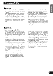
...wrench can still hear normal traffic sound. • Check the connections of the power supply and speakers if the fuse of any attached speakers could result from damage. • DO NOT allow amplifier to protect all cables and important equipment such as loss or theft. 2 Receive ...'s manuals, order product catalogues, research new products, and much more. In such a case, switch the power to the touch and minor burns could result. 2 In addition, the amplifier surface and the surface of the separately sold separately. Keep the card handy for installation of this information in...
...wrench can still hear normal traffic sound. • Check the connections of the power supply and speakers if the fuse of any attached speakers could result from damage. • DO NOT allow amplifier to protect all cables and important equipment such as loss or theft. 2 Receive ...'s manuals, order product catalogues, research new products, and much more. In such a case, switch the power to the touch and minor burns could result. 2 In addition, the amplifier surface and the surface of the separately sold separately. Keep the card handy for installation of this information in...

Owner's Manual
Page 4
... subsonic filter cuts inaudible frequencies below 20 Hz to the amplifier, see the "Connection Diagram" section. 3 BFC (Beat Frequency Control) Switch BFC switch is switched on the bottom of connecting the bass boost remote control to eliminate unwanted vibrations and minimize power loss. Top Cover Before setting up the unit, unfasten the... boost level from 0, 6, 9 and 12 dB. If you hear a beat while listening to an AM broadcast with a 4 mm hexagonal wrench and remove the top cover. Power Indicator The power indicator lights when the...
... subsonic filter cuts inaudible frequencies below 20 Hz to the amplifier, see the "Connection Diagram" section. 3 BFC (Beat Frequency Control) Switch BFC switch is switched on the bottom of connecting the bass boost remote control to eliminate unwanted vibrations and minimize power loss. Top Cover Before setting up the unit, unfasten the... boost level from 0, 6, 9 and 12 dB. If you hear a beat while listening to an AM broadcast with a 4 mm hexagonal wrench and remove the top cover. Power Indicator The power indicator lights when the...
Owner's Manual
Page 5
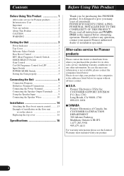
... when the volume is too low, even when the volume of multiple amplifiers. For connection instructions, see the "Using the Speaker Input" section. If the speaker impedance exceeds 2 Ω (4 Ω when using with an RCA equipped Pioneer car stereo with synthetic impeadance 2 Ω to 8 Ω, slide...level to use of the car stereo used when using speakers with RCA pin cord. In this power amplifier is necessary to match the car stereo output level. • If you can select amplifier's sync mode from MASTER, SYNC and SYNC INV. See the "Connecting the Speaker Wires" section...
... when the volume is too low, even when the volume of multiple amplifiers. For connection instructions, see the "Using the Speaker Input" section. If the speaker impedance exceeds 2 Ω (4 Ω when using with an RCA equipped Pioneer car stereo with synthetic impeadance 2 Ω to 8 Ω, slide...level to use of the car stereo used when using speakers with RCA pin cord. In this power amplifier is necessary to match the car stereo output level. • If you can select amplifier's sync mode from MASTER, SYNC and SYNC INV. See the "Connecting the Speaker Wires" section...
Owner's Manual
Page 6
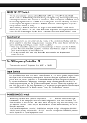
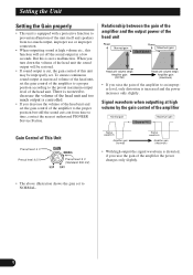
Relationship between the gain of the amplifier and the output power of the head unit Power Normal gain Power Maximum gain Equal power Head unit volume steps Amplifier gain (normal) Head unit volume steps Amplifier gain (maximum) • If you raise the gain of the amplifier to an improper level, only distortion is distorted, if you raise the gain... • This unit is equipped with a protective function to prevent malfunction of the unit itself and speakers from time to time, contact the nearest authorized PIONEER Service Station.
Relationship between the gain of the amplifier and the output power of the head unit Power Normal gain Power Maximum gain Equal power Head unit volume steps Amplifier gain (normal) Head unit volume steps Amplifier gain (maximum) • If you raise the gain of the amplifier to an improper level, only distortion is distorted, if you raise the gain... • This unit is equipped with a protective function to prevent malfunction of the unit itself and speakers from time to time, contact the nearest authorized PIONEER Service Station.
Owner's Manual
Page 7
... the speaker wires. Before installing it should. • Never feed power to other equipment by cutting the insulation of the power supply wire to tap from the antenna, antenna cable and tuner. 6 Amplifier damage, smoke, and overheating could result. • Connect either of... three subwoofers to the amplifier; 1: a subwoofer with a 420 W or larger nominal input and an impedance 4 Ω...
... the speaker wires. Before installing it should. • Never feed power to other equipment by cutting the insulation of the power supply wire to tap from the antenna, antenna cable and tuner. 6 Amplifier damage, smoke, and overheating could result. • Connect either of... three subwoofers to the amplifier; 1: a subwoofer with a 420 W or larger nominal input and an impedance 4 Ω...
Owner's Manual
Page 8
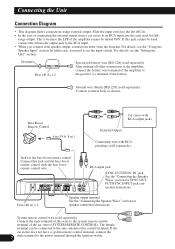
...this jack and the bass boost remote control with RCA pin plugs (sold separately) After making all other connections at the amplifier, connect the battery wire terminal of the amplifier to set the input switch. In either case, you connect with speaker output, connections defer from a car stereo to...used , connect the subwoofer output jack to the RCA input. • When you need to the positive (+) terminal of the amplifier cannot be connected to the power terminal through the ignition switch. RCA input jack SYNC OUT/SYNC IN jack See the "Connecting the Speaker Wires" section for ...
...this jack and the bass boost remote control with RCA pin plugs (sold separately) After making all other connections at the amplifier, connect the battery wire terminal of the amplifier to set the input switch. In either case, you connect with speaker output, connections defer from a car stereo to...used , connect the subwoofer output jack to the RCA input. • When you need to the positive (+) terminal of the amplifier cannot be connected to the power terminal through the ignition switch. RCA input jack SYNC OUT/SYNC IN jack See the "Connecting the Speaker Wires" section for ...
Owner's Manual
Page 9
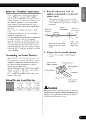
...8226; Do not solder or bind the ends of the twisted wires. • Fasten while making all other connections to the amplifier, connect the battery wire terminal of the battery. Pass the battery wire from the engine compartment to the interior of the vehicle... will become loose over time, it must be periodically inspected and tightened as follows. Positive (+) terminal Engine compartment Interior of this amplifier (Power terminal, GND terminal, System remote control terminal). ENGLISH ESPAÑOL DEUTSCH FRANÇAIS ITALIANO NEDERLANDS Solderless Terminal Connections •...
...8226; Do not solder or bind the ends of the twisted wires. • Fasten while making all other connections to the amplifier, connect the battery wire terminal of the battery. Pass the battery wire from the engine compartment to the interior of the vehicle... will become loose over time, it must be periodically inspected and tightened as follows. Positive (+) terminal Engine compartment Interior of this amplifier (Power terminal, GND terminal, System remote control terminal). ENGLISH ESPAÑOL DEUTSCH FRANÇAIS ITALIANO NEDERLANDS Solderless Terminal Connections •...

Owner's Manual
Page 10
... the input switch to the right (SP). • As a result of connecting the car stereo speaker output wire to the amplifier, the power of the amplifier is turned on when the car stereo is not necessary to 12 mm (1/2 inch). Using the Speaker Input Connect the car stereo...2. Note: • Connect the system remote control wire when the power of the amplifiers with the system remote control wire. Connections when using a speaker input wire with RCA pin cord, the amplifier power is only turned on when one amplifier is turned on . 9 Connecting the Unit Connecting the Speaker Output ...
... the input switch to the right (SP). • As a result of connecting the car stereo speaker output wire to the amplifier, the power of the amplifier is turned on when the car stereo is not necessary to 12 mm (1/2 inch). Using the Speaker Input Connect the car stereo...2. Note: • Connect the system remote control wire when the power of the amplifiers with the system remote control wire. Connections when using a speaker input wire with RCA pin cord, the amplifier power is only turned on when one amplifier is turned on . 9 Connecting the Unit Connecting the Speaker Output ...

Owner's Manual
Page 11
...; (or lower) in parallel to achieve a 1 Ω (or lower) bridged mode (Diagram B). be in MASTER position. These settings are inactive when set on an amplifier set the POWER MODE switch to the HI-CURRENT position. Improper 4 Ω Speaker 4 Ω Speaker 2 Ω Speaker 2 Ω Speaker 2 Ω Bridged Mode 1 Ω Bridged Mode Do NOT...
...; (or lower) in parallel to achieve a 1 Ω (or lower) bridged mode (Diagram B). be in MASTER position. These settings are inactive when set on an amplifier set the POWER MODE switch to the HI-CURRENT position. Improper 4 Ω Speaker 4 Ω Speaker 2 Ω Speaker 2 Ω Speaker 2 Ω Bridged Mode 1 Ω Bridged Mode Do NOT...
Owner's Manual
Page 12
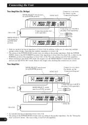
...according to 8 Ω MODE SELECT switch must be in SYNC position. See the "Setting the Unit" section for both amplifiers. • When switching to 16 Ω. Slide the POWER MODE switch to the HI-CURRENT position if the impedance is from 2 Ω to less than 4 Ω, or ...and you can find SYNC INV switch. Connecting speaker wire (sold separately). In addition, in MASTER position. Two Amplifier MODE SELECT switch must be in the case of the POWER MODE switch varies according to 16 Ω MODE SELECT switch must be in MASTER position. For details, see...
...according to 8 Ω MODE SELECT switch must be in SYNC position. See the "Setting the Unit" section for both amplifiers. • When switching to 16 Ω. Slide the POWER MODE switch to the HI-CURRENT position if the impedance is from 2 Ω to less than 4 Ω, or ...and you can find SYNC INV switch. Connecting speaker wire (sold separately). In addition, in MASTER position. Two Amplifier MODE SELECT switch must be in the case of the POWER MODE switch varies according to 16 Ω MODE SELECT switch must be in MASTER position. For details, see...
Owner's Manual
Page 13
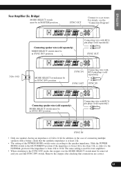
...switch must be in SYNC INV position. SYNC IN Connecting wire with RCA pin plugs (sold separately). The same setting is used for four amplifiers. • When switching to 16 Ω MODE SELECT switch must be removed and you can find SYNC INV switch. SYNC OUT Connect...(sold separately). Connecting wire with a bridge, check that connections are correct. 12 SYNC IN • Only use speakers having an impedance of the POWER MODE switch varies according to 16 Ω. Remove the stopper after checking that the synthetic impedance is from 2 Ω to less than 4 Ω...
...switch must be in SYNC INV position. SYNC IN Connecting wire with RCA pin plugs (sold separately). The same setting is used for four amplifiers. • When switching to 16 Ω MODE SELECT switch must be removed and you can find SYNC INV switch. SYNC OUT Connect...(sold separately). Connecting wire with a bridge, check that connections are correct. 12 SYNC IN • Only use speakers having an impedance of the POWER MODE switch varies according to 16 Ω. Remove the stopper after checking that the synthetic impedance is from 2 Ω to less than 4 Ω...
Owner's Manual
Page 14
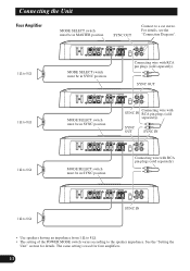
...OUT SYNC IN MODE SELECT switch must be in SYNC position. Connecting wire with RCA pin plugs (sold separately). Connecting the Unit Four Amplifier MODE SELECT switch must be in SYNC position. SYNC OUT MODE SELECT switch must be in MASTER position. The same setting is used... for details. See the "Setting the Unit" section for four amplifiers. 13 Connecting wire with RCA pin plugs (sold separately). 1 Ω to 8 Ω SYNC IN • Use speakers having an impedance from 1 Ω ...
...OUT SYNC IN MODE SELECT switch must be in SYNC position. Connecting wire with RCA pin plugs (sold separately). Connecting the Unit Four Amplifier MODE SELECT switch must be in SYNC position. SYNC OUT MODE SELECT switch must be in MASTER position. The same setting is used... for details. See the "Setting the Unit" section for four amplifiers. 13 Connecting wire with RCA pin plugs (sold separately). 1 Ω to 8 Ω SYNC IN • Use speakers having an impedance from 1 Ω ...

Owner's Manual
Page 17
...: 50 Hz Level: 0 / 6 / 9 / 12 dB Gain control ...RCA: 400 mV to 6.5 V SP: 1.6 V to 26 V Maximum input level / impedance ...RCA: 6.5 V / 22 kΩ SP: 26 V / 90 kΩ Power output NORMAL mode: 400 W RMS × 1 channel (at 4 Ω and 1% THD+N) 600 W RMS × 1 channel (at 100 Hz , 2 Ω and 1% THD+N) HI-CURRENT mode: 150... input. Use this value when working out total current drawn by this unit when an audio signal is nearly the maximum current drawn by multiple power amplifiers. 16
...: 50 Hz Level: 0 / 6 / 9 / 12 dB Gain control ...RCA: 400 mV to 6.5 V SP: 1.6 V to 26 V Maximum input level / impedance ...RCA: 6.5 V / 22 kΩ SP: 26 V / 90 kΩ Power output NORMAL mode: 400 W RMS × 1 channel (at 4 Ω and 1% THD+N) 600 W RMS × 1 channel (at 100 Hz , 2 Ω and 1% THD+N) HI-CURRENT mode: 150... input. Use this value when working out total current drawn by this unit when an audio signal is nearly the maximum current drawn by multiple power amplifiers. 16

