Owner's Manual
Page 2
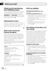
... with this unit for after-sales service (including warranty conditions) or any other information. Once you have established a comfortable sound level, set the dial and leave it at a safe level-a level that you read...user's right to your unit to this PIONEER product. Please keep the details of your purchase on the latest products and technologies. 3 Download owner's manuals, order product catalogues, research new products, and much more. Sound can hear it comfortably and clearly, without affecting your hearing "comfort level" adapts to higher volumes of sound, so what sounds...
... with this unit for after-sales service (including warranty conditions) or any other information. Once you have established a comfortable sound level, set the dial and leave it at a safe level-a level that you read...user's right to your unit to this PIONEER product. Please keep the details of your purchase on the latest products and technologies. 3 Download owner's manuals, order product catalogues, research new products, and much more. Sound can hear it comfortably and clearly, without affecting your hearing "comfort level" adapts to higher volumes of sound, so what sounds...
Owner's Manual
Page 3
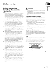
... ! About the Protection function The Protection function will turn off and check the power supply and speaker connections. If the speaker output terminal and speaker wire is applied to the car body. ! Important (Serial number) The serial number is turned on, the power indicator will operate in your vehicle, refer to come into contact with a 12 V battery and negative grounding. En 3 Connect the battery wire directly to the car battery positive terminal + and the ground wire to the speaker out- Do...
... ! About the Protection function The Protection function will turn off and check the power supply and speaker connections. If the speaker output terminal and speaker wire is applied to the car body. ! Important (Serial number) The serial number is turned on, the power indicator will operate in your vehicle, refer to come into contact with a 12 V battery and negative grounding. En 3 Connect the battery wire directly to the car battery positive terminal + and the ground wire to the speaker out- Do...
Owner's Manual
Page 4
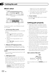
...when using the speaker input terminals, turn these controls to lower level. To adjust the switch, use with an RCA equipped Pioneer car stereo, with an RCA equipped car stereo (standard output of 500 mV), set amplifier gain control to a level appropriate for a few seconds as a normal function, but output is restored when the volume of the head unit is turned up, turn the gain control to higher level. 5 Power indicator The power indicator lights up , turn controls to higher level. ! When the Subwoofer is connected: Select OFF. For use a flathead screwdriver if needed. 1 LPF (low...
...when using the speaker input terminals, turn these controls to lower level. To adjust the switch, use with an RCA equipped Pioneer car stereo, with an RCA equipped car stereo (standard output of 500 mV), set amplifier gain control to a level appropriate for a few seconds as a normal function, but output is restored when the volume of the head unit is turned up, turn the gain control to higher level. 5 Power indicator The power indicator lights up , turn controls to higher level. ! When the Subwoofer is connected: Select OFF. For use a flathead screwdriver if needed. 1 LPF (low...
Owner's Manual
Page 5
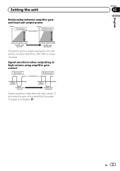
English Section 02 En 5 Signal waveform when outputting at high volume using amplifier gain control Signal waveform distorted with little increase in power. Setting the unit Relationship between amplifier gain and head unit output power If amplifier gain is raised improperly, this will simply increase distortion, with high output, if you raise the gain of the amplifier the power changes only slightly.
English Section 02 En 5 Signal waveform when outputting at high volume using amplifier gain control Signal waveform distorted with little increase in power. Setting the unit Relationship between amplifier gain and head unit output power If amplifier gain is raised improperly, this will simply increase distortion, with high output, if you raise the gain of the amplifier the power changes only slightly.
Owner's Manual
Page 6
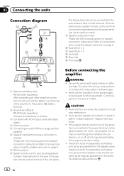
... other amplifier connections, finally connect the battery wire terminal of the car stereo. sive tape. Before connecting the amplifier WARNING ! CAUTION ! If the car stereo lacks a system remote control terminal, connect the male terminal to the system remote control terminal of the amplifier to the positive (+) battery terminal. 2 Ground wire (Black) RD-223 (sold separately) Connect to the power terminal via the ignition switch. 9 Speaker output terminals Please see the following section for speaker connection instructions. Section 03 Connecting the units Connection diagram...
... other amplifier connections, finally connect the battery wire terminal of the car stereo. sive tape. Before connecting the amplifier WARNING ! CAUTION ! If the car stereo lacks a system remote control terminal, connect the male terminal to the system remote control terminal of the amplifier to the positive (+) battery terminal. 2 Ground wire (Black) RD-223 (sold separately) Connect to the power terminal via the ignition switch. 9 Speaker output terminals Please see the following section for speaker connection instructions. Section 03 Connecting the units Connection diagram...
Owner's Manual
Page 7
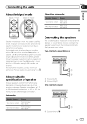
...+ and Right * (Diagram A) or use a single 4 W speaker. About suitable specification of speaker Ensure speakers conform to the figures shown below. Connect the speaker leads to suit the mode according to the following standards, otherwise there is max. 4 W, please carefully check. Two-channel output (Stereo) 1 2 1 Speaker (Left) 2 Speaker (Right) One-channel output 1 1 Speaker (Mono) En 7 For other bridge connection. Connecting the units About bridged mode Other than subwoofer Speaker channel Two-channel output One-channel output Power MAX input: Min. 250 W MAX input: Min. 800...
...+ and Right * (Diagram A) or use a single 4 W speaker. About suitable specification of speaker Ensure speakers conform to the figures shown below. Connect the speaker leads to suit the mode according to the following standards, otherwise there is max. 4 W, please carefully check. Two-channel output (Stereo) 1 2 1 Speaker (Left) 2 Speaker (Right) One-channel output 1 1 Speaker (Mono) En 7 For other bridge connection. Connecting the units About bridged mode Other than subwoofer Speaker channel Two-channel output One-channel output Power MAX input: Min. 250 W MAX input: Min. 800...

Owner's Manual
Page 8
... connections, finally connect the battery wire terminal 1 Lug (sold separately) 2 Battery wire 3 Ground wire 4 Connect the wires to wire ends. Twist Connecting the power terminal The use of a special red battery and ground wire RD-223, available separately, is not securely fixed to the vehicle interior. Section 03 Connecting the units Connections when using the speaker input wire Connect the car stereo speaker output wires to wires. Use pliers, etc., to crimp lugs to the amplifier using the supplied speaker input wire. ! Do not connect both the RCA input and the speaker input...
... connections, finally connect the battery wire terminal 1 Lug (sold separately) 2 Battery wire 3 Ground wire 4 Connect the wires to wire ends. Twist Connecting the power terminal The use of a special red battery and ground wire RD-223, available separately, is not securely fixed to the vehicle interior. Section 03 Connecting the units Connections when using the speaker input wire Connect the car stereo speaker output wires to wires. Use pliers, etc., to crimp lugs to the amplifier using the supplied speaker input wire. ! Do not connect both the RCA input and the speaker input...
Owner's Manual
Page 9
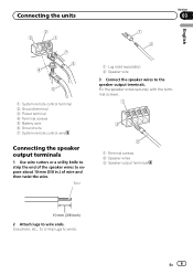
...etc., to crimp lugs to wire ends. En 9 Fix the speaker wires securely with the terminal screws. 1 Terminal screws 2 Speaker wires 3 Speaker output terminals 2 Attach lugs to wires. Twist 1 Lug (sold separately) 2 Speaker wire 3 Connect the speaker wires to expose about 10 mm (3/8 in.) of wire and then twist the wire. Connecting the units Section 03 English 1 System remote control terminal 2 Ground terminal 3 Power terminal 4 Terminal screws 5 Battery wire 6 Ground wire 7 System remote control wire Connecting the speaker output terminals 1 Use wire cutters or a utility knife to...
...etc., to crimp lugs to wire ends. En 9 Fix the speaker wires securely with the terminal screws. 1 Terminal screws 2 Speaker wires 3 Speaker output terminals 2 Attach lugs to wires. Twist 1 Lug (sold separately) 2 Speaker wire 3 Connect the speaker wires to expose about 10 mm (3/8 in.) of wire and then twist the wire. Connecting the units Section 03 English 1 System remote control terminal 2 Ground terminal 3 Power terminal 4 Terminal screws 5 Battery wire 6 Ground wire 7 System remote control wire Connecting the speaker output terminals 1 Use wire cutters or a utility knife to...
Owner's Manual
Page 10
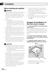
... desired installation location. In such cases, the amplifier shuts down . ! Insert the supplied tapping screws (4 mm × 18 mm) into the screw holes and push on the screws with the use under high-volume conditions, etc. ver, such as short-circuit may damage internal parts of installation on the chassis. 3 Install the amplifier with a screwdriver so they may result. ! fuel/brake lines, wiring) from being cut by...
... desired installation location. In such cases, the amplifier shuts down . ! Insert the supplied tapping screws (4 mm × 18 mm) into the screw holes and push on the screws with the use under high-volume conditions, etc. ver, such as short-circuit may damage internal parts of installation on the chassis. 3 Install the amplifier with a screwdriver so they may result. ! fuel/brake lines, wiring) from being cut by...
Owner's Manual
Page 11
...-to-noise ratio 98 dB (IHF-A network) Distortion 0.05 % (10 W, 1 kHz) Low pass filter: Cut off frequency 40 Hz to 500 Hz Cut off slope 12 dB/oct Bass boost: Frequency 50 Hz Level 0 dB/6 dB/12 dB Gain control: RCA 200 mV to 6.5 V Speaker 0.8 V to modifications without notice. ! The average current drawn is input. Use this unit when an audio signal is nearly the maxi-
...-to-noise ratio 98 dB (IHF-A network) Distortion 0.05 % (10 W, 1 kHz) Low pass filter: Cut off frequency 40 Hz to 500 Hz Cut off slope 12 dB/oct Bass boost: Frequency 50 Hz Level 0 dB/6 dB/12 dB Gain control: RCA 200 mV to 6.5 V Speaker 0.8 V to modifications without notice. ! The average current drawn is input. Use this unit when an audio signal is nearly the maxi-
Owner's Manual
Page 40
..., Heatherton, Victoria, 3202 Australia TEL: (03) 9586-6300 PIONEER ELECTRONICS OF CANADA, INC. 340 Ferrier Street, Unit 2, Markham, Ontario L3R 2Z5, Canada TEL: 1-877-283-5901 TEL: 905-479-4411 PIONEER ELECTRONICS DE MEXICO, S.A. PIONEER CORPORATION 1-1, Shin-ogura, Saiwai-ku, Kawasaki-shi, Kanagawa 212-0031, JAPAN PIONEER ELECTRONICS (USA) INC. LTD. 253 Alexandra Road, #04...
..., Heatherton, Victoria, 3202 Australia TEL: (03) 9586-6300 PIONEER ELECTRONICS OF CANADA, INC. 340 Ferrier Street, Unit 2, Markham, Ontario L3R 2Z5, Canada TEL: 1-877-283-5901 TEL: 905-479-4411 PIONEER ELECTRONICS DE MEXICO, S.A. PIONEER CORPORATION 1-1, Shin-ogura, Saiwai-ku, Kawasaki-shi, Kanagawa 212-0031, JAPAN PIONEER ELECTRONICS (USA) INC. LTD. 253 Alexandra Road, #04...


