
Operation Manual
Page 5
... Basic Operation 15 Advanced Operations 17 Types of effects BEAT COLOR FX/SOUND COLOR FX effect types 19 Types of BEAT EFFECT 19 List of MIDI Messages Changing the settings About the auto standby function 24 About the talk over function 24 Setting preferences 24 Additional information Troubleshooting 25 Block Diagram...
... Basic Operation 15 Advanced Operations 17 Types of effects BEAT COLOR FX/SOUND COLOR FX effect types 19 Types of BEAT EFFECT 19 List of MIDI Messages Changing the settings About the auto standby function 24 About the talk over function 24 Setting preferences 24 Additional information Troubleshooting 25 Block Diagram...

Operation Manual
Page 7
...contact a doctor immediately. c BOOTH terminals (page 8) Output terminals for a booth monitor, compatible with the fader of this unit's power on an external MIDI sequencer. 9 Kensington security slot a CONTROL terminal (page 8) This is simultaneously input to the [R] channel. 3 PHONO terminals (page 8) Connect to a...circuit pin plugs out of the reach of children and infants. To connect a device to a power amplifier, etc. If you connect a Pioneer DJ player using the included power cord. b DIGITAL MASTER OUT terminal (page 8) Outputs the master channel audio signals. En 7 When the...
...contact a doctor immediately. c BOOTH terminals (page 8) Output terminals for a booth monitor, compatible with the fader of this unit's power on an external MIDI sequencer. 9 Kensington security slot a CONTROL terminal (page 8) This is simultaneously input to the [R] channel. 3 PHONO terminals (page 8) Connect to a...circuit pin plugs out of the reach of children and infants. To connect a device to a power amplifier, etc. If you connect a Pioneer DJ player using the included power cord. b DIGITAL MASTER OUT terminal (page 8) Outputs the master channel audio signals. En 7 When the...

Operation Manual
Page 8
Connecting output terminals Pioneer DJ players OFF POWER ON AC IN RETURN R L (MONO) CH 4 PHONO CD/ LINE L CH 3 LINE CD/ LINE L SIGNAL GND CH 2 LINE CD/ LINE L CH 1 PHONO CD/ LINE L SIGNAL GND MIC2 MIDI OUT SEND R L (MONO) R MASTER1 R R R MASTER2 REC OUT LL L BOOTH TRS R... BOOTH TRS R L R CONTROL DIGITAL MASTER OUT CH3 CH1 R R 1 GND 2 HOT 3 COLD CH4 CH2 LR LR LR LR To power outlet Pioneer DJ players ! To use the fader start function, connect a control cable (page 15). Power amplifier External effector 1 (analog input (for booth monitor) ...
Connecting output terminals Pioneer DJ players OFF POWER ON AC IN RETURN R L (MONO) CH 4 PHONO CD/ LINE L CH 3 LINE CD/ LINE L SIGNAL GND CH 2 LINE CD/ LINE L CH 1 PHONO CD/ LINE L SIGNAL GND MIC2 MIDI OUT SEND R L (MONO) R MASTER1 R R R MASTER2 REC OUT LL L BOOTH TRS R... BOOTH TRS R L R CONTROL DIGITAL MASTER OUT CH3 CH1 R R 1 GND 2 HOT 3 COLD CH4 CH2 LR LR LR LR To power outlet Pioneer DJ players ! To use the fader start function, connect a control cable (page 15). Power amplifier External effector 1 (analog input (for booth monitor) ...

Operation Manual
Page 13
Operation Operation POWER s t MIC USB a a a a MASTER MIDI MIC1 CD/LINE PHONO USB CD/LINE LINE USB CD/LINE LINE USB CD/LINE PHONO USB LEVEL ON/ OFF START / STOP SETUP 1/ 2 3/ 4 5/ 6 k 7/ 8 u b b b b OVER TRIM ...
Operation Operation POWER s t MIC USB a a a a MASTER MIDI MIC1 CD/LINE PHONO USB CD/LINE LINE USB CD/LINE LINE USB CD/LINE PHONO USB LEVEL ON/ OFF START / STOP SETUP 1/ 2 3/ 4 5/ 6 k 7/ 8 u b b b b OVER TRIM ...

Operation Manual
Page 14
... FX buttons (page 17) These turn the SOUND COLOR FX effects on/off. 6 FADER START (1, 2, 3, 4) buttons (page 15) These turn the fader start /MIDI stop signals. i CROSS FADER ASSIGN (A, THRU, B) selector switch (page 15) Sets the output destination of the [MASTER] channel. 9 LEVEL control (page 15) Adjusts... control (page 16) Adjusts the level of audio signals output in damaging the unit. 14 En s ON/OFF button (page 18) Switches the MIDI function on , the effect sound is associated to this unit's settings (page 24). h Channel Fader (page 15) Adjusts the level of audio signals...
... FX buttons (page 17) These turn the SOUND COLOR FX effects on/off. 6 FADER START (1, 2, 3, 4) buttons (page 15) These turn the fader start /MIDI stop signals. i CROSS FADER ASSIGN (A, THRU, B) selector switch (page 15) Sets the output destination of the [MASTER] channel. 9 LEVEL control (page 15) Adjusts... control (page 16) Adjusts the level of audio signals output in damaging the unit. 14 En s ON/OFF button (page 18) Switches the MIDI function on , the effect sound is associated to this unit's settings (page 24). h Channel Fader (page 15) Adjusts the level of audio signals...

Operation Manual
Page 18
... unit's controls and buttons to be synchronized with this unit. Furthermore, the tempo (BPM) of sound output from the [MASTER] channel. ! Transmission of MIDI Messages on the DJ software can be sent to the button, fader or control positions is on page 24. 1 Connect this unit, see List of...RTN] selector switch. This selects the channel to a computer on which the BPM cannot be made on page 9. 2 Launch the DJ software. 3 Press the [MIDI] [ON/OFF] button. This unit can be synchronized. ! If you want to the control panel on the DJ software. ! When the [ON/OFF] button ...
... unit's controls and buttons to be synchronized with this unit. Furthermore, the tempo (BPM) of sound output from the [MASTER] channel. ! Transmission of MIDI Messages on the DJ software can be sent to the button, fader or control positions is on page 24. 1 Connect this unit, see List of...RTN] selector switch. This selects the channel to a computer on which the BPM cannot be made on page 9. 2 Launch the DJ software. 3 Press the [MIDI] [ON/OFF] button. This unit can be synchronized. ! If you want to the control panel on the DJ software. ! When the [ON/OFF] button ...

Operation Manual
Page 21
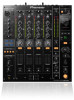
.../ 6 BEAT COLOR dB -26 / 6 BEAT COLOR MASTER LEVEL 0 OVER 10 7 4 2 1 0 - 1 - 2 - 3 - 5 - 7 -10 -15 - 24 L dB R BALANCE ON/ OFF MIDI START / STOP SETUP WAKE UP BEAT EFFECTS 1 MIC AUTO TAP CH SELECT 23 AB PARAMETER 4 MST BPM % ms BEAT AUTO / TAP TAP LOW HI CUE... EQ TIME A THRU B A THRU B A THRU B A THRU B CH FADER LEVEL / DEPTH 0 PHONES CROSS FADER ASSIGN A B CROSS FADER MIN MAX ON / OFF DJM-850 Effector BEAT c, d buttons (parameter 1) - En 21 TIME control (parameter 2) Use this to set an effect time of 1/16 - 16/1 with the [1, 2, 3, 4, MIC...
.../ 6 BEAT COLOR dB -26 / 6 BEAT COLOR MASTER LEVEL 0 OVER 10 7 4 2 1 0 - 1 - 2 - 3 - 5 - 7 -10 -15 - 24 L dB R BALANCE ON/ OFF MIDI START / STOP SETUP WAKE UP BEAT EFFECTS 1 MIC AUTO TAP CH SELECT 23 AB PARAMETER 4 MST BPM % ms BEAT AUTO / TAP TAP LOW HI CUE... EQ TIME A THRU B A THRU B A THRU B A THRU B CH FADER LEVEL / DEPTH 0 PHONES CROSS FADER ASSIGN A B CROSS FADER MIN MAX ON / OFF DJM-850 Effector BEAT c, d buttons (parameter 1) - En 21 TIME control (parameter 2) Use this to set an effect time of 1/16 - 16/1 with the [1, 2, 3, 4, MIC...

Operation Manual
Page 22
...Trigger/Toggle - - - 0-127 OFF=0, ON=127 0-127 0, 64, 127 0-127 CH FADER ( , , ) Switch CC 094 - Trigger/Toggle - - Category SW Name SW Type MIDI assignment Trigger/Toggle Transmitted data TRIM Control CC 001 - 0-127 HI Control CC 002 - 0-127 MID Control CC 003 - 0-127 LOW Control CC 004 - 0-127... Control Button CC 024 CC 023 CC 074 CC 033 CC 025 CC 076 - - On this unit, values from 0 to transmit various types of MIDI Messages ! MID Control CC 092 - 0, 64, 127 0-127 0-127 0-127 LOW Control CC 082 - 0-127 CH4 BEAT Button CC 104 Trigger/Toggle...
...Trigger/Toggle - - - 0-127 OFF=0, ON=127 0-127 0, 64, 127 0-127 CH FADER ( , , ) Switch CC 094 - Trigger/Toggle - - Category SW Name SW Type MIDI assignment Trigger/Toggle Transmitted data TRIM Control CC 001 - 0-127 HI Control CC 002 - 0-127 MID Control CC 003 - 0-127 LOW Control CC 004 - 0-127... Control Button CC 024 CC 023 CC 074 CC 033 CC 025 CC 076 - - On this unit, values from 0 to transmit various types of MIDI Messages ! MID Control CC 092 - 0, 64, 127 0-127 0-127 0-127 LOW Control CC 082 - 0-127 CH4 BEAT Button CC 104 Trigger/Toggle...

Operation Manual
Page 23
.../Toggle Trigger/Toggle Trigger/Toggle - - - - TIME value (When FLANGER, PHASER or FILTER is selected, the value is set to off, MIDI on message is selected at BEAT EFFECT HI LOW NOISE GATE CRUSH FILTER FADER START 1 FADER START 2 FADER START 3 FADER START 4 MIXING ... 0, PLAY = 127 Fader Start FADER START 2 FADER START 3 Note 103 - BACK CUE = 0, PLAY = 127 START Button START - - The MIDI Snapshot sends all MIDI messages other than MIDI start and MIDI stop. BACK CUE = 0, PLAY = 127 BACK CUE = 0, PLAY = 127 FADER START 4 Note 105 - When a negative value is selected, it...
.../Toggle Trigger/Toggle Trigger/Toggle - - - - TIME value (When FLANGER, PHASER or FILTER is selected, the value is set to off, MIDI on message is selected at BEAT EFFECT HI LOW NOISE GATE CRUSH FILTER FADER START 1 FADER START 2 FADER START 3 FADER START 4 MIXING ... 0, PLAY = 127 Fader Start FADER START 2 FADER START 3 Note 103 - BACK CUE = 0, PLAY = 127 START Button START - - The MIDI Snapshot sends all MIDI messages other than MIDI start and MIDI stop. BACK CUE = 0, PLAY = 127 BACK CUE = 0, PLAY = 127 FADER START 4 Note 105 - When a negative value is selected, it...

Operation Manual
Page 24
...4 Press the [BEAT c, d] button. To close the [CLUB SETUP] screen, press the [POWER] button to this unit's power off . Selects the MIDI signal transmission mode, [TGL (TOGGLE)] or [TRG (TRIGGER)]. The screen switches to output the microphone's audio signals from [BOOTH] terminals. Enter the setting ...auto standby function on . Change the setting value. 5 Press the [TAP] button. ON*, OFF USER SETUP CLUB SETUP MIDI CH MIDI CH MIDI Button Type MIDI BT Talk Over Mode TLK MOD Talk Over LEVEL TLK LVL Digital Master Out Level Digital Master Out Sampling Rate DOUT LV DOUT...
...4 Press the [BEAT c, d] button. To close the [CLUB SETUP] screen, press the [POWER] button to this unit's power off . Selects the MIDI signal transmission mode, [TGL (TOGGLE)] or [TRG (TRIGGER)]. The screen switches to output the microphone's audio signals from [BOOTH] terminals. Enter the setting ...auto standby function on . Change the setting value. 5 Press the [TAP] button. ON*, OFF USER SETUP CLUB SETUP MIDI CH MIDI CH MIDI Button Type MIDI BT Talk Over Mode TLK MOD Talk Over LEVEL TLK LVL Digital Master Out Level Digital Master Out Sampling Rate DOUT LV DOUT...

Operation Manual
Page 25
... the items below . No sound or small sound. Is the sound level output from this component, check the points below , ask your nearest Pioneer authorized service center or your DJ software's operating instructions. Turn the [1, 2, 3, 4, MIC, CF.A, CF.B, MASTER] selector switch to select...(BPM) differs from an external effector. Problem Check Remedy The power is measured. Clean the terminals and plugs before making settings for [MIDI]. (Operating DJ software using the included USB cable. (page 9) Select this unit's audio input terminals and the DJ player's audio ...
... the items below . No sound or small sound. Is the sound level output from this component, check the points below , ask your nearest Pioneer authorized service center or your DJ software's operating instructions. Turn the [1, 2, 3, 4, MIC, CF.A, CF.B, MASTER] selector switch to select...(BPM) differs from an external effector. Problem Check Remedy The power is measured. Clean the terminals and plugs before making settings for [MIDI]. (Operating DJ software using the included USB cable. (page 9) Select this unit's audio input terminals and the DJ player's audio ...

Operation Manual
Page 28
...RCA pin jacks 1 set SEND output terminal Phone jack (Ø 6.3 mm 1 set DIGITAL MASTER OUT coaxial output terminal RCA pin jacks 1 set MIDI OUT terminal 5P DIN 1 set PHONES output terminal Stereo phone jack (Ø 6.3 mm 1 set USB terminal B type 1 set CONTROL terminal Mini...lb) Max. The specifications and design of Microsoft Corporation in the U.S. Apple, Macintosh and Mac OS are trademarks or registered trademarks of the PIONEER CORPORATION. ! For connection with an unbalanced input (such as RCA), use the [MASTER1] terminals only for a balanced output. Connection with ...
...RCA pin jacks 1 set SEND output terminal Phone jack (Ø 6.3 mm 1 set DIGITAL MASTER OUT coaxial output terminal RCA pin jacks 1 set MIDI OUT terminal 5P DIN 1 set PHONES output terminal Stereo phone jack (Ø 6.3 mm 1 set USB terminal B type 1 set CONTROL terminal Mini...lb) Max. The specifications and design of Microsoft Corporation in the U.S. Apple, Macintosh and Mac OS are trademarks or registered trademarks of the PIONEER CORPORATION. ! For connection with an unbalanced input (such as RCA), use the [MASTER1] terminals only for a balanced output. Connection with ...

