Owner's Manual
Page 3
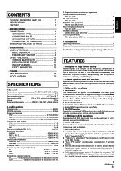
...output systems. Provided with two each of the three bandwidths HI, MID, and LOW, and a kill function is detected. 6 Other functions ¶ A control cable can be used to connect the unit to a Pioneer DJ... of effects 1) Beat effects The "beat effects" so popular on the DJM-600 have been given further evolution. Some of six input systems, together ... BEFORE USING CONNECTIONS 4 CONNECTION PANEL 4 CONNECTING INPUTS 5 CONNECTING OUTPUTS 5 CONNECTING THE POWER CORD 5 NAMES AND FUNCTIONS OF PARTS 6 OPERATIONS MIXER OPERATIONS 8 BASIC OPERATIONS 8 FADER START FUNCTION 9 EFFECT FUNCTIONS ...
...output systems. Provided with two each of the three bandwidths HI, MID, and LOW, and a kill function is detected. 6 Other functions ¶ A control cable can be used to connect the unit to a Pioneer DJ... of effects 1) Beat effects The "beat effects" so popular on the DJM-600 have been given further evolution. Some of six input systems, together ... BEFORE USING CONNECTIONS 4 CONNECTION PANEL 4 CONNECTING INPUTS 5 CONNECTING OUTPUTS 5 CONNECTING THE POWER CORD 5 NAMES AND FUNCTIONS OF PARTS 6 OPERATIONS MIXER OPERATIONS 8 BASIC OPERATIONS 8 FADER START FUNCTION 9 EFFECT FUNCTIONS ...
Owner's Manual
Page 4
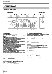
... players. MASTER OUT 1 output connectors RCA type unbalanced output. 17. Headphones jack (PHONES) Use to perform fader start play and back cue on the channel 1 DJ CD player. 8. POWER switch 2. MIC/AUX input selector switch When this connection is made , the DJ mixer's fader lever can be ...used to connect a DJ CD player or other component with line level output. 6. Channel 2 CONTROL connector Ø3.5 mm mini-phone type connector. Use to [AUX], the ...
... players. MASTER OUT 1 output connectors RCA type unbalanced output. 17. Headphones jack (PHONES) Use to perform fader start play and back cue on the channel 1 DJ CD player. 8. POWER switch 2. MIC/AUX input selector switch When this connection is made , the DJ mixer's fader lever can be ...used to connect a DJ CD player or other component with line level output. 6. Channel 2 CONTROL connector Ø3.5 mm mini-phone type connector. Use to [AUX], the ...
Owner's Manual
Page 5
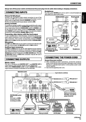
CONNECTING INPUTS Pioneer DJ CD players Connect a DJ CD player's audio output connectors to connect headphones with line level output connectors. Auxiliary input connectors The MIC1 and MIC2 jacks can also be used to one of L+R channels. Headphones The front panel ...L LINE PHONO R L LINE PHONO R CONTROL CD SIGNAL GND CONTROL PHONO/LINE switch Note: Set switch to the DJM-400's SIGNAL GND terminal. Then set to [PHONO/LINE]. CONNECTING OUTPUTS Master output This unit is set the corresponding channel's PHONO/ LINE switch to [LINE], and the input selector switch to [MONO],...
CONNECTING INPUTS Pioneer DJ CD players Connect a DJ CD player's audio output connectors to connect headphones with line level output connectors. Auxiliary input connectors The MIC1 and MIC2 jacks can also be used to one of L+R channels. Headphones The front panel ...L LINE PHONO R L LINE PHONO R CONTROL CD SIGNAL GND CONTROL PHONO/LINE switch Note: Set switch to the DJM-400's SIGNAL GND terminal. Then set to [PHONO/LINE]. CONNECTING OUTPUTS Master output This unit is set the corresponding channel's PHONO/ LINE switch to [LINE], and the input selector switch to [MONO],...
Owner's Manual
Page 6
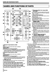
... LEVEL 13 dial (LOW) Use to adjust the bass (low-range) frequency sound for each channel (includes kill function). (Adjustable 24 3 2 CHANNEL DJ MIXER 3 14 range: -∞ to +9 dB) 0 0 7 Channel level indicators MIC 2 LEVEL + 9 BEAT EFFECTS + 9 Display the current level... to cross fader). ¶ When the cross fader selector switch is at the middle ( ) or right ( ) position, the function is heard). 12 Cross fader lever Outputs channel 1 and channel 2 sounds in a monaural display. HEADPHONES CH-1 CH-2 MASTER 28 29 LEVEL 0 FADER START 9 10 9 8 7 8 6 5 4 3 2 1 0 THRU 10...
... LEVEL 13 dial (LOW) Use to adjust the bass (low-range) frequency sound for each channel (includes kill function). (Adjustable 24 3 2 CHANNEL DJ MIXER 3 14 range: -∞ to +9 dB) 0 0 7 Channel level indicators MIC 2 LEVEL + 9 BEAT EFFECTS + 9 Display the current level... to cross fader). ¶ When the cross fader selector switch is at the middle ( ) or right ( ) position, the function is heard). 12 Cross fader lever Outputs channel 1 and channel 2 sounds in a monaural display. HEADPHONES CH-1 CH-2 MASTER 28 29 LEVEL 0 FADER START 9 10 9 8 7 8 6 5 4 3 2 1 0 THRU 10...
Owner's Manual
Page 7
...If the TAP button is tapped in the AUTO mode, the mode automatically switches to monitor with headphones. When effects are applied (P. 11). Headphones output section 28 Headphone cue button/indicator (CH-1, CH-2, MASTER) Press the button for the left channel (AUX(L)). 25 Microphone 2 level control dial...-∞ to 0 dB) When the connection panel's MIC/AUX switch is set to ON. 29 Headphones level adjust dial (LEVEL) Adjusts the output level of effect (P. 10 to which the TAP button is maximized. When rotated fully counterclockwise, attenuation of low-range sound is struck. SELECT ...
...If the TAP button is tapped in the AUTO mode, the mode automatically switches to monitor with headphones. When effects are applied (P. 11). Headphones output section 28 Headphone cue button/indicator (CH-1, CH-2, MASTER) Press the button for the left channel (AUX(L)). 25 Microphone 2 level control dial...-∞ to 0 dB) When the connection panel's MIC/AUX switch is set to ON. 29 Headphones level adjust dial (LEVEL) Adjusts the output level of effect (P. 10 to which the TAP button is maximized. When rotated fully counterclockwise, attenuation of low-range sound is struck. SELECT ...
Owner's Manual
Page 8
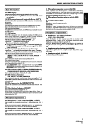
...sound volume of MIC 1, and the MIC 2 LEVEL dial to be set using the cross fader, set to [MONO], the master output becomes a monaural combination of two characteristic curves. 7 Use the cross fader selector switch to select the desired cross fader response curve. ... fader lever to choose the connected component. ¶ The function of the PHONO/LINE input connectors is produced as soon as AUX(R) input. 2. MIXER OPERATIONS (BASIC OPERATIONS) MIXER OPERATIONS BASIC OPERATIONS 2 MIC 3 TRIM 4 HI, MID, LOW 1 POWER MASTER BEAT EFFECTS 7 MASTER LEVEL HEADPHONES 5 [MIC] [AUX] MIC...
...sound volume of MIC 1, and the MIC 2 LEVEL dial to be set using the cross fader, set to [MONO], the master output becomes a monaural combination of two characteristic curves. 7 Use the cross fader selector switch to select the desired cross fader response curve. ... fader lever to choose the connected component. ¶ The function of the PHONO/LINE input connectors is produced as soon as AUX(R) input. 2. MIXER OPERATIONS (BASIC OPERATIONS) MIXER OPERATIONS BASIC OPERATIONS 2 MIC 3 TRIM 4 HI, MID, LOW 1 POWER MASTER BEAT EFFECTS 7 MASTER LEVEL HEADPHONES 5 [MIC] [AUX] MIC...
Owner's Manual
Page 10
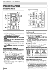
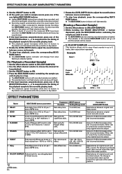
... with fadeout. For example, when a 1/1 beat echo sound is used to set the time parameters, an even wider assortment of 1/2, 3/4, 1/1, 2/1 or 4/1 beat are recorded and output repetitively.
... with fadeout. For example, when a 1/1 beat echo sound is used to set the time parameters, an even wider assortment of 1/2, 3/4, 1/1, 2/1 or 4/1 beat are recorded and output repetitively.
Owner's Manual
Page 12
... cycle for flanger effect shift. 10 to 4/1 per 1 beat of phaser effect shift is output. 6 ROBOT Robot sound effects can be erased. 8. When dial is turned fully counterclockwise, only original sound is output. 5 PHASER Cycle of BPM time. When dial is turned fully counterclockwise, only original sound is...4-beat sounds in unit of 1/1 to 16/1 relative to +100 %. IN-LOOP SAMPLER This function allows you wish to 5 banks, then output them repeatedly. Amount of the center position. 12 En No change is produced when dial is turned toward the right side of effect increases when...
... cycle for flanger effect shift. 10 to 4/1 per 1 beat of phaser effect shift is output. 6 ROBOT Robot sound effects can be erased. 8. When dial is turned fully counterclockwise, only original sound is output. 5 PHASER Cycle of BPM time. When dial is turned fully counterclockwise, only original sound is...4-beat sounds in unit of 1/1 to 16/1 relative to +100 %. IN-LOOP SAMPLER This function allows you wish to 5 banks, then output them repeatedly. Amount of the center position. 12 En No change is produced when dial is turned toward the right side of effect increases when...
Owner's Manual
Page 13
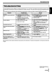
...played. ÷ Connect correctly. ÷ Clean soiled jacks/plugs before connecting. ÷ Adjust master output level (MASTER LEVEL) dial. ÷ Adjust the TRIM dial so that the input level approaches 0... the TAP button to the CD player. ÷ Effect channel selector (CH. Published by Pioneer Corporation. Sometimes the trouble may originate from the value published with some tracks. ÷ Some...the FADER START button to ON. ÷ Use a control cable to connect the CONTROL jacks of DJM-400 and CD player. ÷ Connect both the CONTROL jacks and CD input connectors. ÷ Correctly...
...played. ÷ Connect correctly. ÷ Clean soiled jacks/plugs before connecting. ÷ Adjust master output level (MASTER LEVEL) dial. ÷ Adjust the TRIM dial so that the input level approaches 0... the TAP button to the CD player. ÷ Effect channel selector (CH. Published by Pioneer Corporation. Sometimes the trouble may originate from the value published with some tracks. ÷ Some...the FADER START button to ON. ÷ Use a control cable to connect the CONTROL jacks of DJM-400 and CD player. ÷ Connect both the CONTROL jacks and CD input connectors. ÷ Correctly...
Owner's Manual
Page 76
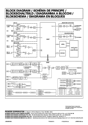
... 3195, Australia TEL: +61-3-9586-6300 PIONEER ELECTRONICS ASIACENTRE PTE. C.P. 11000 TEL: 52-55-9178-4270 Printed in / Imprimé au PIONEER CORPORATION 4-1, Meguro 1-Chome, Meguro-ku, Tokyo 153-8654, Japan PIONEER EUROPE NV MULTIMEDIA DIVISION Pioneer House Hollybush Hill, Stoke Poges, Slough SL2...1 LEVEL MIC 1 AUX L ADC MIC 2/ AUX R MIC 2 LEVEL MIC 2 AUX R CH-1 Master out CH-2 H.P out DSP MIC 1 MIC 2 [MASTER OUTPUTS] MUTE DAC MASTER OUT 1 MASTER OUT 2 [HEADPHONES] MUTE DAC PHONES CPU SDRAM SWITCHES & INDICATORS CH-1 CH-2 MIC 1 MIC 2 BPM detect [CH1] 3-Band ...
... 3195, Australia TEL: +61-3-9586-6300 PIONEER ELECTRONICS ASIACENTRE PTE. C.P. 11000 TEL: 52-55-9178-4270 Printed in / Imprimé au PIONEER CORPORATION 4-1, Meguro 1-Chome, Meguro-ku, Tokyo 153-8654, Japan PIONEER EUROPE NV MULTIMEDIA DIVISION Pioneer House Hollybush Hill, Stoke Poges, Slough SL2...1 LEVEL MIC 1 AUX L ADC MIC 2/ AUX R MIC 2 LEVEL MIC 2 AUX R CH-1 Master out CH-2 H.P out DSP MIC 1 MIC 2 [MASTER OUTPUTS] MUTE DAC MASTER OUT 1 MASTER OUT 2 [HEADPHONES] MUTE DAC PHONES CPU SDRAM SWITCHES & INDICATORS CH-1 CH-2 MIC 1 MIC 2 BPM detect [CH1] 3-Band ...
