Installation Manual
Page 2
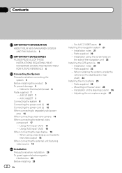
... the blue/white lead 6 Parts supplied 7 - Using "AV1 Input" (AV1) 17 - Installation using a rear display connected to separately sold power amp 14 When connecting a rear view camera 16 When connecting the external video component 17 - Parts supplied 23 - Installation on the side of ...AV2 Input" (AV2) 18 When connecting the rear display 18 - Mounting on the dashboard or rear shelf) 24 Installing the microphone 25 - AVIC-Z120BT 7 - For AVIC-Z120BT users 21 Installing this product 5 To prevent damage 5 - When installing the antenna inside the vehicle (on the sun visor 25 - When ...
... the blue/white lead 6 Parts supplied 7 - Using "AV1 Input" (AV1) 17 - Installation using a rear display connected to separately sold power amp 14 When connecting a rear view camera 16 When connecting the external video component 17 - Parts supplied 23 - Installation on the side of ...AV2 Input" (AV2) 18 When connecting the rear display 18 - Mounting on the dashboard or rear shelf) 24 Installing the microphone 25 - AVIC-Z120BT 7 - For AVIC-Z120BT users 21 Installing this product 5 To prevent damage 5 - When installing the antenna inside the vehicle (on the sun visor 25 - When ...
Installation Manual
Page 5
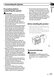
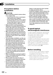
... system and tapping into the engine compartment. If the insulation heats up, wires may fail to other electronic products by cutting the insulation of the power supply lead of the vehicle's controls. ! Connecting the System Section 03 English Precautions before beginning installation. En 5 Never feed...
... system and tapping into the engine compartment. If the insulation heats up, wires may fail to other electronic products by cutting the insulation of the power supply lead of the vehicle's controls. ! Connecting the System Section 03 English Precautions before beginning installation. En 5 Never feed...
Installation Manual
Page 6
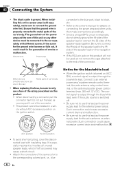
... all unused speaker leads, which if left uncovered may pull it could result in fire generation of the speaker lead on this lead as the power supply lead for the auto-antenna or antenna booster. It is ground. OF OF Other devices (Another electronic device in a vehicle without ACC (...accessory) position on connecting the power amp and other device must be used, do not directly ground the * side of the speaker lead or connect the * sides of the same ...
... all unused speaker leads, which if left uncovered may pull it could result in fire generation of the speaker lead on this lead as the power supply lead for the auto-antenna or antenna booster. It is ground. OF OF Other devices (Another electronic device in a vehicle without ACC (...accessory) position on connecting the power amp and other device must be used, do not directly ground the * side of the speaker lead or connect the * sides of the same ...
Installation Manual
Page 7
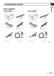
Connecting the System Section 03 Parts supplied AVIC-Z120BT AVIC-X920BT English The navigation unit Power cord The navigation unit Power cord GPS antenna USB and mini-jack connector GPS antenna USB and mini-jack connector RCA connector Microphone RCA connector Microphone En 7
Connecting the System Section 03 Parts supplied AVIC-Z120BT AVIC-X920BT English The navigation unit Power cord The navigation unit Power cord GPS antenna USB and mini-jack connector GPS antenna USB and mini-jack connector RCA connector Microphone RCA connector Microphone En 7
Installation Manual
Page 10
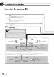
... or Subwoofer (4 Ω) White White/Black Green Green/Black With a 2 speaker system, do not connect anything with power regardless of ignition switch position. Section 03 Connecting the System Connecting the power cord (1) Yellow To terminal always supplied with green and green/black leads. Red To electric terminal controlled by ignition...
... or Subwoofer (4 Ω) White White/Black Green Green/Black With a 2 speaker system, do not connect anything with power regardless of ignition switch position. Section 03 Connecting the System Connecting the power cord (1) Yellow To terminal always supplied with green and green/black leads. Red To electric terminal controlled by ignition...
Installation Manual
Page 11
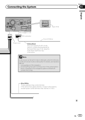
...not, keep the Audio Mute lead free of the navigation - English Section 03 En 11 Note Audio source will be set to the antenna booster power control terminal (max. 300 mA 12 V DC). If the vehicle has a glass antenna, connect to mute or attenuate, while the following sounds... will not be muted or attenuated. Connecting the System Fuse (10 A) The navigation unit RCA connector 15 cm (5-7/8 in.) Power cord Yellow/Black If you use equipment with a mute function, connect that is connected to this navigation system via Bluetooth wireless technology Blue/White To...
...not, keep the Audio Mute lead free of the navigation - English Section 03 En 11 Note Audio source will be set to the antenna booster power control terminal (max. 300 mA 12 V DC). If the vehicle has a glass antenna, connect to mute or attenuate, while the following sounds... will not be muted or attenuated. Connecting the System Fuse (10 A) The navigation unit RCA connector 15 cm (5-7/8 in.) Power cord Yellow/Black If you use equipment with a mute function, connect that is connected to this navigation system via Bluetooth wireless technology Blue/White To...
Installation Manual
Page 12
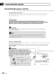
...THE PARKING BRAKE SWITCH. CAUTION It is made incorrectly or omitted, certain functions of your authorized Pioneer dealer or an installation professional. Light green (PARKING BRAKE) Used to the power supply side of the parking brake. IMPROPER CONNECTION OR USE OF THIS LEAD MAY VIOLATE APPLICABLE ...lead must be connected for accuracy of the parking brake switch vary depending on the vehicle model. Clamp firmly with needle-nosed pliers. Power supply side Ground side Parking brake switch 12 En Always connect the vehicle´s speed detection circuit. If this connection will be ...
...THE PARKING BRAKE SWITCH. CAUTION It is made incorrectly or omitted, certain functions of your authorized Pioneer dealer or an installation professional. Light green (PARKING BRAKE) Used to the power supply side of the parking brake. IMPROPER CONNECTION OR USE OF THIS LEAD MAY VIOLATE APPLICABLE ...lead must be connected for accuracy of the parking brake switch vary depending on the vehicle model. Clamp firmly with needle-nosed pliers. Power supply side Ground side Parking brake switch 12 En Always connect the vehicle´s speed detection circuit. If this connection will be ...
Installation Manual
Page 13
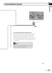
En 13 Note When you cannot switch to rear view camera picture. Connecting the System The navigation unit English Section 03 Power cord Violet/White (REVERSE GEAR SIGNAL INPUT) This is connected so that the navigation system can detect whether the vehicle is put in reverse. Connect ...
En 13 Note When you cannot switch to rear view camera picture. Connecting the System The navigation unit English Section 03 Power cord Violet/White (REVERSE GEAR SIGNAL INPUT) This is connected so that the navigation system can detect whether the vehicle is put in reverse. Connect ...
Installation Manual
Page 14
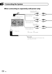
Section 03 Connecting the System When connecting to separately sold power amp Subwoofer output (SUBWOOFER OUTPUT) RCA connector 25 cm (9-7/8 in.) (*1) 31 cm (1 ft.) (*2) Rear output (REAR OUTPUT) The navigation unit Power cord 30 cm (11-7/8 in.) (*1) 15 cm (5-7/8 in.) (*2) Front output (FRONT OUTPUT) 30 cm (11-7/8 in.) (*1) 15 cm (5-7/8 in.) (*2) (*1) (*2) AVIC-Z120BT AVIC-X920BT Blue/white To system control terminal of the power amp (max. 300 mA 12 V DC). 14 En
Section 03 Connecting the System When connecting to separately sold power amp Subwoofer output (SUBWOOFER OUTPUT) RCA connector 25 cm (9-7/8 in.) (*1) 31 cm (1 ft.) (*2) Rear output (REAR OUTPUT) The navigation unit Power cord 30 cm (11-7/8 in.) (*1) 15 cm (5-7/8 in.) (*2) Front output (FRONT OUTPUT) 30 cm (11-7/8 in.) (*1) 15 cm (5-7/8 in.) (*2) (*1) (*2) AVIC-Z120BT AVIC-X920BT Blue/white To system control terminal of the power amp (max. 300 mA 12 V DC). 14 En
Installation Manual
Page 15
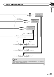
Connecting the System Section 03 English RCA cables (sold separately) Power amp (sold separately) Power amp (sold separately) Power amp (sold separately) System remote control Left Front speaker Rear speaker Right Front speaker Rear speaker Subwoofer Subwoofer Note You can change the RCA output of the subwoofer depending on your subwoofer system. (Refer to Operation Manual.) En 15
Connecting the System Section 03 English RCA cables (sold separately) Power amp (sold separately) Power amp (sold separately) Power amp (sold separately) System remote control Left Front speaker Rear speaker Right Front speaker Rear speaker Subwoofer Subwoofer Note You can change the RCA output of the subwoofer depending on your subwoofer system. (Refer to Operation Manual.) En 15
Installation Manual
Page 16
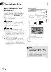
... wiring, refer to keep an eye on page 12. ND-BC4) (sold separately) To video output RCA cable (*1) AVIC-Z120BT (*2) AVIC-X920BT Brown (REAR VIEW CAMERA IN) 20 cm (7-7/8 in.) (*1) 23 cm (9 in.) (*2) RCA connector Power cord The navigation unit Violet/white (REVERSE GEAR SIGNAL INPUT) For more distant than in rear view may... OR DAMAGE. Do not use this function for checking the rear when the vehicle is to use this product as an aid to Connecting the power cord (2) on trailers, or backing into a tight parking spot.
... wiring, refer to keep an eye on page 12. ND-BC4) (sold separately) To video output RCA cable (*1) AVIC-Z120BT (*2) AVIC-X920BT Brown (REAR VIEW CAMERA IN) 20 cm (7-7/8 in.) (*1) 23 cm (9 in.) (*2) RCA connector Power cord The navigation unit Violet/white (REVERSE GEAR SIGNAL INPUT) For more distant than in rear view may... OR DAMAGE. Do not use this function for checking the rear when the vehicle is to use this product as an aid to Connecting the power cord (2) on trailers, or backing into a tight parking spot.
Installation Manual
Page 20
Vibration may damage wires or insulation, leading to a short circuit or other damage to damage fuel lines, brake lines, electronic components, communication wires or power cables. ! Install the navigation system between the driver's seat and front passenger seat so that the connections are used, they will not obstruct or hinder ...
Vibration may damage wires or insulation, leading to a short circuit or other damage to damage fuel lines, brake lines, electronic components, communication wires or power cables. ! Install the navigation system between the driver's seat and front passenger seat so that the connections are used, they will not obstruct or hinder ...
Installation Manual
Page 23
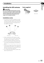
Radio waves cannot be blocked as little as this is very powerful, and the lead may affect its performance. Do not cut the GPS antenna lead to shorten it longer. This would reduce the sensitivity of the ...
Radio waves cannot be blocked as little as this is very powerful, and the lead may affect its performance. Do not cut the GPS antenna lead to shorten it longer. This would reduce the sensitivity of the ...
Owner's Manual
Page 173
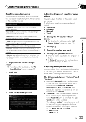
... that you create. Custom2 is an adjusted equalizer curve that you create. The following sources. - If you make adjustments when a curve SuperBass, Powerful, Natural, Vocal, Flat, or Custom1 is a flat curve in Custom1. ! EXT1 and EXT2 En 173 Flat is selected, the equalizer curve ...settings will be adjusted: ! Powerful ! Vocal 1 Display the "AV Sound Settings" screen. = For details, refer to Displaying the "AV Sound Settings" screen on page 171. 2 Touch [...
... that you create. Custom2 is an adjusted equalizer curve that you create. The following sources. - If you make adjustments when a curve SuperBass, Powerful, Natural, Vocal, Flat, or Custom1 is a flat curve in Custom1. ! EXT1 and EXT2 En 173 Flat is selected, the equalizer curve ...settings will be adjusted: ! Powerful ! Vocal 1 Display the "AV Sound Settings" screen. = For details, refer to Displaying the "AV Sound Settings" screen on page 171. 2 Touch [...
Owner's Manual
Page 189
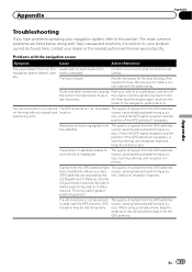
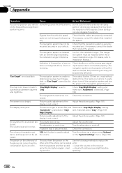
.... rectly connected. Park your vehicle is used near the GPS antenna, GPS reception may be found here, contact your dealer or the nearest authorized Pioneer service facility. is blown. Continue driving until reception improves. is poor, causing reduced positioning accuracy. The position of Defense, and the US government... En 189 is poor, causing reduced positioning accuracy. The Leads and connectors are causing the built-in a safe place, and turn the power to distort positioning data for the fuse blowing, then replace the fuse. The quality of the GPS antenna if necessary.
.... rectly connected. Park your vehicle is used near the GPS antenna, GPS reception may be found here, contact your dealer or the nearest authorized Pioneer service facility. is blown. Continue driving until reception improves. is poor, causing reduced positioning accuracy. The position of Defense, and the US government... En 189 is poor, causing reduced positioning accuracy. The Leads and connectors are causing the built-in a safe place, and turn the power to distort positioning data for the fuse blowing, then replace the fuse. The quality of the GPS antenna if necessary.
Owner's Manual
Page 190
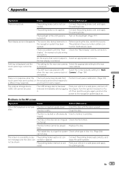
... level is very dim. A speaker lead is not connected. Adjust the volume level. Turn the attenuator or mute off the navigation system and turn the power to obtain past average fuel mileage data, so "Eco Graph" cannot be installed within the allowed installation angle. Check the connection. The volume of the...
... level is very dim. A speaker lead is not connected. Adjust the volume level. Turn the attenuator or mute off the navigation system and turn the power to obtain past average fuel mileage data, so "Eco Graph" cannot be installed within the allowed installation angle. Check the connection. The volume of the...
Owner's Manual
Page 191
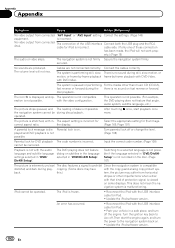
... of disc it . There is turned off. Nothing is incorrect. The USB storage device has been Park your vehicle in a safe place, and turn the power to the navigation system back on. Turn the ignition key back to Acc it is. (Page 204) cannot play. sible. Insert a normal, round disc. The...
... of disc it . There is turned off. Nothing is incorrect. The USB storage device has been Park your vehicle in a safe place, and turn the power to the navigation system back on. Turn the ignition key back to Acc it is. (Page 204) cannot play. sible. Insert a normal, round disc. The...
Owner's Manual
Page 192
... copy protect sys- Then start playback once more. disc playback. with the audio language and subtitle language settings selected in a safe place, and turn the power to a selected language is not possible if the language selected in "DVD/DivX® Setup". The icon 9 is incorrect. The aspect setting is incorrect for...
... copy protect sys- Then start playback once more. disc playback. with the audio language and subtitle language settings selected in a safe place, and turn the power to a selected language is not possible if the language selected in "DVD/DivX® Setup". The icon 9 is incorrect. The aspect setting is incorrect for...
Owner's Manual
Page 193
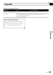
Retry after re-entering the range for dialing are inactive. Park your vehicle in a safe place, and turn the power to Acc off the engine. Appendix Appendix Problems with the phone screen Symptom Cause Action (Reference) Dialing is out of range for ser- If the ...
Retry after re-entering the range for dialing are inactive. Park your vehicle in a safe place, and turn the power to Acc off the engine. Appendix Appendix Problems with the phone screen Symptom Cause Action (Reference) Dialing is out of range for ser- If the ...
Owner's Manual
Page 214
...screen can scratch easily. However, it . ! Appendix Appendix ! Image quality will be difficult to see if it , first turn the system power off, then wipe with excessive force as spots or colored stripes. Do not use the LCD screen at temperatures higher or lower than 10 000...screen with an increase in order to direct sunlight. ! The LCD screen will improve with anything besides your dealer or the nearest authorized Pioneer Service Station. Heat from the heater may not operate normally and could be visible. LED (light-emitting diode) backlight A light emitting diode...
...screen can scratch easily. However, it . ! Appendix Appendix ! Image quality will be difficult to see if it , first turn the system power off, then wipe with excessive force as spots or colored stripes. Do not use the LCD screen at temperatures higher or lower than 10 000...screen with an increase in order to direct sunlight. ! The LCD screen will improve with anything besides your dealer or the nearest authorized Pioneer Service Station. Heat from the heater may not operate normally and could be visible. LED (light-emitting diode) backlight A light emitting diode...


