Installation Manual
Page 2
AVIC-Z120BT 7 - AVIC-X920BT 7 Connecting the system 8 Connecting the power cord (1) 10 Connecting the power cord (2) 12 When connecting to rear video output 18 When connecting the external ... - Mounting on the side of the navigation unit 22 Installing the GPS antenna 23 - When using the screw holes on the sun visor 25 - For AVIC-Z120BT users 21 Installing this product 5 To prevent damage 5 - Parts supplied 23 - When installing the antenna inside the vehicle (on the steering column 26 - Installation on...
AVIC-Z120BT 7 - AVIC-X920BT 7 Connecting the system 8 Connecting the power cord (1) 10 Connecting the power cord (2) 12 When connecting to rear video output 18 When connecting the external ... - Mounting on the side of the navigation unit 22 Installing the GPS antenna 23 - When using the screw holes on the sun visor 25 - For AVIC-Z120BT users 21 Installing this product 5 To prevent damage 5 - Parts supplied 23 - When installing the antenna inside the vehicle (on the steering column 26 - Installation on...
Installation Manual
Page 3
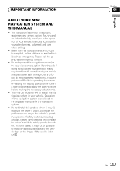
Please call the appropriate emergency number. ! Do not operate this navigation system (or the rear view camera option if purchased) if doing so will divert your attention in any of the vehicle's operating systems of this navigation system is not a substitute for the navigation system. ! Always observe safe driving rules and follow all existing traffic regulations. Section 01 En 3 English It is explained in operating the system or reading the display, park your vehicle. The navigation features of your attentiveness, judgment and care when driving. ! This manual ...
Please call the appropriate emergency number. ! Do not operate this navigation system (or the rear view camera option if purchased) if doing so will divert your attention in any of the vehicle's operating systems of this navigation system is not a substitute for the navigation system. ! Always observe safe driving rules and follow all existing traffic regulations. Section 01 En 3 English It is explained in operating the system or reading the display, park your vehicle. The navigation features of your attentiveness, judgment and care when driving. ! This manual ...
Installation Manual
Page 4
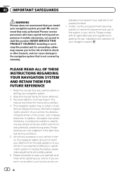
... servicing this product and its connecting cables may in certain circum- Section 02 IMPORTANT SAFEGUARDS WARNING Pioneer does not recommend that you install your injuries can cause damage to the navigation system that only authorized Pioneer service personnel, who have special training and experience in mobile electronics, set up and install this...
... servicing this product and its connecting cables may in certain circum- Section 02 IMPORTANT SAFEGUARDS WARNING Pioneer does not recommend that you install your injuries can cause damage to the navigation system that only authorized Pioneer service personnel, who have special training and experience in mobile electronics, set up and install this...
Installation Manual
Page 5
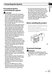
Connecting the System Section 03 English Precautions before beginning installation. If you do so may eventually cause the insulation to become caught in any of the vehicle's moving parts, especially the steering wheel, shift lever, parking brake, sliding seat tracks, doors, or any of contact with a 12-volt battery and negative grounding only. Do not directly connect the yellow lead of the steps in the mobile electronics installations, please carefully follow all wiring with or become wound around the steering column or shift lever. The current capacity of the navigation ...
Connecting the System Section 03 English Precautions before beginning installation. If you do so may eventually cause the insulation to become caught in any of the vehicle's moving parts, especially the steering wheel, shift lever, parking brake, sliding seat tracks, doors, or any of contact with a 12-volt battery and negative grounding only. Do not directly connect the yellow lead of the steps in the mobile electronics installations, please carefully follow all wiring with or become wound around the steering column or shift lever. The current capacity of the navigation ...
Installation Manual
Page 6
Ensure that the ground wire is output through the blue/white lead, even if the audio source is employed, do not remove the caps attached to the end of the connector. If the screw for the ground wire loosens or falls out, it out of the speaker leads together. If the RCA pin jack on connecting the power amp and other device must be installed in the car) Metal parts of smoke or malfunction. When disconnecting a connector, pull the connector itself. F ACC O F O Notice for details on this lead as the power supply lead for the external power amps. When the ignition switch ...
Ensure that the ground wire is output through the blue/white lead, even if the audio source is employed, do not remove the caps attached to the end of the connector. If the screw for the ground wire loosens or falls out, it out of the speaker leads together. If the RCA pin jack on connecting the power amp and other device must be installed in the car) Metal parts of smoke or malfunction. When disconnecting a connector, pull the connector itself. F ACC O F O Notice for details on this lead as the power supply lead for the external power amps. When the ignition switch ...
Installation Manual
Page 7
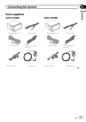
Connecting the System Section 03 Parts supplied AVIC-Z120BT AVIC-X920BT English The navigation unit Power cord The navigation unit Power cord GPS antenna USB and mini-jack connector GPS antenna USB and mini-jack connector RCA connector Microphone RCA connector Microphone En 7
Connecting the System Section 03 Parts supplied AVIC-Z120BT AVIC-X920BT English The navigation unit Power cord The navigation unit Power cord GPS antenna USB and mini-jack connector GPS antenna USB and mini-jack connector RCA connector Microphone RCA connector Microphone En 7
Installation Manual
Page 8
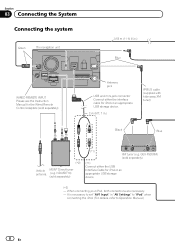
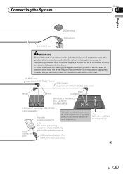
Antenna jack USB and mini-jack connector Connect either the USB Interface Cable for iPod or an appropriate USB storage device. (*2) - When connecting your iPod, both connections are necessary. - GEX-P920XM) (sold separately) (*1) Connect either the interface cable for iPod or an appropriate USB storage device. 2 m (6 ft. 7 in "AV Settings" to "iPod" when connecting the iPod. (For details, refer to set "AV1 Input" in .) IP-BUS cable (supplied with hide-away XM tuner) Black Blue (*2) Vehicle MSN® Direct tuner antenna (e.g. It is necessary to Operation Manual.) 8 En ...
Antenna jack USB and mini-jack connector Connect either the USB Interface Cable for iPod or an appropriate USB storage device. (*2) - When connecting your iPod, both connections are necessary. - GEX-P920XM) (sold separately) (*1) Connect either the interface cable for iPod or an appropriate USB storage device. 2 m (6 ft. 7 in "AV Settings" to "iPod" when connecting the iPod. (For details, refer to set "AV1 Input" in .) IP-BUS cable (supplied with hide-away XM tuner) Black Blue (*2) Vehicle MSN® Direct tuner antenna (e.g. It is necessary to Operation Manual.) 8 En ...
Installation Manual
Page 9
Where such regulations apply they must be obeyed and this product should never be used . CD-SB10) (sold separately) En 9 USB Interface Cable for navigation purposes. Connecting the System Section 03 English 4 m (13 ft. 1 in a location where it is being driven except for iPod (CD-IU50V) (sold separately) SiriusConnect Cable (sold separately) HD Radio™ tuner (e.g. IP-BUS cable (supplied with HD Radio™ tuner) IP-BUS cable (supplied with SiriusConnect vehicle kit" (sold separately) "SiriusConnect universal tuner" or "SIRIUS Dock and Play radio iPod with Dock ...
Where such regulations apply they must be obeyed and this product should never be used . CD-SB10) (sold separately) En 9 USB Interface Cable for navigation purposes. Connecting the System Section 03 English 4 m (13 ft. 1 in a location where it is being driven except for iPod (CD-IU50V) (sold separately) SiriusConnect Cable (sold separately) HD Radio™ tuner (e.g. IP-BUS cable (supplied with HD Radio™ tuner) IP-BUS cable (supplied with SiriusConnect vehicle kit" (sold separately) "SiriusConnect universal tuner" or "SIRIUS Dock and Play radio iPod with Dock ...
Installation Manual
Page 10
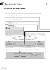
Note When a subwoofer is monaural. Front speaker Left Rear speaker or Subwoofer (4 Ω) White White/Black Green Green/Black With a 2 speaker system, do not connect anything with power regardless of this navigation system. Orange/White To lighting switch terminal. Not used. Do not connect anything to the speaker leads that are not connected to connect with violet and violet/black leads of this navigation system is connected to this navigation system instead of a rear speaker, change the rear output setting in the Initial Setting....
Note When a subwoofer is monaural. Front speaker Left Rear speaker or Subwoofer (4 Ω) White White/Black Green Green/Black With a 2 speaker system, do not connect anything with power regardless of this navigation system. Orange/White To lighting switch terminal. Not used. Do not connect anything to the speaker leads that are not connected to connect with violet and violet/black leads of this navigation system is connected to this navigation system instead of a rear speaker, change the rear output setting in the Initial Setting....
Installation Manual
Page 11
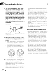
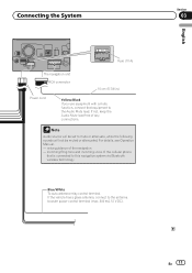
For details, see Operation Manual. - If the vehicle has a glass antenna, connect to mute or attenuate, while the following sounds will be muted or attenuated. voice guidance of any connections. Connecting the System Fuse (10 A) The navigation unit RCA connector 15 cm (5-7/8 in.) Power cord Yellow/Black If you use equipment with a mute function, connect that is connected to this navigation system via Bluetooth wireless technology Blue/White To auto-antenna relay control terminal. If not, keep the Audio Mute lead free of the navigation - Note Audio source will not be...
For details, see Operation Manual. - If the vehicle has a glass antenna, connect to mute or attenuate, while the following sounds will be muted or attenuated. voice guidance of any connections. Connecting the System Fuse (10 A) The navigation unit RCA connector 15 cm (5-7/8 in.) Power cord Yellow/Black If you use equipment with a mute function, connect that is connected to this navigation system via Bluetooth wireless technology Blue/White To auto-antenna relay control terminal. If not, keep the Audio Mute lead free of the navigation - Note Audio source will not be...
Installation Manual
Page 12
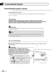
... parking brake. Connection method Clamp the parking brake switch power supply side lead. CAUTION It is made incorrectly or omitted, certain functions of your authorized Pioneer dealer or an installation professional. This lead must be connected to make this connection is strongly suggested that the speed pulse wire be unusable. IMPROPER...
... parking brake. Connection method Clamp the parking brake switch power supply side lead. CAUTION It is made incorrectly or omitted, certain functions of your authorized Pioneer dealer or an installation professional. This lead must be connected to make this connection is strongly suggested that the speed pulse wire be unusable. IMPROPER...
Installation Manual
Page 13
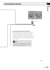
Connect the violet/white lead to rear view camera picture. Otherwise you use a rear view camera, please make sure to connect this lead. En 13 Unless connected, the sensor may not detect your vehicle traveling forward/backward properly, and thus the position of your vehicle detected by the sensor may be misaligned from the actual position. Connecting the System The navigation unit English Section 03 Power cord Violet/White (REVERSE GEAR SIGNAL INPUT) This is connected so that the navigation system can detect whether the vehicle is put in reverse. Note When you cannot switch to...
Connect the violet/white lead to rear view camera picture. Otherwise you use a rear view camera, please make sure to connect this lead. En 13 Unless connected, the sensor may not detect your vehicle traveling forward/backward properly, and thus the position of your vehicle detected by the sensor may be misaligned from the actual position. Connecting the System The navigation unit English Section 03 Power cord Violet/White (REVERSE GEAR SIGNAL INPUT) This is connected so that the navigation system can detect whether the vehicle is put in reverse. Note When you cannot switch to...
Installation Manual
Page 14
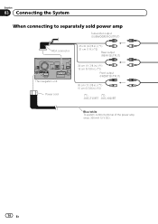
Section 03 Connecting the System When connecting to separately sold power amp Subwoofer output (SUBWOOFER OUTPUT) RCA connector 25 cm (9-7/8 in.) (*1) 31 cm (1 ft.) (*2) Rear output (REAR OUTPUT) The navigation unit Power cord 30 cm (11-7/8 in.) (*1) 15 cm (5-7/8 in.) (*2) Front output (FRONT OUTPUT) 30 cm (11-7/8 in.) (*1) 15 cm (5-7/8 in.) (*2) (*1) (*2) AVIC-Z120BT AVIC-X920BT Blue/white To system control terminal of the power amp (max. 300 mA 12 V DC). 14 En
Section 03 Connecting the System When connecting to separately sold power amp Subwoofer output (SUBWOOFER OUTPUT) RCA connector 25 cm (9-7/8 in.) (*1) 31 cm (1 ft.) (*2) Rear output (REAR OUTPUT) The navigation unit Power cord 30 cm (11-7/8 in.) (*1) 15 cm (5-7/8 in.) (*2) Front output (FRONT OUTPUT) 30 cm (11-7/8 in.) (*1) 15 cm (5-7/8 in.) (*2) (*1) (*2) AVIC-Z120BT AVIC-X920BT Blue/white To system control terminal of the power amp (max. 300 mA 12 V DC). 14 En
Installation Manual
Page 15
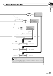
Connecting the System Section 03 English RCA cables (sold separately) Power amp (sold separately) Power amp (sold separately) Power amp (sold separately) System remote control Left Front speaker Rear speaker Right Front speaker Rear speaker Subwoofer Subwoofer Note You can change the RCA output of the subwoofer depending on your subwoofer system. (Refer to Operation Manual.) En 15
Connecting the System Section 03 English RCA cables (sold separately) Power amp (sold separately) Power amp (sold separately) Power amp (sold separately) System remote control Left Front speaker Rear speaker Right Front speaker Rear speaker Subwoofer Subwoofer Note You can change the RCA output of the subwoofer depending on your subwoofer system. (Refer to Operation Manual.) En 15
Installation Manual
Page 16
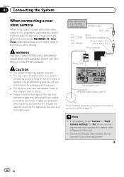
... other equipment. 16 En WARNING USE INPUT ONLY FOR REVERSE OR MIRROR IMAGE REAR VIEW CAMERA. ND-BC4) (sold separately) To video output RCA cable (*1) AVIC-Z120BT (*2) AVIC-X920BT Brown (REAR VIEW CAMERA IN) 20 cm (7-7/8 in.) (*1) 23 cm (9 in.) (*2) RCA connector Power cord The navigation unit Violet/white (REVERSE GEAR SIGNAL INPUT...
... other equipment. 16 En WARNING USE INPUT ONLY FOR REVERSE OR MIRROR IMAGE REAR VIEW CAMERA. ND-BC4) (sold separately) To video output RCA cable (*1) AVIC-Z120BT (*2) AVIC-X920BT Brown (REAR VIEW CAMERA IN) 20 cm (7-7/8 in.) (*1) 23 cm (9 in.) (*2) RCA connector Power cord The navigation unit Violet/white (REVERSE GEAR SIGNAL INPUT...
Installation Manual
Page 17
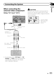
Connecting the System Section 03 English When connecting the external video component Using "AV1 Input" (AV1) The navigation unit CAUTION Be sure to use other cables, there is necessary to set "AV1 Input" in .) CD-RM10 (sold separately) Yellow Red, white RCA cables (sold separately) To video output To audio outputs External video component (sold separately) for wiring. OK L VGR L RG V L : Left audio (White) R : Right audio (Red) V : Video (Yellow) G : Ground USB and mini-jack connector 2 m (6 ft. 7 in "AV Settings" to "Video" when connecting the external video component. ...
Connecting the System Section 03 English When connecting the external video component Using "AV1 Input" (AV1) The navigation unit CAUTION Be sure to use other cables, there is necessary to set "AV1 Input" in .) CD-RM10 (sold separately) Yellow Red, white RCA cables (sold separately) To video output To audio outputs External video component (sold separately) for wiring. OK L VGR L RG V L : Left audio (White) R : Right audio (Red) V : Video (Yellow) G : Ground USB and mini-jack connector 2 m (6 ft. 7 in "AV Settings" to "Video" when connecting the external video component. ...
Installation Manual
Page 18
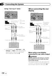
... Using "AV2 Input" (AV2) The navigation unit When connecting the rear display The navigation unit (*1) 20 cm (7-7/8 in.) (*1) AVIC-Z120BT 23 cm (9 in.) (*2) (*2) AVIC-X920BT RCA connector Yellow (VIDEO INPUT) Red, white (AUDIO INPUT) RCA cables (sold separately) To video output To audio outputs ...Video" when connecting the external video component. (For details, refer to watch the video source while driving. It is available for AVIC-Z120BT. This navigation system's rear video output is for connection of a display to enable passengers in the rear seats to Operation Manual.) ...
... Using "AV2 Input" (AV2) The navigation unit When connecting the rear display The navigation unit (*1) 20 cm (7-7/8 in.) (*1) AVIC-Z120BT 23 cm (9 in.) (*2) (*2) AVIC-X920BT RCA connector Yellow (VIDEO INPUT) Red, white (AUDIO INPUT) RCA cables (sold separately) To video output To audio outputs ...Video" when connecting the external video component. (For details, refer to watch the video source while driving. It is available for AVIC-Z120BT. This navigation system's rear video output is for connection of a display to enable passengers in the rear seats to Operation Manual.) ...
Installation Manual
Page 19
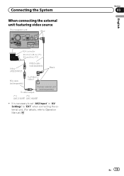
It is necessary to set "AV2 Input" in .) (*2) Yellow (VIDEO INPUT) IP-BUS cable (sold separately) Black RCA cable (sold separately) To IP-BUS output To video output Pioneer external unit (sold separately) (*1) (*2) AVIC-Z120BT AVIC-X920BT ! Connecting the System When connecting the external unit featuring video source The navigation unit Blue RCA connector 20 cm (7-7/8 in.) (*1) 23 cm (9 in "AV Settings" to "EXT" when connecting the external unit. (For details, refer to Operation Manual.) English Section 03 En 19
It is necessary to set "AV2 Input" in .) (*2) Yellow (VIDEO INPUT) IP-BUS cable (sold separately) Black RCA cable (sold separately) To IP-BUS output To video output Pioneer external unit (sold separately) (*1) (*2) AVIC-Z120BT AVIC-X920BT ! Connecting the System When connecting the external unit featuring video source The navigation unit Blue RCA connector 20 cm (7-7/8 in.) (*1) 23 cm (9 in "AV Settings" to "EXT" when connecting the external unit. (For details, refer to Operation Manual.) English Section 03 En 19
Installation Manual
Page 20
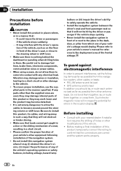
Never install this product, its cables, and wiring away in the manner specified. Be careful not to the place in them . Make sure that leads cannot get caught in a door or the sliding mechanism of the vehicle. ! Install the navigation system between the driver's seat and front passenger seat so that the connections are used, they may work loose and the product may become wound around the steering column or shift lever. GPS antenna and its lead ! Section 04 Installation Precautions before installation CAUTION ! To ensure proper installation, use the supplied parts in such...
Never install this product, its cables, and wiring away in the manner specified. Be careful not to the place in them . Make sure that leads cannot get caught in a door or the sliding mechanism of the vehicle. ! Install the navigation system between the driver's seat and front passenger seat so that the connections are used, they may work loose and the product may become wound around the steering column or shift lever. GPS antenna and its lead ! Section 04 Installation Precautions before installation CAUTION ! To ensure proper installation, use the supplied parts in such...
Installation Manual
Page 21
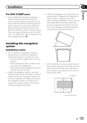
... cm (3-7/8 in a position where the opening of the LCD panel is not securely installed, the current location of the dashboard. - Installation Section 04 English For AVIC-Z120BT users ! Install the navigation unit horizontally on a surface within 0 degrees to 30 degrees tolerance (within 5 degrees to direct sunlight, such as : - Places that the LCD...
... cm (3-7/8 in a position where the opening of the LCD panel is not securely installed, the current location of the dashboard. - Installation Section 04 English For AVIC-Z120BT users ! Install the navigation unit horizontally on a surface within 0 degrees to 30 degrees tolerance (within 5 degrees to direct sunlight, such as : - Places that the LCD...
