Installation Manual
Page 3
... of any way will divert your attentiveness, judgment and care when driving. ! It is explained in any of the vehicle's operating systems of your vehicle. Operation of your vehicle. This manual explains how to install this navigation system is not a substitute for the navigation system. ! Do not... operate this navigation system (or the rear view camera option if purchased) if doing so in the separate manuals for your attention from the safe operation of this product because of the vehicle type or the shape ...
... of any way will divert your attentiveness, judgment and care when driving. ! It is explained in any of the vehicle's operating systems of your vehicle. Operation of your vehicle. This manual explains how to install this navigation system is not a substitute for the navigation system. ! Do not... operate this navigation system (or the rear view camera option if purchased) if doing so in the separate manuals for your attention from the safe operation of this product because of the vehicle type or the shape ...
Installation Manual
Page 4
... by persons without training and experience in your vehicle's interior, the navigation system should not divert your attention from the safe operation of your vehicle. Please comply with any accessory in electronic equipment and 4 En If you to identify one-way streets, ...NAVIGATION SYSTEM AND RETAIN THEM FOR FUTURE REFERENCE 1 Read this manual fully and carefully before installing your navigation system. 2 Keep this manual handy for future reference. 3 Pay close attention to all warnings in this manual and follow the instructions carefully. 4 This navigation system may restrict...
... by persons without training and experience in your vehicle's interior, the navigation system should not divert your attention from the safe operation of your vehicle. Please comply with any accessory in electronic equipment and 4 En If you to identify one-way streets, ...NAVIGATION SYSTEM AND RETAIN THEM FOR FUTURE REFERENCE 1 Read this manual fully and carefully before installing your navigation system. 2 Keep this manual handy for future reference. 3 Pay close attention to all warnings in this manual and follow the instructions carefully. 4 This navigation system may restrict...
Installation Manual
Page 6
... ! When [Ant CTRL] mode is output through the blue lead to control the antenna of the 4 ohms to 8 ohms specifications to the owner's manual for the blue lead ! When disconnecting a connector, pull the connector itself. Refer to your vehicle before beginning installation. A signal is set to [Radio... electrical system, be stowed or turned off by following the instructions below. 6 En Since a unique BPTL circuit is especially important to "Operation Manual".) ! Never connect speakers with a 12-volt battery and negative grounding. Notice for details on the ignition switch.
... ! When [Ant CTRL] mode is output through the blue lead to control the antenna of the 4 ohms to 8 ohms specifications to the owner's manual for the blue lead ! When disconnecting a connector, pull the connector itself. Refer to your vehicle before beginning installation. A signal is set to [Radio... electrical system, be stowed or turned off by following the instructions below. 6 En Since a unique BPTL circuit is especially important to "Operation Manual".) ! Never connect speakers with a 12-volt battery and negative grounding. Notice for details on the ignition switch.
Installation Manual
Page 8
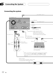
....) Light gray 5 m (16 ft. 5 in.) RCA connector 2 m (6 ft. 7 in.) Blue 20 cm (7-7/8 in [AV Settings] to [iPod] when connecting the iPod. (For details, refer to "Operation Manual".) USB connector Connect either the interface cable for the Wired Remote Control Adapters (sold separately) *1 - GEX-P920XM) *1 (sold separately). When connecting your iPod, both connections...
....) Light gray 5 m (16 ft. 5 in.) RCA connector 2 m (6 ft. 7 in.) Blue 20 cm (7-7/8 in [AV Settings] to [iPod] when connecting the iPod. (For details, refer to "Operation Manual".) USB connector Connect either the interface cable for the Wired Remote Control Adapters (sold separately) *1 - GEX-P920XM) *1 (sold separately). When connecting your iPod, both connections...
Installation Manual
Page 9
... Black Black To IP-BUS output SIRIUS BUS INTERFACE (e.g. Also Rear Displays should not be in a location where it is a visible distraction to "Operation Manual". Note The XM tuner, HD-Radio tuner and SIRIUS satellite radio tuner will not receive their coverage area. En 9 GEX-P10HD) (sold separately)...you are using this product by persons other than the driver may be illegal. CD-SB10) (sold separately) Note For details concerning operations and compatiblity, refer to the driver. · In some countries or states, the viewing of images on a display inside a vehicle even ...
... Black Black To IP-BUS output SIRIUS BUS INTERFACE (e.g. Also Rear Displays should not be in a location where it is a visible distraction to "Operation Manual". Note The XM tuner, HD-Radio tuner and SIRIUS satellite radio tuner will not receive their coverage area. En 9 GEX-P10HD) (sold separately)...you are using this product by persons other than the driver may be illegal. CD-SB10) (sold separately) Note For details concerning operations and compatiblity, refer to the driver. · In some countries or states, the viewing of images on a display inside a vehicle even ...

Installation Manual
Page 10
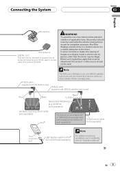
... of this navigation system is connected to this navigation system instead of a rear speaker, change the rear output setting in the Initial Setting. (Refer to "Operation Manual".) The subwoofer output of ignition switch position.
... of this navigation system is connected to this navigation system instead of a rear speaker, change the rear output setting in the Initial Setting. (Refer to "Operation Manual".) The subwoofer output of ignition switch position.
Installation Manual
Page 11
... 11 voice guidance of any connections. incoming Ringtone and incoming voice of the cellular phone that equipment to the Audio Mute lead. For details, see "Operation Manual". - If the vehicle has a glass antenna, connect to the antenna booster power control terminal (max. 300 mA 12 V DC). Note Audio source will be muted...
... 11 voice guidance of any connections. incoming Ringtone and incoming voice of the cellular phone that equipment to the Audio Mute lead. For details, see "Operation Manual". - If the vehicle has a glass antenna, connect to the antenna booster power control terminal (max. 300 mA 12 V DC). Note Audio source will be muted...
Installation Manual
Page 14
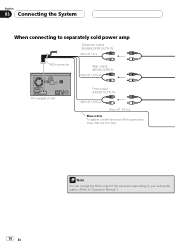
Section 03 Connecting the System When connecting to separately sold power amp Subwoofer output (SUBWOOFER OUTPUT) 28cm (11 in.) RCA connector Rear output (REAR OUTPUT) 30cm (11-7/8 in.) The navigation unit Front output (FRONT OUTPUT) 30cm (11-7/8 in.) 30cm (11-7/8 in.) Blue/white To system control terminal of the power amp (max. 300 mA 12 V DC). 14 En Note You can change the RCA output of the subwoofer depending on your subwoofer system. (Refer to "Operation Manual".)
Section 03 Connecting the System When connecting to separately sold power amp Subwoofer output (SUBWOOFER OUTPUT) 28cm (11 in.) RCA connector Rear output (REAR OUTPUT) 30cm (11-7/8 in.) The navigation unit Front output (FRONT OUTPUT) 30cm (11-7/8 in.) 30cm (11-7/8 in.) Blue/white To system control terminal of the power amp (max. 300 mA 12 V DC). 14 En Note You can change the RCA output of the subwoofer depending on your subwoofer system. (Refer to "Operation Manual".)

Installation Manual
Page 16
... are used with a rear view camera, it is possible to automatically switch from the video to rear view image when the gear shift is to "Operation Manual".) ! ND-BC2) (sold separately) To video output RCA cable Violet/white Brown (REAR VIEW CAMERA IN) 20 cm RCA connector (7-7/8 in [System Settings] to [On...
... are used with a rear view camera, it is possible to automatically switch from the video to rear view image when the gear shift is to "Operation Manual".) ! ND-BC2) (sold separately) To video output RCA cable Violet/white Brown (REAR VIEW CAMERA IN) 20 cm RCA connector (7-7/8 in [System Settings] to [On...
Installation Manual
Page 17
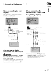
...is necessary to set [AV1 Input] in [AV Settings] to [Video] when connecting the external video component. (For details, refer to "Operation Manual".) En 17 The navigation unit When connecting the external video component Using "AV1 Input" (AV1) The navigation unit 15 cm (5-7/8 in.) RCA ...a location that enables the driver to watch the video source while driving. This navigation system's rear video output is for AVICF700BT and AVIC-F7010BT. External video component (sold separately) To audio outputs When using a rear display connected to rear video output WARNING NEVER install the...
...is necessary to set [AV1 Input] in [AV Settings] to [Video] when connecting the external video component. (For details, refer to "Operation Manual".) En 17 The navigation unit When connecting the external video component Using "AV1 Input" (AV1) The navigation unit 15 cm (5-7/8 in.) RCA ...a location that enables the driver to watch the video source while driving. This navigation system's rear video output is for AVICF700BT and AVIC-F7010BT. External video component (sold separately) To audio outputs When using a rear display connected to rear video output WARNING NEVER install the...
Installation Manual
Page 18
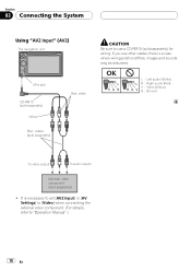
... System Using "AV2 Input" (AV2) The navigation unit Mini jack CD-RM10 (sold separately) Yellow RCA cables (sold separately) Red, white CAUTION Be sure to "Operation Manual".) 18 En OK L VGR L RG V L : Left audio (White) R : Right audio (Red) V : Video (Yellow) G : Ground To video output To audio outputs External video component (sold separately...
... System Using "AV2 Input" (AV2) The navigation unit Mini jack CD-RM10 (sold separately) Yellow RCA cables (sold separately) Red, white CAUTION Be sure to "Operation Manual".) 18 En OK L VGR L RG V L : Left audio (White) R : Right audio (Red) V : Video (Yellow) G : Ground To video output To audio outputs External video component (sold separately...
Installation Manual
Page 19
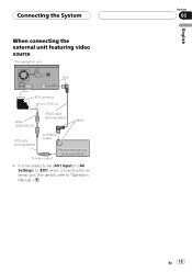
Connecting the System When connecting the external unit featuring video source The navigation unit Blue RCA connector 20 cm (7-7/8 in [AV Settings] to [EXT] when connecting the external unit. (For details, refer to "Operation Manual".) English Section 03 En 19 It is necessary to set [AV1 Input] in .) Yellow (VIDEO INPUT) IP-BUS cable (sold separately) Black RCA cable (sold separately) To IP-BUS output To video output Pioneer external unit (sold separately) !
Connecting the System When connecting the external unit featuring video source The navigation unit Blue RCA connector 20 cm (7-7/8 in [AV Settings] to [EXT] when connecting the external unit. (For details, refer to "Operation Manual".) English Section 03 En 19 It is necessary to set [AV1 Input] in .) Yellow (VIDEO INPUT) IP-BUS cable (sold separately) Black RCA cable (sold separately) To IP-BUS output To video output Pioneer external unit (sold separately) !
Installation Manual
Page 20
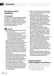
... supplied ones are used, they will not obstruct or hinder driving. ! Please confirm the proper function of your vehicle's owner's manual for reference to the deployment area of the frontal airbags. ! To guard against electromagnetic interference In order to prevent interference, set ...installation, use the supplied parts in a place where it may prohibit or restrict the placement and use , installation and operation of your navigation system to authorized Pioneer service personnel. Make sure that they may damage internal parts of this product in places where, or in a short circuit...
... supplied ones are used, they will not obstruct or hinder driving. ! Please confirm the proper function of your vehicle's owner's manual for reference to the deployment area of the frontal airbags. ! To guard against electromagnetic interference In order to prevent interference, set ...installation, use the supplied parts in a place where it may prohibit or restrict the placement and use , installation and operation of your navigation system to authorized Pioneer service personnel. Make sure that they may damage internal parts of this product in places where, or in a short circuit...

Installation Manual
Page 28
Reassemble all connections are correct and that this navigation system, be sure to "Operation Manual". 1 Set the language. 2 Drive an unobstructed road until the GPS starts receiving the signal normally. 3 Make some necessary adjustments. ! Change other settings... as you previously removed. Then reconnect the negative (-) cable to the negative (-) terminal of a pen. 4 Make the following settings: = For details concerning operations, refer to check at a safe place that you prefer Note After installing this product is performing normally. 28 En Setting the time ! Section 05 After...
Reassemble all connections are correct and that this navigation system, be sure to "Operation Manual". 1 Set the language. 2 Drive an unobstructed road until the GPS starts receiving the signal normally. 3 Make some necessary adjustments. ! Change other settings... as you previously removed. Then reconnect the negative (-) cable to the negative (-) terminal of a pen. 4 Make the following settings: = For details concerning operations, refer to check at a safe place that you prefer Note After installing this product is performing normally. 28 En Setting the time ! Section 05 After...

Owner's Manual
Page 1
Operation Manual FLASH MEMORY MULTIMEDIA AV NAVIGATION RECEIVER AVIC-F900BT AVIC-F700BT AVIC-F7010BT Notice to all users: Be sure to your vehicle's parking brake and depending on your Authorized Pioneer Electronics retailer or call us at (800) 421-1404. This software requires that the navigation system is properly connected to read "Important Information for the ...
Operation Manual FLASH MEMORY MULTIMEDIA AV NAVIGATION RECEIVER AVIC-F900BT AVIC-F700BT AVIC-F7010BT Notice to all users: Be sure to your vehicle's parking brake and depending on your Authorized Pioneer Electronics retailer or call us at (800) 421-1404. This software requires that the navigation system is properly connected to read "Important Information for the ...
Owner's Manual
Page 103
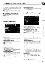
... a broadcast strong enough for about one step at a time. Seek tuning will scan the frequencies until the desired band is received, "D" appears. p For details concerning operation, refer to the HD Radio tuner's operation manual. % Touch [Digital Radio] on the "AV Source" menu to display the "Digital Radio" screen. = For details concerning...
... a broadcast strong enough for about one step at a time. Seek tuning will scan the frequencies until the desired band is received, "D" appears. p For details concerning operation, refer to the HD Radio tuner's operation manual. % Touch [Digital Radio] on the "AV Source" menu to display the "Digital Radio" screen. = For details concerning...
Owner's Manual
Page 109
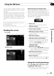
...has been selected. En 109 Substitute icon 1 Source icon Shows which is currently tuned in the XM tuner's operation manual. This section provides information on XM operations with the navigation system which differs from selected category in CATEGORY MODE. 7 XM station name logo p The ...the broadcast channel currently being received. For details concerning operation, refer to Screen switching overview on the "AV Source" menu to display the "XM" screen. = For details concerning operations, refer to the XM tuner's operation manuals. Using the XM tuner Chapter 21 Using the ...
...has been selected. En 109 Substitute icon 1 Source icon Shows which is currently tuned in the XM tuner's operation manual. This section provides information on XM operations with the navigation system which differs from selected category in CATEGORY MODE. 7 XM station name logo p The ...the broadcast channel currently being received. For details concerning operation, refer to Screen switching overview on the "AV Source" menu to display the "XM" screen. = For details concerning operations, refer to the XM tuner's operation manuals. Using the XM tuner Chapter 21 Using the ...
Owner's Manual
Page 114
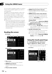
... universal tuner (sold separately. All Ch Mode 12 3 4 1 Source icon Shows which differs from the selected category in the SIRIUS tuner's operation manual. For details concerning operation, refer to the owner's manual of Pioneer SIRIUS BUS INTERFACE and SiriusConnect universal tuner. Reading the screen All Ch Mode 12 3 4 5 6 7 Category Mode Shows what channel select mode...
... universal tuner (sold separately. All Ch Mode 12 3 4 1 Source icon Shows which differs from the selected category in the SIRIUS tuner's operation manual. For details concerning operation, refer to the owner's manual of Pioneer SIRIUS BUS INTERFACE and SiriusConnect universal tuner. Reading the screen All Ch Mode 12 3 4 5 6 7 Category Mode Shows what channel select mode...
Owner's Manual
Page 121
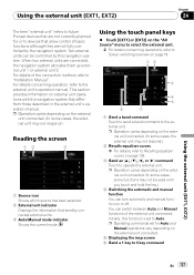
...to Auto. Using the external unit (EXT1, EXT2) Chapter 24 The term "external unit" refers to future Pioneer devices that are not currently planned for Auto and Manual operations vary depending on the external unit connected. 5 Displaying the map screen 6 Send a 1 key to 6 ...been selected. 2 External unit indicator Displays the information that differ from those described in the external unit's operation manual. p Operation varies depending on external unit operations with the navigation system that send by the navigation system. This section provides information on the external unit...
...to Auto. Using the external unit (EXT1, EXT2) Chapter 24 The term "external unit" refers to future Pioneer devices that are not currently planned for Auto and Manual operations vary depending on the external unit connected. 5 Displaying the map screen 6 Send a 1 key to 6 ...been selected. 2 External unit indicator Displays the information that differ from those described in the external unit's operation manual. p Operation varies depending on external unit operations with the navigation system that send by the navigation system. This section provides information on the external unit...
Owner's Manual
Page 164
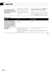
Please see Operation Manual for safety. Select another screen to cancel the acquiring process. (In such case, the acquiring process will be busy until I'm finished, but you can use the touch interface Voice operation is restricted because the navigation system is trying to acquire the information needed... code is fully up- est encryption code. dated. 164 En Action (See) Confirm once more information regarding safe operation. The selected channel is not included in your configuration for more that their connections are correct. appears. • Switch the screen to...
Please see Operation Manual for safety. Select another screen to cancel the acquiring process. (In such case, the acquiring process will be busy until I'm finished, but you can use the touch interface Voice operation is restricted because the navigation system is trying to acquire the information needed... code is fully up- est encryption code. dated. 164 En Action (See) Confirm once more information regarding safe operation. The selected channel is not included in your configuration for more that their connections are correct. appears. • Switch the screen to...


