
WVCU360C User Guide
Page 1
ENGLISH System Controller Operating Instructions Model No. WV-CU360C OPERATE LOGIN ALARM SHIFT ALM RESET VCRALMCRAEMCALL SETUP CAM PROGRAM SETUP ALMFSUUNSCPTEIONND CAAMUFTUONCTION MULTI SCREEN SELECT B/W 1 STILL DEF 2 - SEQ PAUSE EL-ZOOM ...3 6 HOME/PRESET CAMERA BUSY PROHIBITED UNIT A UNIT CLOSE NEAR IRIS FIROICSURSESET OPEN UNIT B AUTO FOCUS FAR WIDE ZOOM L TELE PPRREOSGERTAM DOWN 360 System Controller WV-CU C UP R FRANÇAIS Before attempting to connect or operate this product, please read these instructions carefully and save this manual for future ...
ENGLISH System Controller Operating Instructions Model No. WV-CU360C OPERATE LOGIN ALARM SHIFT ALM RESET VCRALMCRAEMCALL SETUP CAM PROGRAM SETUP ALMFSUUNSCPTEIONND CAAMUFTUONCTION MULTI SCREEN SELECT B/W 1 STILL DEF 2 - SEQ PAUSE EL-ZOOM ...3 6 HOME/PRESET CAMERA BUSY PROHIBITED UNIT A UNIT CLOSE NEAR IRIS FIROICSURSESET OPEN UNIT B AUTO FOCUS FAR WIDE ZOOM L TELE PPRREOSGERTAM DOWN 360 System Controller WV-CU C UP R FRANÇAIS Before attempting to connect or operate this product, please read these instructions carefully and save this manual for future ...
WVCU360C User Guide
Page 5
... Selection PRECAUTIONS • Refer all work related to the installation of the unit you wish to disassemble the appliance. PREFACE The System Controller WV-CU360C is designed for this appliance is 120 V AC 60 Hz by use of the AC Adapter supplied. • Do not use any ...the conventional communication protocol used with care. When the dirt is compatible with the Panasonic Security Data (PS •Data) protocol by default, but DIP switches are provided to operate it is dirty. The controller is hard to qualified service personnel. To prevent electric shock, do not remove screws...
... Selection PRECAUTIONS • Refer all work related to the installation of the unit you wish to disassemble the appliance. PREFACE The System Controller WV-CU360C is designed for this appliance is 120 V AC 60 Hz by use of the AC Adapter supplied. • Do not use any ...the conventional communication protocol used with care. When the dirt is compatible with the Panasonic Security Data (PS •Data) protocol by default, but DIP switches are provided to operate it is dirty. The controller is hard to qualified service personnel. To prevent electric shock, do not remove screws...
WVCU360C User Guide
Page 13
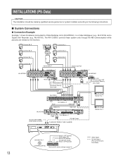
...WV-CU360C controls these system units through RS-485 communication while pictures are viewed on page 15 Monitor No. 1 Monitor No. 2 Video Signal RS-485 Signal (Panasonic Security Data Mode) Refer to four WV-CU360C can be made by qualified service personnel or system installers according to OFF position (for operator mode) Keep in OFF position CONTROLLER...Cable Unit Address 4 POWER ON SIGNAL GND OFF RS-485 Cable 6-conductor Modular Cable (supplied) 901 CONTROLLER No. s System Connections q Connection Example Example 1 shows 8 cameras connected to 2 Data Multiplex Units (WJ-MP204C), ...
...WV-CU360C controls these system units through RS-485 communication while pictures are viewed on page 15 Monitor No. 1 Monitor No. 2 Video Signal RS-485 Signal (Panasonic Security Data Mode) Refer to four WV-CU360C can be made by qualified service personnel or system installers according to OFF position (for operator mode) Keep in OFF position CONTROLLER...Cable Unit Address 4 POWER ON SIGNAL GND OFF RS-485 Cable 6-conductor Modular Cable (supplied) 901 CONTROLLER No. s System Connections q Connection Example Example 1 shows 8 cameras connected to 2 Data Multiplex Units (WJ-MP204C), ...
WVCU360C User Guide
Page 14
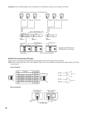
...Connection Data Multiplex Unit WJ-MP204C System Controller WV-CU360C 14 DATA Termination: ON RS-...Controller No. 1 360 System Controller WV-CU UP L R DOWN WV-CU360C Controller No. 2 Controller No. 4 360 System Controller WV-CU UP L R DOWN 360 System Controller WV-CU UP L R DOWN Up to use shielded 4-wire twisted pair cable suitable for MODE switch and CONTROLLER NO. Data Flow Name No. 1 1 - 2 WJ-MP204C ← WV-CU360C GND 1 Controller end TX(B) 2 1 3 WJ-MP204C ← WV-CU360C TX(A) 3 4 WJ-MP204C → WV-CU360C RX(B) 4 6 5 WJ-MP204C → WV-CU360C...
...Connection Data Multiplex Unit WJ-MP204C System Controller WV-CU360C 14 DATA Termination: ON RS-...Controller No. 1 360 System Controller WV-CU UP L R DOWN WV-CU360C Controller No. 2 Controller No. 4 360 System Controller WV-CU UP L R DOWN 360 System Controller WV-CU UP L R DOWN Up to use shielded 4-wire twisted pair cable suitable for MODE switch and CONTROLLER NO. Data Flow Name No. 1 1 - 2 WJ-MP204C ← WV-CU360C GND 1 Controller end TX(B) 2 1 3 WJ-MP204C ← WV-CU360C TX(A) 3 4 WJ-MP204C → WV-CU360C RX(B) 4 6 5 WJ-MP204C → WV-CU360C...

WVCU360C User Guide
Page 15
... the operation mode, Operator or Administrator. • Daisy Chain Connection Video Multiplexer WJ-FS309 (WJ-FS316) Data Multiplex Unit WJ-MP204C System Controller WV-CU360C DATA Termination: ON DATA Termination: OFF Branch Cable RS-485 Cable DATA Termination: ON RS-485 Cable s DIP Switch Setting (PS ... OFF* Operation mode Operator* Line termination Off Reserved Fixed to OFF* System Unit Version Fixed to OFF* System Unit Version Fixed to OFF* System Unit Version Fixed to OFF when the controller is marked with an asterisk *. The default position is located in the...
... the operation mode, Operator or Administrator. • Daisy Chain Connection Video Multiplexer WJ-FS309 (WJ-FS316) Data Multiplex Unit WJ-MP204C System Controller WV-CU360C DATA Termination: ON DATA Termination: OFF Branch Cable RS-485 Cable DATA Termination: ON RS-485 Cable s DIP Switch Setting (PS ... OFF* Operation mode Operator* Line termination Off Reserved Fixed to OFF* System Unit Version Fixed to OFF* System Unit Version Fixed to OFF* System Unit Version Fixed to OFF when the controller is marked with an asterisk *. The default position is located in the...

WVCU360C User Guide
Page 16
... ON 12 3 4 56 78 Bit 3 should be set to ON when it is used . 16 Remove the DC plug from the rear of the WV-CU360C controller in a PS •Data system. 1. Controller No. One controller within the multiple controller system must be assigned the number 1. • Positions #0 and #9 are reserved and cannot be set prior to operating...
... ON 12 3 4 56 78 Bit 3 should be set to ON when it is used . 16 Remove the DC plug from the rear of the WV-CU360C controller in a PS •Data system. 1. Controller No. One controller within the multiple controller system must be assigned the number 1. • Positions #0 and #9 are reserved and cannot be set prior to operating...

WVCU360C User Guide
Page 17
... the following before entering the setup mode. 1. With the power turned off , move bit #6 of the MODE switch on the power of the joystick. The controller is completed, restore the switch to ON (administrator) position. 3. With the power turned off , move bit #6 of the MODE switch on the LED display, set... menu UP R or DOWN UP L R or DOWN STILL Left: To decrease the parameter - Confirm that all necessary connections and switch settings are used for the WV-CU360C System Controller on the rear to its original position. 1. EL-ZOOM Right: To increase the parameter + 17
... the following before entering the setup mode. 1. With the power turned off , move bit #6 of the MODE switch on the power of the joystick. The controller is completed, restore the switch to ON (administrator) position. 3. With the power turned off , move bit #6 of the MODE switch on the LED display, set... menu UP R or DOWN UP L R or DOWN STILL Left: To decrease the parameter - Confirm that all necessary connections and switch settings are used for the WV-CU360C System Controller on the rear to its original position. 1. EL-ZOOM Right: To increase the parameter + 17

WVCU360C User Guide
Page 31
.../ PUSH- PAUSE SET / / REW/FF PPrreesss s / JJooggDDiaial l WV-CU360C HolHdolddodwownn 2 s2ecseocnodnsds UP SETUP FUNCTION L R L R UP R DOWN UP L R DOWN MON DOWN Note Button lock is controlled from the System Controller using shortcuts assigned to the manual included with the digital disk recorder. Item ...Selected Alarm Record Recording Stop Stop Playback Stop Recording Playback Pause Step Playback FWD. s Digital Disk Recorder Control A Digital Disk Recorder is released automatically by opening the setup menu. The operating procedures on the following pages ...
.../ PUSH- PAUSE SET / / REW/FF PPrreesss s / JJooggDDiaial l WV-CU360C HolHdolddodwownn 2 s2ecseocnodnsds UP SETUP FUNCTION L R L R UP R DOWN UP L R DOWN MON DOWN Note Button lock is controlled from the System Controller using shortcuts assigned to the manual included with the digital disk recorder. Item ...Selected Alarm Record Recording Stop Stop Playback Stop Recording Playback Pause Step Playback FWD. s Digital Disk Recorder Control A Digital Disk Recorder is released automatically by opening the setup menu. The operating procedures on the following pages ...

WVCU360C User Guide
Page 32
... Lock OFF Button Lock ON Daylight Savings ON/OFF Timer Mode Selection Record List Display ON/OFF Record Search Window ON Controller Operation SETUP SHIFT FUNCTION SETUP SHIFT FUNCTION SETUP SHIFT FUNCTION SETUP SHIFT FUNCTION SETUP SHIFT FUNCTION SETUP SHIFT FUNCTION SETUP SHIFT ...more details, refer to stop playback Exclusive use to the Operating Instructions included with the digital disk recorder. SHIFT SHIFT SHIFT SHIFT WV-CU360C 13 30 31 SETUP Note FUNCTION SETUP FUNCTION SETUP OFF, INT or EXT selectable FUNCTION SETUP FUNCTION q WJ-HD500A Shortcuts The ...
... Lock OFF Button Lock ON Daylight Savings ON/OFF Timer Mode Selection Record List Display ON/OFF Record Search Window ON Controller Operation SETUP SHIFT FUNCTION SETUP SHIFT FUNCTION SETUP SHIFT FUNCTION SETUP SHIFT FUNCTION SETUP SHIFT FUNCTION SETUP SHIFT FUNCTION SETUP SHIFT ...more details, refer to stop playback Exclusive use to the Operating Instructions included with the digital disk recorder. SHIFT SHIFT SHIFT SHIFT WV-CU360C 13 30 31 SETUP Note FUNCTION SETUP FUNCTION SETUP OFF, INT or EXT selectable FUNCTION SETUP FUNCTION q WJ-HD500A Shortcuts The ...

WVCU360C User Guide
Page 34
...Alarm reset operations including auto reset are applied to all system units, not to a selected one. • Alarm reset mode differs depending on the system unit connected to the WV-CU360C. • Confirm that the SHIFT button is applied to all system units, not to steady light when the alarm is ... Record Display Controller Operation SETUP SHIFT FUNCTION SETUP SHIFT FUNCTION SETUP SHIFT FUNCTION Note Equal to be disturbed by alarm input as for example during setup operations. 1. Use this function when you do not want to EL-ZOOM s Alarm Operation When the WV-CU360C receives an ...
...Alarm reset operations including auto reset are applied to all system units, not to a selected one. • Alarm reset mode differs depending on the system unit connected to the WV-CU360C. • Confirm that the SHIFT button is applied to all system units, not to steady light when the alarm is ... Record Display Controller Operation SETUP SHIFT FUNCTION SETUP SHIFT FUNCTION SETUP SHIFT FUNCTION Note Equal to be disturbed by alarm input as for example during setup operations. 1. Use this function when you do not want to EL-ZOOM s Alarm Operation When the WV-CU360C receives an ...
WVCU360C User Guide
Page 42
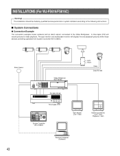
... connected to the following instructions. A time lapse VCR will display live and playback pictures while these devices are being operated from System Controller WV-CU360C. Alarm Sensor LOCK POWER ON OFF ALARM MULTI MULTISCREEN SCREEN SELECT 1 CAMERA/PRESET POSITION 2 3 4 RESET SPOT SEQUENCE 5 ...ON/OFF UNIT ESC CAM SET 360 System Controller WV-CU C For Multiplexer CAMERA SITE CONTROL IRIS CLOSE OPEN IRIS RESET UP AUTO/+ FOCUS NEAR FAR AUX 2 L R HOME/TELE AUX 1 ZOOM WIDE DOWN AUTO FOCUS System Controller WV-CU360C Spot Monitor Live 1-16ch Multiscreen Monitor ...
... connected to the following instructions. A time lapse VCR will display live and playback pictures while these devices are being operated from System Controller WV-CU360C. Alarm Sensor LOCK POWER ON OFF ALARM MULTI MULTISCREEN SCREEN SELECT 1 CAMERA/PRESET POSITION 2 3 4 RESET SPOT SEQUENCE 5 ...ON/OFF UNIT ESC CAM SET 360 System Controller WV-CU C For Multiplexer CAMERA SITE CONTROL IRIS CLOSE OPEN IRIS RESET UP AUTO/+ FOCUS NEAR FAR AUX 2 L R HOME/TELE AUX 1 ZOOM WIDE DOWN AUTO FOCUS System Controller WV-CU360C Spot Monitor Live 1-16ch Multiscreen Monitor ...
WVCU360C User Guide
Page 43
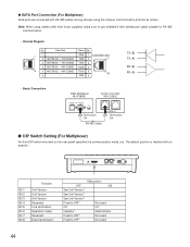
.... GND 6 TX (B) TX (A) RX (B) RX (A) • Basic Connection Video Multiplexer WJ-FS616C System Controller WV-CU360C DATA OUT IN TERM. Data Flow Name No. 1 1 - 2 WJ-FS616C ← WV-CU360C GND 1 Controller end TX(B) 2 1 3 WJ-FS616C ← WV-CU360C TX(A) 3 4 WJ-FS616C → WV-CU360C RX(B) 4 6 5 WJ-FS616C → WV-CU360C RX(A) 5 6 6 - q DATA Port Connection (For Multiplexer) Data ports are connected with an asterisk...
.... GND 6 TX (B) TX (A) RX (B) RX (A) • Basic Connection Video Multiplexer WJ-FS616C System Controller WV-CU360C DATA OUT IN TERM. Data Flow Name No. 1 1 - 2 WJ-FS616C ← WV-CU360C GND 1 Controller end TX(B) 2 1 3 WJ-FS616C ← WV-CU360C TX(A) 3 4 WJ-FS616C → WV-CU360C RX(B) 4 6 5 WJ-FS616C → WV-CU360C RX(A) 5 6 6 - q DATA Port Connection (For Multiplexer) Data ports are connected with an asterisk...

WVCU360C User Guide
Page 45
...off , move bit #6 of the MODE switch on the rear to the controller. 4. Supply power to ON (administrator) position. 3. SETUP PROCEDURES (For WJ-FS616/FS616C) To display the setup menus for the WV-CU360C System Controller on the rear to enter the setup mode. Supply power to its original ...#6 of cameras and other system units. 5. Turn on the power of the MODE switch on the LED display, set the MODE switch and power up the controller as described below. The controller is completed, restore the switch to the controller. s Buttons and Controls used for Setup The following...
...off , move bit #6 of the MODE switch on the rear to the controller. 4. Supply power to ON (administrator) position. 3. SETUP PROCEDURES (For WJ-FS616/FS616C) To display the setup menus for the WV-CU360C System Controller on the rear to enter the setup mode. Supply power to its original ...#6 of cameras and other system units. 5. Turn on the power of the MODE switch on the LED display, set the MODE switch and power up the controller as described below. The controller is completed, restore the switch to the controller. s Buttons and Controls used for Setup The following...

WVCU360C User Guide
Page 49
s Alarm Operation When the WV-CU360C receives an alarm signal from blinking to steady light when the alarm is reset and the alarm indicator on the controller goes off . Press the ALM RESET button while the ALT indicator is in operation. Press the ALM SUSPEND button for more than 2 ... Multiplexer from 24H mode to reset alarm suspension. The ALM SUSPEND indicator goes off . q Alarm Reset 1. ALM RESET ALL RESET 2. s VTR (VCR) Control You can operate a VTR (VCR) connected to suspend the alarm. Press the ALM RESET button to 72H mode q Alarm Suspension 1. An activated alarm is ...
s Alarm Operation When the WV-CU360C receives an alarm signal from blinking to steady light when the alarm is reset and the alarm indicator on the controller goes off . Press the ALM RESET button while the ALT indicator is in operation. Press the ALM SUSPEND button for more than 2 ... Multiplexer from 24H mode to reset alarm suspension. The ALM SUSPEND indicator goes off . q Alarm Reset 1. ALM RESET ALL RESET 2. s VTR (VCR) Control You can operate a VTR (VCR) connected to suspend the alarm. Press the ALM RESET button to 72H mode q Alarm Suspension 1. An activated alarm is ...

WVCU360C User Guide
Page 56
...WV-CU360C GND 1 Controller end TX(B) 2 1 3 WJ-SX350 ← WV-CU360C TX(A) 3 4 WJ-SX350 → WV-CU360C RX(B) 4 6 5 WJ-SX350 → WV-CU360C RX(A) 5 6 6 - GND 6 • Basic Connection DATA IN 4 3 2 1 TX (B) TX (A) RX (B) RX (A) Matrix Switcher WJ-SX350 POWER LOCK ALARM MONITOR CAMERA BUSY PROHIBITED 123 456 789 0 CAMERA SITE CONTROL... 9V IN Bit 1 Bit 2 Bit 3 Bit 4 Bit 5 Bit 6 Bit 7 Bit 8 Function System Unit Version System Unit Version System Unit Version Reserved Line termination Operation mode Baud Rate Selection Repeat Transmissions OFF * * * * Off Operator*...
...WV-CU360C GND 1 Controller end TX(B) 2 1 3 WJ-SX350 ← WV-CU360C TX(A) 3 4 WJ-SX350 → WV-CU360C RX(B) 4 6 5 WJ-SX350 → WV-CU360C RX(A) 5 6 6 - GND 6 • Basic Connection DATA IN 4 3 2 1 TX (B) TX (A) RX (B) RX (A) Matrix Switcher WJ-SX350 POWER LOCK ALARM MONITOR CAMERA BUSY PROHIBITED 123 456 789 0 CAMERA SITE CONTROL... 9V IN Bit 1 Bit 2 Bit 3 Bit 4 Bit 5 Bit 6 Bit 7 Bit 8 Function System Unit Version System Unit Version System Unit Version Reserved Line termination Operation mode Baud Rate Selection Repeat Transmissions OFF * * * * Off Operator*...

WVCU360C User Guide
Page 58
...displays [SEtUP]. Confirm that all necessary connections and switch settings are used for the WV-CU360C System Controller on the rear to ON (administrator) position. 3. Supply power to enter the setup mode. The controller is completed, restore the switch to its original position. 1. Supply power to Setup... Do the following buttons and joystick operations are complete. 2. s Prior to the controller. 60 With the power turned off , move bit #6 of cameras and other system units. 5. Turn on the power of the MODE switch on the rear to OFF (operator) position...
...displays [SEtUP]. Confirm that all necessary connections and switch settings are used for the WV-CU360C System Controller on the rear to ON (administrator) position. 3. Supply power to enter the setup mode. The controller is completed, restore the switch to its original position. 1. Supply power to Setup... Do the following buttons and joystick operations are complete. 2. s Prior to the controller. 60 With the power turned off , move bit #6 of cameras and other system units. 5. Turn on the power of the MODE switch on the rear to OFF (operator) position...
WVCU360C User Guide
Page 68
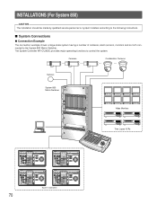
... PRESET ZOOM WIDE TELE CAMERA (ENTER) DOWN AUTO PAN System Controllers Time Lapse VCRs 850 System Controller WU-CU INSTALLATIONS (For System 850) CAUTION The installation should be made by qualified service personnel or system installers according to control the system. The System Controller WV-CU360C provides major operating functions to the following instructions. s System Connections q Connection Example The connection example shows a large...
... PRESET ZOOM WIDE TELE CAMERA (ENTER) DOWN AUTO PAN System Controllers Time Lapse VCRs 850 System Controller WU-CU INSTALLATIONS (For System 850) CAUTION The installation should be made by qualified service personnel or system installers according to control the system. The System Controller WV-CU360C provides major operating functions to the following instructions. s System Connections q Connection Example The connection example shows a large...

WVCU360C User Guide
Page 69
... INTERFACE (RS-232C) 3 2 1 SYSTEM CONTROLLER (RS-485) DATA 6 DATA 5 DATA 4 DATA 3 DATA 2 DATA 1 REDUNDANT SATELLITE CPU MODE PARALLEL NO YES STANDALONE SATELLITE Main CPU Central Processing Unit SIGNAL GND 125V 3.0A AC IN 71 Data Flow 1 - 1 2 Main CPU ← WV-CU360C 3 Main CPU ← WV-CU360C 4 Main CPU → WV-CU360C 6 5 Main CPU → WV-CU360C 6 - MODE DATA DC 9V...
... INTERFACE (RS-232C) 3 2 1 SYSTEM CONTROLLER (RS-485) DATA 6 DATA 5 DATA 4 DATA 3 DATA 2 DATA 1 REDUNDANT SATELLITE CPU MODE PARALLEL NO YES STANDALONE SATELLITE Main CPU Central Processing Unit SIGNAL GND 125V 3.0A AC IN 71 Data Flow 1 - 1 2 Main CPU ← WV-CU360C 3 Main CPU ← WV-CU360C 4 Main CPU → WV-CU360C 6 5 Main CPU → WV-CU360C 6 - MODE DATA DC 9V...

WVCU360C User Guide
Page 71
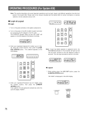
With the power turned off , move bit #6 of cameras and other system units. 5. SETUP PROCEDURES (For System 850) To display the setup menus for the WV-CU360C System Controller on the rear to ON (administrator) position. 3. Confirm that all necessary connections and switch settings are used for setup. 0 9 Numeric buttons: To select a ... setup mode. Turn on the power of the MODE switch on the LED display, set the MODE switch and power up the controller as described below. Operator mode OFF ON 1 234 5678 MODE OFF ON 1 234 5678 MODE Administrator mode DC 9V IN s Buttons and...
With the power turned off , move bit #6 of cameras and other system units. 5. SETUP PROCEDURES (For System 850) To display the setup menus for the WV-CU360C System Controller on the rear to ON (administrator) position. 3. Confirm that all necessary connections and switch settings are used for setup. 0 9 Numeric buttons: To select a ... setup mode. Turn on the power of the MODE switch on the LED display, set the MODE switch and power up the controller as described below. Operator mode OFF ON 1 234 5678 MODE OFF ON 1 234 5678 MODE Administrator mode DC 9V IN s Buttons and...
WVCU360C User Guide
Page 73
...as login, logout, and different operations from the front panel of the WV-CU360C System Controller by connecting the AC adapter to the AC outlet. Turn on the LED display for further information on the power switches of the System Controller. 3. If the operator ID and password entered are valid, the LED... will blink on the power of the System 850. "NO USER" is displayed on the LED display. The underline appears on...
...as login, logout, and different operations from the front panel of the WV-CU360C System Controller by connecting the AC adapter to the AC outlet. Turn on the LED display for further information on the power switches of the System Controller. 3. If the operator ID and password entered are valid, the LED... will blink on the power of the System 850. "NO USER" is displayed on the LED display. The underline appears on...


