
WVCU360C User Guide
Page 1
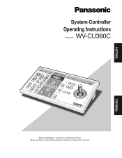
... PROHIBITED UNIT A UNIT CLOSE NEAR IRIS FIROICSURSESET OPEN UNIT B AUTO FOCUS FAR WIDE ZOOM L TELE PPRREOSGERTAM DOWN 360 System Controller WV-CU C UP R FRANÇAIS Before attempting to connect or operate this product, please read these instructions carefully... and save this manual for future use. ENGLISH System Controller Operating Instructions Model No. WV-CU360C OPERATE LOGIN ALARM SHIFT ALM RESET VCRALMCRAEMCALL SETUP CAM PROGRAM SETUP ALMFSUUNSCPTEIONND CAAMUFTUONCTION MULTI SCREEN...
... PROHIBITED UNIT A UNIT CLOSE NEAR IRIS FIROICSURSESET OPEN UNIT B AUTO FOCUS FAR WIDE ZOOM L TELE PPRREOSGERTAM DOWN 360 System Controller WV-CU C UP R FRANÇAIS Before attempting to connect or operate this product, please read these instructions carefully... and save this manual for future use. ENGLISH System Controller Operating Instructions Model No. WV-CU360C OPERATE LOGIN ALARM SHIFT ALM RESET VCRALMCRAEMCALL SETUP CAM PROGRAM SETUP ALMFSUUNSCPTEIONND CAAMUFTUONCTION MULTI SCREEN...

WVCU360C User Guide
Page 4
... Panel Switch Setting (Summary 8 Chapter 1 For Panasonic Security Data (PS •Data) Systems ........ 9 MAJOR OPERATING CONTROLS & THEIR FUNCTIONS .... 10 s Front View (Template for PS •Data 10 INSTALLATIONS (PS •Data 13 s System Connections 13 s DIP Switch Setting (PS •Data 15 s Controller Number Setting (PS •Data 16 CONTROLLER SETUP PROCEDURES (PS •Data 17...
... Panel Switch Setting (Summary 8 Chapter 1 For Panasonic Security Data (PS •Data) Systems ........ 9 MAJOR OPERATING CONTROLS & THEIR FUNCTIONS .... 10 s Front View (Template for PS •Data 10 INSTALLATIONS (PS •Data 13 s System Connections 13 s DIP Switch Setting (PS •Data 15 s Controller Number Setting (PS •Data 16 CONTROLLER SETUP PROCEDURES (PS •Data 17...
WVCU360C User Guide
Page 5
... • Monitor Selection • Alarm (Display/Suspend/Recall/Reset) • Camera and system unit setup Camera controls • Lens functions: Iris/Focus/Auto Focus/Zoom • Housing: Defroster/Wiper/Auxiliary ...Panasonic Security Data (PS •Data) protocol by selecting cameras and monitors, watching monitor screens and indicators, and controlling pan/tilt, lens and other than the one supplied. Do not strike or shake, as this product to qualified service personnel or system installers. • Do not attempt to qualified service personnel. PREFACE The System Controller...
... • Monitor Selection • Alarm (Display/Suspend/Recall/Reset) • Camera and system unit setup Camera controls • Lens functions: Iris/Focus/Auto Focus/Zoom • Housing: Defroster/Wiper/Auxiliary ...Panasonic Security Data (PS •Data) protocol by selecting cameras and monitors, watching monitor screens and indicators, and controlling pan/tilt, lens and other than the one supplied. Do not strike or shake, as this product to qualified service personnel or system installers. • Do not attempt to qualified service personnel. PREFACE The System Controller...

WVCU360C User Guide
Page 6
...supplied AC adapter to feed DC 9 V to the AC adapter. DO NOT OPEN RISQUE DE CHOCS ELECTROUES NE PAS OUVRIR 78 456 23 901 CONTROLLER No. A system may comprise up to set communication parameters for the DC plug of the supplied AC adapter. r DC 9 V Input Jack (DC 9V IN...) Jack for the System Controller. e Data Ports (DATA) These ports are used to assign a controller number to the System Controller to exchange control data with the connected system units via the supplied RS-485 cable. The new settings will take effect when the power...
...supplied AC adapter to feed DC 9 V to the AC adapter. DO NOT OPEN RISQUE DE CHOCS ELECTROUES NE PAS OUVRIR 78 456 23 901 CONTROLLER No. A system may comprise up to set communication parameters for the DC plug of the supplied AC adapter. r DC 9 V Input Jack (DC 9V IN...) Jack for the System Controller. e Data Ports (DATA) These ports are used to assign a controller number to the System Controller to exchange control data with the connected system units via the supplied RS-485 cable. The new settings will take effect when the power...

WVCU360C User Guide
Page 7
...DEF ON CLEAR F2 OSD MONITOR (ESC) CAM FUNC LOCK OSD SERVICE SHIFT BLK EXIT 360 BUSY PROHIBITED System Controller WV-CU C For Matrix Switcher (System 850) CAMERA SITE CONTROL IRIS CLOSE OPEN IRIS RESET UP PROGRAM PRESET FOCUS NEAR FAR AUTO FOCUS L R CALL PRESET ZOOM ...WIDE TELE CAMERA (ENTER) DOWN AUTO PAN 7 SEQ PAUSE + SEQUENCE AUX 1 PATROL PLAY MON CAMERA 360 BUSY PROHIBITED System Controller WV-CU C IRIS CLOSE OPEN IRIS RESET UP UNIT A FOCUS NEAR FAR UNIT AUTO FOCUS L R UNIT B WIDE ZOOM TELE CAM HOME/...
...DEF ON CLEAR F2 OSD MONITOR (ESC) CAM FUNC LOCK OSD SERVICE SHIFT BLK EXIT 360 BUSY PROHIBITED System Controller WV-CU C For Matrix Switcher (System 850) CAMERA SITE CONTROL IRIS CLOSE OPEN IRIS RESET UP PROGRAM PRESET FOCUS NEAR FAR AUTO FOCUS L R CALL PRESET ZOOM ...WIDE TELE CAMERA (ENTER) DOWN AUTO PAN 7 SEQ PAUSE + SEQUENCE AUX 1 PATROL PLAY MON CAMERA 360 BUSY PROHIBITED System Controller WV-CU C IRIS CLOSE OPEN IRIS RESET UP UNIT A FOCUS NEAR FAR UNIT AUTO FOCUS L R UNIT B WIDE ZOOM TELE CAM HOME/...

WVCU360C User Guide
Page 8
... (Summary) An 8-bit DIP switch and a rotary switch mounted on your system configuration such as a PS •Data system, WJ-FS616C Multiplexer system, WJ-SX350 Matrix Switcher system or System 850. System PS•Data 78 23 Controller No. Switch settings depend on the rear of switch settings provided for communication.... WJ-SX350 (Ver. 6.00 or later) WJ-SX350 (Ver. 1.xx) 78 78 78 901 #1 CONTROLLER No. 901 #1 CONTROLLER No. 901 #1 CONTROLLER No. 23 23 23 System 850 WJ-SX850 78 901 #1 CONTROLLER No. 23 MODE DIP SW OFF ON 1 234 5678 MODE OFF ON 1 234 5678 MODE OFF ON...
... (Summary) An 8-bit DIP switch and a rotary switch mounted on your system configuration such as a PS •Data system, WJ-FS616C Multiplexer system, WJ-SX350 Matrix Switcher system or System 850. System PS•Data 78 23 Controller No. Switch settings depend on the rear of switch settings provided for communication.... WJ-SX350 (Ver. 6.00 or later) WJ-SX350 (Ver. 1.xx) 78 78 78 901 #1 CONTROLLER No. 901 #1 CONTROLLER No. 901 #1 CONTROLLER No. 23 23 23 System 850 WJ-SX850 78 901 #1 CONTROLLER No. 23 MODE DIP SW OFF ON 1 234 5678 MODE OFF ON 1 234 5678 MODE OFF ON...
WVCU360C User Guide
Page 10
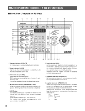
... level. The monitor or unit number is displayed when initial communication is prohibited to the System Controller. i Joystick Controller (UP/DOWN/L/R) Used to control a system unit or camera that is established. MAJOR OPERATING CONTROLS & THEIR FUNCTIONS s Front View (Template for PS•Data) qwe rt yu i...changes to confirm the monitor or unit number and the number of the currently controlled camera. When it goes off , press the Alarm Reset button. Operations from the System Controller are currently operating. Holding down the joystick in the desired position will keep ...
... level. The monitor or unit number is displayed when initial communication is prohibited to the System Controller. i Joystick Controller (UP/DOWN/L/R) Used to control a system unit or camera that is established. MAJOR OPERATING CONTROLS & THEIR FUNCTIONS s Front View (Template for PS•Data) qwe rt yu i...changes to confirm the monitor or unit number and the number of the currently controlled camera. When it goes off , press the Alarm Reset button. Operations from the System Controller are currently operating. Holding down the joystick in the desired position will keep ...

WVCU360C User Guide
Page 12
... shift mode will turn on the monitor screen. The LED next to the cameras or the system. The LED next to display the alarm logs on the AUX 1 function controlling accessories connected to the button is lit while Electronic Zoom mode is active. Pressing this button ... while VCR is selected. Pressing this button in the shift mode will move the camera sequence one step forward from the step previously paused while a system unit (e.g., a Video Multiplexer) provided with SEQ PAUSE (e.g., a Video Multiplexer) is lit while the defroster or AUX 2 function operates. @3 Wiper/Auxiliary 1 ...
... shift mode will turn on the monitor screen. The LED next to the cameras or the system. The LED next to display the alarm logs on the AUX 1 function controlling accessories connected to the button is lit while Electronic Zoom mode is active. Pressing this button ... while VCR is selected. Pressing this button in the shift mode will move the camera sequence one step forward from the step previously paused while a system unit (e.g., a Video Multiplexer) provided with SEQ PAUSE (e.g., a Video Multiplexer) is lit while the defroster or AUX 2 function operates. @3 Wiper/Auxiliary 1 ...
WVCU360C User Guide
Page 13
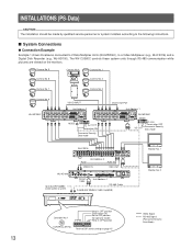
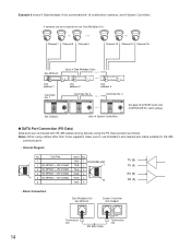
... The installation should be used in OFF position CONTROLLER No. The WV-CU360C controls these system units through RS-485 communication while pictures are viewed on page 15 Monitor No. 1 Monitor No. 2 Video Signal RS-485 Signal (Panasonic Security Data Mode) Refer to the following instructions...DIP switch setting on the monitors. s System Connections q Connection Example Example 1 shows 8 cameras connected to 2 Data Multiplex Units (WJ-MP204C), to OFF position (for operator mode) Keep in a system. MODE DATA DC 9V IN 456 456 23 23 Controller No. 1 901 Keep in OFF ...
... The installation should be used in OFF position CONTROLLER No. The WV-CU360C controls these system units through RS-485 communication while pictures are viewed on page 15 Monitor No. 1 Monitor No. 2 Video Signal RS-485 Signal (Panasonic Security Data Mode) Refer to the following instructions...DIP switch setting on the monitors. s System Connections q Connection Example Example 1 shows 8 cameras connected to 2 Data Multiplex Units (WJ-MP204C), to OFF position (for operator mode) Keep in a system. MODE DATA DC 9V IN 456 456 23 23 Controller No. 1 901 Keep in OFF ...
WVCU360C User Guide
Page 14
... 2 shows 4 Data Multiplex Units connected with RS-485 cables among devices using cables other than those supplied, make sure to 4 System Controllers See page 16 for RS-485 communication. • Internal Diagram No. q DATA Port Connection (PS •Data) Data ports are...2 Data Multiplex Unit WJ-MP204 Unit address 4 Data Multiplex Unit WJ-MP204 Controller No. 1 360 System Controller WV-CU UP L R DOWN WV-CU360C Controller No. 2 Controller No. 4 360 System Controller WV-CU UP L R DOWN 360 System Controller WV-CU UP L R DOWN Up to use shielded 4-wire twisted pair cable...
... 2 shows 4 Data Multiplex Units connected with RS-485 cables among devices using cables other than those supplied, make sure to 4 System Controllers See page 16 for RS-485 communication. • Internal Diagram No. q DATA Port Connection (PS •Data) Data ports are...2 Data Multiplex Unit WJ-MP204 Unit address 4 Data Multiplex Unit WJ-MP204 Controller No. 1 360 System Controller WV-CU UP L R DOWN WV-CU360C Controller No. 2 Controller No. 4 360 System Controller WV-CU UP L R DOWN 360 System Controller WV-CU UP L R DOWN Up to use shielded 4-wire twisted pair cable...

WVCU360C User Guide
Page 15
...5 opens or terminates the communication chain. • Daisy Chain Connection Video Multiplexer WJ-FS309 (WJ-FS316) Data Multiplex Unit WJ-MP204C System Controller WV-CU360C DATA Termination: ON DATA Termination: OFF Branch Cable RS-485 Cable DATA Termination: ON RS-485 Cable s DIP Switch Setting...OFF* Operation mode Operator* Line termination Off Reserved Fixed to OFF* System Unit Version Fixed to OFF* System Unit Version Fixed to OFF* System Unit Version Fixed to Administrator when setting up the controller. The default position is located in the OFF position. 15
...5 opens or terminates the communication chain. • Daisy Chain Connection Video Multiplexer WJ-FS309 (WJ-FS316) Data Multiplex Unit WJ-MP204C System Controller WV-CU360C DATA Termination: ON DATA Termination: OFF Branch Cable RS-485 Cable DATA Termination: ON RS-485 Cable s DIP Switch Setting...OFF* Operation mode Operator* Line termination Off Reserved Fixed to OFF* System Unit Version Fixed to OFF* System Unit Version Fixed to OFF* System Unit Version Fixed to Administrator when setting up the controller. The default position is located in the OFF position. 15

WVCU360C User Guide
Page 16
...plug to the number you wish. 901 78 23 456 CONTROLLER No. 3. OFF ON 12 3 4 56 78 Bit 3 should be set prior to operating a system connected as shown in Example 2. One controller within the multiple controller system must be assigned the number 1. • Positions #0 and... #9 are reserved and cannot be set to OFF. s Controller Number Setting (PS •Data) A 10-position rotary ...
...plug to the number you wish. 901 78 23 456 CONTROLLER No. 3. OFF ON 12 3 4 56 78 Bit 3 should be set prior to operating a system connected as shown in Example 2. One controller within the multiple controller system must be assigned the number 1. • Positions #0 and... #9 are reserved and cannot be set to OFF. s Controller Number Setting (PS •Data) A 10-position rotary ...

WVCU360C User Guide
Page 17
... With the power turned off , move bit #6 of cameras and other system units. 5. The controller is completed, restore the switch to Setup Do the following before entering the setup mode. 1. s Buttons and Controls used for the WV-CU360C System Controller on the rear to the previous menu L R DOWN UP L R...the selection by use of operating the joystick, you can enter the number enclosed in the setup operation. Instead of the joystick. CONTROLLER SETUP PROCEDURES (PS•Data) To display the setup menus for Setup The following buttons and joystick operations are complete. 2. ...
... With the power turned off , move bit #6 of cameras and other system units. 5. The controller is completed, restore the switch to Setup Do the following before entering the setup mode. 1. s Buttons and Controls used for the WV-CU360C System Controller on the rear to the previous menu L R DOWN UP L R...the selection by use of operating the joystick, you can enter the number enclosed in the setup operation. Instead of the joystick. CONTROLLER SETUP PROCEDURES (PS•Data) To display the setup menus for Setup The following buttons and joystick operations are complete. 2. ...

WVCU360C User Guide
Page 18
..., press (12345*) SET (1) 2 400 (2) 4 800 (3) 9 600* (4) 19 200 Move Joystick up and down to select L R DOWN UP L R Parity Parity Check Wait Wait Time (ms) Controller Unit Group System Unit Group Unit A Number Unit B Number Unit Assignment to Button A Unit Assignment to Button B User Password Super User Password Administrator Password User User Certification...
..., press (12345*) SET (1) 2 400 (2) 4 800 (3) 9 600* (4) 19 200 Move Joystick up and down to select L R DOWN UP L R Parity Parity Check Wait Wait Time (ms) Controller Unit Group System Unit Group Unit A Number Unit B Number Unit Assignment to Button A Unit Assignment to Button B User Password Super User Password Administrator Password User User Certification...
WVCU360C User Guide
Page 19
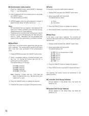
... that you register a new password different from "12345" in [SUSrP], and note down the registered password for future reference. • Powering up the controller while holding down numeric buttons 2, 4 and 5 simultaneously will reset the password to "12345". Select a parameter entering a bracket-enclosed number, e.g., (3), moving...the Setup menu, but leave the default as it is. Press the ESC button to go back to validate the selection. 4. q System Unit-Group Address [SU-gr] appears on the Setup menu, but leave the default as it is no retransmission of the other menu...
... that you register a new password different from "12345" in [SUSrP], and note down the registered password for future reference. • Powering up the controller while holding down numeric buttons 2, 4 and 5 simultaneously will reset the password to "12345". Select a parameter entering a bracket-enclosed number, e.g., (3), moving...the Setup menu, but leave the default as it is. Press the ESC button to go back to validate the selection. 4. q System Unit-Group Address [SU-gr] appears on the Setup menu, but leave the default as it is no retransmission of the other menu...

WVCU360C User Guide
Page 20
...A7-07 A8-08 A9-09 2. q Administrator Password In this menu, a 5-digit password for example. Enter a 5-digit password with the joystick controller. The default setting is enabled or disabled. 1. Press the ESC button to go back to A9, "A numbers", stand for use in the ...button Assignment In this menu, a maximum of unit address. Press the ESC button to go back to numeric buttons 1-9 regardless of 9 system units is shown below. A frequently used system unit can occur in normal operation. Display [UsrP ] and press the CAM/SET button. The first 2 digits from 1 to UNIT...
...A7-07 A8-08 A9-09 2. q Administrator Password In this menu, a 5-digit password for example. Enter a 5-digit password with the joystick controller. The default setting is enabled or disabled. 1. Press the ESC button to go back to A9, "A numbers", stand for use in the ...button Assignment In this menu, a maximum of unit address. Press the ESC button to go back to numeric buttons 1-9 regardless of 9 system units is shown below. A frequently used system unit can occur in normal operation. Display [UsrP ] and press the CAM/SET button. The first 2 digits from 1 to UNIT...

WVCU360C User Guide
Page 22
...operation starts with a log-out procedure. SYSTEM OPERATION • Alarm Reset • Alarm Suspend • Alarm Suspend Cancel LOG IN d SYSTEM UNIT SELECTION d MONITOR SELECTION CAMERA SELECTION SYSTEM UNIT OPERATION • System Unit Setup • System Function • Alarm Recall MONITOR OPERATION ... Stop • Camera Patrol Learn • Camera Function • Wiper/Defroster • Auxiliary Control 1/2 d LOG OUT 22 The operation ends with a log-in procedure. It proceeds to system unit selection, monitor selection and camera selection. Alarm operations for the...
...operation starts with a log-out procedure. SYSTEM OPERATION • Alarm Reset • Alarm Suspend • Alarm Suspend Cancel LOG IN d SYSTEM UNIT SELECTION d MONITOR SELECTION CAMERA SELECTION SYSTEM UNIT OPERATION • System Unit Setup • System Function • Alarm Recall MONITOR OPERATION ... Stop • Camera Patrol Learn • Camera Function • Wiper/Defroster • Auxiliary Control 1/2 d LOG OUT 22 The operation ends with a log-in procedure. It proceeds to system unit selection, monitor selection and camera selection. Alarm operations for the...

WVCU360C User Guide
Page 23
... the AC outlet. The controller is now operable unless password certification is [12345]. 5. Enter a 5-digit user password with the numeric buttons. If password entry has failed, [Error] appears on the LED display. The display returns to enter your system administrator. 1. OPERATE LOGIN... ALARM Lights after authorization Goes off The unit that order on the display. The default password is assigned to the UNIT A/UNIT button as follows. 3. The controller number, software versions and [LogIn] ...
... the AC outlet. The controller is now operable unless password certification is [12345]. 5. Enter a 5-digit user password with the numeric buttons. If password entry has failed, [Error] appears on the LED display. The display returns to enter your system administrator. 1. OPERATE LOGIN... ALARM Lights after authorization Goes off The unit that order on the display. The default password is assigned to the UNIT A/UNIT button as follows. 3. The controller number, software versions and [LogIn] ...

WVCU360C User Guide
Page 24
... B button while the SHIFT indicator is pressed, the camera number on the controller's LED display will not agree with UNIT A/UNIT B Button The unit numbers (01-99) of a system unit is unknown, consult your system administrator. • When multiple system units such as this step when you wish to select unit number "1", as... Data Multiplex Unit are connected to the System Controller and the UNIT A or UNIT B button is off. Units can be selected either by their unit number (01-99) or by a single-digit number (1-9) assigned...
... B button while the SHIFT indicator is pressed, the camera number on the controller's LED display will not agree with UNIT A/UNIT B Button The unit numbers (01-99) of a system unit is unknown, consult your system administrator. • When multiple system units such as this step when you wish to select unit number "1", as... Data Multiplex Unit are connected to the System Controller and the UNIT A or UNIT B button is off. Units can be selected either by their unit number (01-99) or by a single-digit number (1-9) assigned...

WVCU360C User Guide
Page 25
... Note: [--] appears in which the monitor number has been set is now ready for the system unit concerned. MON CAM ESC LOGOUT SET 3. Press the SHIFT button to control. 2. s Monitor Selection A monitor is selected. 1. Notes: • To confirm the selected.... • For further information, refer to control such functions as multiscreen display and electronic zoom. 1. The following functions are connected to a system unit (e.g., a Video Multiplexer) to the Operating Instructions for control from the system controller. Press the CAM/SET button. Enter a camera...
... Note: [--] appears in which the monitor number has been set is now ready for the system unit concerned. MON CAM ESC LOGOUT SET 3. Press the SHIFT button to control. 2. s Monitor Selection A monitor is selected. 1. Notes: • To confirm the selected.... • For further information, refer to control such functions as multiscreen display and electronic zoom. 1. The following functions are connected to a system unit (e.g., a Video Multiplexer) to the Operating Instructions for control from the system controller. Press the CAM/SET button. Enter a camera...


