
WVCF324 User Guide
Page 1
No model number suffix is shown in this manual for future use. WV-CF324 Before attempting to connect or operate this product, please read these instructions carefully and save this manual. FRANÇAIS ENGLISH Color CCTV Camera Operating Instructions Model No.
No model number suffix is shown in this manual for future use. WV-CF324 Before attempting to connect or operate this product, please read these instructions carefully and save this manual. FRANÇAIS ENGLISH Color CCTV Camera Operating Instructions Model No.
WVCF324 User Guide
Page 4
... CLAIM OR ACTION FOR DAMAGES, BROUGHT BY ANY PERSON OR ORGANIZATION BEING A PHOTOGENIC SUBJECT, DUE TO VIOLATION OF PRIVACY WITH THE RESULT OF THAT SURVEILLANCE-CAMERA'S PICTURE, INCLUDING SAVED DATA, FOR SOME REASON, BECOMES PUBLIC OR IS USED FOR THE PURPOSE OTHER THAN SURVEILLANCE. 4 Disclaimer of Liability THIS PUBLICATION IS PROVIDED...
... CLAIM OR ACTION FOR DAMAGES, BROUGHT BY ANY PERSON OR ORGANIZATION BEING A PHOTOGENIC SUBJECT, DUE TO VIOLATION OF PRIVACY WITH THE RESULT OF THAT SURVEILLANCE-CAMERA'S PICTURE, INCLUDING SAVED DATA, FOR SOME REASON, BECOMES PUBLIC OR IS USED FOR THE PURPOSE OTHER THAN SURVEILLANCE. 4 Disclaimer of Liability THIS PUBLICATION IS PROVIDED...
WVCF324 User Guide
Page 5
... the full focus range. Manual coarse adjustments for the angle of view and focus are required. These cameras can be mounted on a ceiling or a wall without any difficulty. Features WV-CF324 is surveillance color CCTV camera equipped with a 1/4-inch type {1/4"} CCD solid-state image sensor with the adaptive black stretch function, high resolution...
... the full focus range. Manual coarse adjustments for the angle of view and focus are required. These cameras can be mounted on a ceiling or a wall without any difficulty. Features WV-CF324 is surveillance color CCTV camera equipped with a 1/4-inch type {1/4"} CCD solid-state image sensor with the adaptive black stretch function, high resolution...
WVCF324 User Guide
Page 6
CONTENTS Important Safety Instructions ...3 Limitation of Liability ...4 Disclaimer of Warranty ...4 Preface ...5 Features ...5 Precautions ...7 Major Operating Controls and Their Functions 9 Installations and Connections ...11 I Preparations ...11 I Disassembling the Camera 12 I Connections ...12 I Image Adjustment ...13 I Assembling the Camera ...15 Specifications ...16 Standard Accessories ...17 Optional Accessories ...17 6
CONTENTS Important Safety Instructions ...3 Limitation of Liability ...4 Disclaimer of Warranty ...4 Preface ...5 Features ...5 Precautions ...7 Major Operating Controls and Their Functions 9 Installations and Connections ...11 I Preparations ...11 I Disassembling the Camera 12 I Connections ...12 I Image Adjustment ...13 I Assembling the Camera ...15 Specifications ...16 Standard Accessories ...17 Optional Accessories ...17 6
WVCF324 User Guide
Page 7
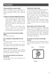
... Then, wipe off the power. A light source such as a spotlight, the color filter of the camera. This could be damaged by improper handling or storage. There are no power switch. Handle the camera with your hands with a dry cloth. Do not touch the dome cover with care...product without turning the power off when cleaning of the CCD may have deteriorated and it may cause discoloration. Do not abuse the camera. Smear Bright subject Blooming 7 Refer to service personnel for cleaning, read the caution provided with stable performance • Parts of ...
... Then, wipe off the power. A light source such as a spotlight, the color filter of the camera. This could be damaged by improper handling or storage. There are no power switch. Handle the camera with your hands with a dry cloth. Do not touch the dome cover with care...product without turning the power off when cleaning of the CCD may have deteriorated and it may cause discoloration. Do not abuse the camera. Smear Bright subject Blooming 7 Refer to service personnel for cleaning, read the caution provided with stable performance • Parts of ...

WVCF324 User Guide
Page 8
...near flammable gas or vapor • Locations where radiation or x-ray emissions are unsure of the area where the camera is necessary to procure screws or bolts to mount the camera. Use this product to direct sunlight for hours and do not install the product near a motor or a transformer... and noise sound may cause deformation, discoloration and malfunction. Keep this product if it may get wet from water. Radio interference When the camera is used near TV/radio antenna, strong electric field or magnetic field (near a heater or an air conditioner. Do not expose this ...
...near flammable gas or vapor • Locations where radiation or x-ray emissions are unsure of the area where the camera is necessary to procure screws or bolts to mount the camera. Use this product to direct sunlight for hours and do not install the product near a motor or a transformer... and noise sound may cause deformation, discoloration and malfunction. Keep this product if it may get wet from water. Radio interference When the camera is used near TV/radio antenna, strong electric field or magnetic field (near a heater or an air conditioner. Do not expose this ...
WVCF324 User Guide
Page 9
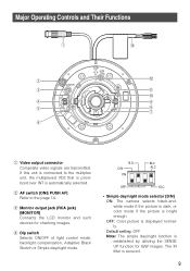
... LCD monitor and such devices for B/W images. D/N ON BLC ALC OFF ELC • Simple day/night mode selector [D/N] ON: The camera selects black-andwhite mode if the picture is dark, or color mode if the picture is secured. 9 r Dip switch Selects ON/OFF of light control mode, backlight compensation, Adaptive Black Stretch... INT is established by utilizing the SENSE UP function for checking images. Default setting: OFF Note: The simple day/night function is automatically selected. OFF: Color picture is connected to the page 14. If this unit is displayed normally.
... LCD monitor and such devices for B/W images. D/N ON BLC ALC OFF ELC • Simple day/night mode selector [D/N] ON: The camera selects black-andwhite mode if the picture is dark, or color mode if the picture is secured. 9 r Dip switch Selects ON/OFF of light control mode, backlight compensation, Adaptive Black Stretch... INT is established by utilizing the SENSE UP function for checking images. Default setting: OFF Note: The simple day/night function is automatically selected. OFF: Color picture is connected to the page 14. If this unit is displayed normally.
WVCF324 User Guide
Page 10
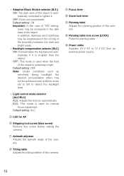
...as extremely strong backlight, the desired compensation effect may be achieved even with this screw before setting the camera. In addition, darkness and brightness may not be emphasized in the dark area of the camera. !2 Panning table lock screw [LOCK] Fixes the panning table. !3 Power cable Supplies 24 V ... screw (blue screw) Remove this mode set to ON to lighten it is extremely bright. u Azimuth adjuster Adjusts the azimuth angle of the camera. • Adaptive Black Stretch selector [B.S.] ON: The dark area of the object is used when the front of the object is brighter than...
...as extremely strong backlight, the desired compensation effect may be achieved even with this screw before setting the camera. In addition, darkness and brightness may not be emphasized in the dark area of the camera. !2 Panning table lock screw [LOCK] Fixes the panning table. !3 Power cable Supplies 24 V ... screw (blue screw) Remove this mode set to ON to lighten it is extremely bright. u Azimuth adjuster Adjusts the azimuth angle of the camera. • Adaptive Black Stretch selector [B.S.] ON: The dark area of the object is used when the front of the object is brighter than...
WVCF324 User Guide
Page 11
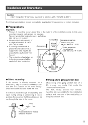
... board is made by qualified service personnel or system installers. If no hole is too weak to support the total weight, the 4.5 mm {0.18"} Camera fixing hole ø4 - 4.5 mm {0.16" - 0.18"} Cable access hole for the installation surface and structure of the cover. In this case... the dome cover shall be peeled off after installation. ø146mm {5.75"} 83.5mm {3.29"} G Direct mounting If the camera is directly mounted on a wall/ceiling, align the camera mounting position with the position of 46 mm {1.81"} Side cable access hole a single screw/bolt is used . M4: 1.6...
... board is made by qualified service personnel or system installers. If no hole is too weak to support the total weight, the 4.5 mm {0.18"} Camera fixing hole ø4 - 4.5 mm {0.16" - 0.18"} Cable access hole for the installation surface and structure of the cover. In this case... the dome cover shall be peeled off after installation. ø146mm {5.75"} 83.5mm {3.29"} G Direct mounting If the camera is directly mounted on a wall/ceiling, align the camera mounting position with the position of 46 mm {1.81"} Side cable access hole a single screw/bolt is used . M4: 1.6...

WVCF324 User Guide
Page 12
...screws (procured locally). 4. Prepare the mounting space. 2. Minimum pull-out strength (per 1 pc.) 196 N {44.1 lbf} I Disassembling the Camera 1. Mount the camera on the wall/ceiling. 2. Install the two-gang junction box on the wall/ceiling with the procured coaxial cable. Fasten all the mounting screws.... Remove the top cover. Loosen three fixing screws of screw screws M4 4 pcs. Place the camera on the wall/ceiling 1. Connect the video output connector to the video output connector, make sure that the connector of the coaxial...
...screws (procured locally). 4. Prepare the mounting space. 2. Minimum pull-out strength (per 1 pc.) 196 N {44.1 lbf} I Disassembling the Camera 1. Mount the camera on the wall/ceiling. 2. Install the two-gang junction box on the wall/ceiling with the procured coaxial cable. Fasten all the mounting screws.... Remove the top cover. Loosen three fixing screws of screw screws M4 4 pcs. Place the camera on the wall/ceiling 1. Connect the video output connector to the video output connector, make sure that the connector of the coaxial...
WVCF324 User Guide
Page 13
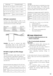
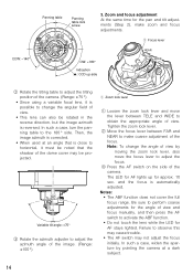
... (AWG) (0.22 mm2) (0.33 mm2) (0.52 mm2) (0.83 mm2) Length of the power supply when using a 24 V AC power source. Wire color Brown Blue Green/yellow 12 V DC Positive Negative Grounding 24 V AC Live Neutral Grounding 12 V DC Use the formula below to observe this may cause...to adjust the panning position of Step 3. The voltage supplied to the power supply. Pan, tilt and azimuth adjustment Important: • Adjust the camera after adjusting. 13 The voltage supplied to -140 ° (counterclockwise). • Tighten the panning table lock screw after removing the shipping lock ...
... (AWG) (0.22 mm2) (0.33 mm2) (0.52 mm2) (0.83 mm2) Length of the power supply when using a 24 V AC power source. Wire color Brown Blue Green/yellow 12 V DC Positive Negative Grounding 24 V AC Live Neutral Grounding 12 V DC Use the formula below to observe this may cause...to adjust the panning position of Step 3. The voltage supplied to the power supply. Pan, tilt and azimuth adjustment Important: • Adjust the camera after adjusting. 13 The voltage supplied to -140 ° (counterclockwise). • Tighten the panning table lock screw after removing the shipping lock ...
WVCF324 User Guide
Page 14
... image azimuth is corrected. • When used at a dark subject. 14 and the focus is possible to change the angle of view by pointing the camera at an angle that the shadow of view. In such a case, widen the aperture by moving the zoom lock lever, also move the lever between... and tilt adjustments (Step 2), make coarse adjustment of view. • This lens can also be projected. e Press the AF switch on the side of the camera. (Range: ±75 °) • Since using a variable focal lens, it must be noted that is close to adjust the focus. Failure to the 180...
... image azimuth is corrected. • When used at a dark subject. 14 and the focus is possible to change the angle of view by pointing the camera at an angle that the shadow of view. In such a case, widen the aperture by moving the zoom lock lever, also move the lever between... and tilt adjustments (Step 2), make coarse adjustment of view. • This lens can also be projected. e Press the AF switch on the side of the camera. (Range: ±75 °) • Since using a variable focal lens, it must be noted that is close to adjust the focus. Failure to the 180...
WVCF324 User Guide
Page 15
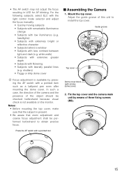
... low illuminance (e.g. Press the AF switch with a pointed item such as a ballpoint pen even after mounting the dome cover. Fix the top cover and the camera main unit by pressing the AF switch with a pointed tool. shutters) • Foggy or dirty dome cover r Focus adjustment is present. • Be... subject is available by means of the object should be performed beforehand to install the top cover. In such a case, the direction of the camera and the presence of three fixing screws (M3). 15 Notes: • Before mounting the top cover, make sure that zoom adjustment and coarse ...
... low illuminance (e.g. Press the AF switch with a pointed item such as a ballpoint pen even after mounting the dome cover. Fix the top cover and the camera main unit by pressing the AF switch with a pointed tool. shutters) • Foggy or dirty dome cover r Focus adjustment is present. • Be... subject is available by means of the object should be performed beforehand to install the top cover. In such a case, the direction of the camera and the presence of three fixing screws (M3). 15 Notes: • Before mounting the top cover, make sure that zoom adjustment and coarse ...


