Operating Instructions
Page 1
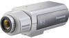
Operating Instructions Color CCTV Camera WV-CP500 Model No. Lens: Option Before attempting to connect or operate this product, please read these instructions carefully and save this manual. WV-CP504 This illustration represents WV-CP500. No model number suffix is shown in this manual for future use.
Operating Instructions Color CCTV Camera WV-CP500 Model No. Lens: Option Before attempting to connect or operate this product, please read these instructions carefully and save this manual. WV-CP504 This illustration represents WV-CP500. No model number suffix is shown in this manual for future use.
Operating Instructions
Page 2
...guide for further information about how to read PDF. Trademarks and registered trademarks Adobe and Reader are either registered trademarks or trademarks of the camera. This document explains how to configure the settings of Adobe Systems Incorporated in the United States and/or other countries. 2 When the ...Adobe® Reader® is required to install the camera. Adobe® Reader® is not installed on the PC, download the latest Adobe® Reader® from the Adobe web site and...
...guide for further information about how to read PDF. Trademarks and registered trademarks Adobe and Reader are either registered trademarks or trademarks of the camera. This document explains how to configure the settings of Adobe Systems Incorporated in the United States and/or other countries. 2 When the ...Adobe® Reader® is required to install the camera. Adobe® Reader® is not installed on the PC, download the latest Adobe® Reader® from the Adobe web site and...
Operating Instructions
Page 3
... Synchronization method selection [SYNC 22 Setting of scene change detection 20 Configure frame display 20 Configure alarm notification 21 Camera system setting [SYSTEM SETUP 22 10. Electronic sensitivity enhancement setting [SENS UP 12 6. Black-and-white mode ...Trademarks and registered trademarks 2 About the setup menus 4 Setup menu list 4 Basic operation 5 Screen transition diagram 6 Camera title setting [CAMERA ID 7 Camera operation setting [CAMERA SETUP 8 1. White balance setting [WHITE BAL 12 Manual fine adjustment of white balance 14 7. Light quantity control ...
... Synchronization method selection [SYNC 22 Setting of scene change detection 20 Configure frame display 20 Configure alarm notification 21 Camera system setting [SYSTEM SETUP 22 10. Electronic sensitivity enhancement setting [SENS UP 12 6. Black-and-white mode ...Trademarks and registered trademarks 2 About the setup menus 4 Setup menu list 4 Basic operation 5 Screen transition diagram 6 Camera title setting [CAMERA ID 7 Camera operation setting [CAMERA SETUP 8 1. White balance setting [WHITE BAL 12 Manual fine adjustment of white balance 14 7. Light quantity control ...
Operating Instructions
Page 4
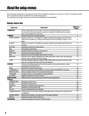
...8 9 11 12 12 12 14 14 15 22 22 23 24 25 26 27 29 29 29 29 30 31 31 31 32 4 CAMERA Performs the camera operation settings. WHITE BAL Specifies white balance adjustment. DNR Selects the level of the ALARM IN connector and the ALARM OUT connector. SYSTEM Performs...setup procedure when LANGUAGE is an example of this unit. It is possible to register and save the settings as a scene file in the camera shooting area. Perform the settings for each setting regarding intelligent VMD (Video Motion Detector) such as synchronization, alarm input/output, and privacy zone....
...8 9 11 12 12 12 14 14 15 22 22 23 24 25 26 27 29 29 29 29 30 31 31 31 32 4 CAMERA Performs the camera operation settings. WHITE BAL Specifies white balance adjustment. DNR Selects the level of the ALARM IN connector and the ALARM OUT connector. SYSTEM Performs...setup procedure when LANGUAGE is an example of this unit. It is possible to register and save the settings as a scene file in the camera shooting area. Perform the settings for each setting regarding intelligent VMD (Video Motion Detector) such as synchronization, alarm input/output, and privacy zone....
Operating Instructions
Page 5
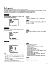
... • If the top screen of advanced setup screen: Press the setting button when "O" is a reversely highlighted part. MODEL WV-CP500 SERIES CAMERA ID OFF CAMERA SYSTEM BACK-FOCUS SPECIAL LANGUAGE END SETUP ENABLE Step 3 Move the cursor to the item to "ENABLE". The operations in the...the setting button. • Return to the top screen: Move the cursor to "TOP" and press the setting button. MODEL WV-CP500 SERIES CAMERA ID OFF CAMERA SYSTEM BACK-FOCUS SPECIAL LANGUAGE END SETUP DISABLE Step 1 Press the up or down button to move the cursor to be set ...
... • If the top screen of advanced setup screen: Press the setting button when "O" is a reversely highlighted part. MODEL WV-CP500 SERIES CAMERA ID OFF CAMERA SYSTEM BACK-FOCUS SPECIAL LANGUAGE END SETUP ENABLE Step 3 Move the cursor to the item to "ENABLE". The operations in the...the setting button. • Return to the top screen: Move the cursor to "TOP" and press the setting button. MODEL WV-CP500 SERIES CAMERA ID OFF CAMERA SYSTEM BACK-FOCUS SPECIAL LANGUAGE END SETUP DISABLE Step 1 Press the up or down button to move the cursor to be set ...
Operating Instructions
Page 6
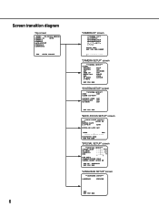
...LANGUAGE ENGLISH SET RET TOP END Screen transition diagram Top screen MODEL WV-CP500 SERIES CAMERA ID OFF CAMERA SYSTEM BACK-FOCUS SPECIAL LANGUAGE END SETUP ENABLE 6 "CAMERA ID" screen **CAMERA ID** 0123456789 ABCDEFGHIJKLM NOPQRSTUVWXYZ SPACE POSI RET TOP END RESET "CAMERA SETUP" screen **CAMERA SETUP** SCENE1 ALC/ELC ALC SHUTTER OFF AGC ON(HIGH) SENS ... XXXX RET TOP END "SPECIAL SETUP" screen **SPECIAL SETUP** CHROMA GAIN ...|...128 AP GAIN ...|... 32 PEDESTAL ...|... 32 HUE ...|... 0 - + PIX OFF COMMUNICATION COAX CAMERA RESET PUSH SW SER.NO.
...LANGUAGE ENGLISH SET RET TOP END Screen transition diagram Top screen MODEL WV-CP500 SERIES CAMERA ID OFF CAMERA SYSTEM BACK-FOCUS SPECIAL LANGUAGE END SETUP ENABLE 6 "CAMERA ID" screen **CAMERA ID** 0123456789 ABCDEFGHIJKLM NOPQRSTUVWXYZ SPACE POSI RET TOP END RESET "CAMERA SETUP" screen **CAMERA SETUP** SCENE1 ALC/ELC ALC SHUTTER OFF AGC ON(HIGH) SENS ... XXXX RET TOP END "SPECIAL SETUP" screen **SPECIAL SETUP** CHROMA GAIN ...|...128 AP GAIN ...|... 32 PEDESTAL ...|... 32 HUE ...|... 0 - + PIX OFF COMMUNICATION COAX CAMERA RESET PUSH SW SER.NO.
Operating Instructions
Page 7
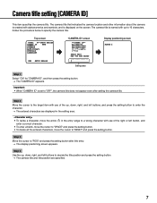
... the title position and press the setting button. → The camera title and title position are specified. 7 The camera title is displayed on the screen. Top screen MODEL WV-CP500 SERIES CAMERA ID ON CAMERA SYSTEM BACK-FOCUS SPECIAL LANGUAGE END SETUP ENABLE "CAMERA ID" screen **CAMERA ID** 0123456789 ABCDEFGHIJKLM NOPQRSTUVWXYZ SPACE POSI RET TOP END RESET Editing...
... the title position and press the setting button. → The camera title and title position are specified. 7 The camera title is displayed on the screen. Top screen MODEL WV-CP500 SERIES CAMERA ID ON CAMERA SYSTEM BACK-FOCUS SPECIAL LANGUAGE END SETUP ENABLE "CAMERA ID" screen **CAMERA ID** 0123456789 ABCDEFGHIJKLM NOPQRSTUVWXYZ SPACE POSI RET TOP END RESET Editing...
Operating Instructions
Page 8
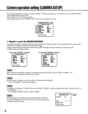
... displayed at night. Step 4 Edit the settings to be copied to "COPY(SCENE1)". → The settings of scene file. "CAMERA SETUP" screen q w e r t y u i o **CAMERA SETUP** SCENE1 ALC/ELC ALC SHUTTER OFF AGC ON(HIGH) SENS UP OFF WHITE BAL ATW1 DNR HIGH BW MODE AUTO1 i-VMD ...scene files can be saved as the default setting. For example, when different settings are to step 2. The settings configured on the "CAMERA SETUP" screen will be made on each setting screen inidicates a scene file number. **ALC CONT**(1) BACK LIGHT COMP SUPER-D5 ON ...
... displayed at night. Step 4 Edit the settings to be copied to "COPY(SCENE1)". → The settings of scene file. "CAMERA SETUP" screen q w e r t y u i o **CAMERA SETUP** SCENE1 ALC/ELC ALC SHUTTER OFF AGC ON(HIGH) SENS UP OFF WHITE BAL ATW1 DNR HIGH BW MODE AUTO1 i-VMD ...scene files can be saved as the default setting. For example, when different settings are to step 2. The settings configured on the "CAMERA SETUP" screen will be made on each setting screen inidicates a scene file number. **ALC CONT**(1) BACK LIGHT COMP SUPER-D5 ON ...
Operating Instructions
Page 9
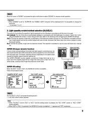
.... Subject in the bright area is available. Conversely, adjusting the lens brightness for the darker areas causes the brighter areas to notice. "CAMERA SETUP" screen **CAMERA SETUP** SCENE1 ALC/ELC ALC SHUTTER OFF AGC ON(HIGH) SENS UP OFF WHITE BAL ATW1 DNR HIGH BW MODE AUTO1 i-VMD RET.... "---" appears and "OFF" is high contrast between the bright and dark areas in a shooting zone, the dark area becomes less visible because the camera adjusts the iris in accordance with fixed iris or manual iris. Important: • When "SCENE2" is set for use of a lens with the ...
.... Subject in the bright area is available. Conversely, adjusting the lens brightness for the darker areas causes the brighter areas to notice. "CAMERA SETUP" screen **CAMERA SETUP** SCENE1 ALC/ELC ALC SHUTTER OFF AGC ON(HIGH) SENS UP OFF WHITE BAL ATW1 DNR HIGH BW MODE AUTO1 i-VMD RET.... "---" appears and "OFF" is high contrast between the bright and dark areas in a shooting zone, the dark area becomes less visible because the camera adjusts the iris in accordance with fixed iris or manual iris. Important: • When "SCENE2" is set for use of a lens with the ...
Operating Instructions
Page 12
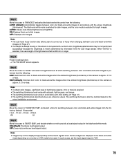
...is used , SW LED and the status of AUTO. perature of light stored on the CCD, and accordingly the image becomes brighter. WV-CU300, WV-CU354, WV-CU204, WV-CU254 • When the magnification of "SENS UP" is changeable in accordance with the illuminance of FIX, and the magnification is increased,... brighter when the illuminance of the color temperature ranges from the following . The setting of "SENS UP" are not correctly displayed. 4. The camera continuously measures the color tem- When the SUPER-D5 function is set to "OFF": OFF (default)/X2 AUTO/X4 AUTO/X6 AUTO/X10 AUTO...
...is used , SW LED and the status of AUTO. perature of light stored on the CCD, and accordingly the image becomes brighter. WV-CU300, WV-CU354, WV-CU204, WV-CU254 • When the magnification of "SENS UP" is changeable in accordance with the illuminance of FIX, and the magnification is increased,... brighter when the illuminance of the color temperature ranges from the following . The setting of "SENS UP" are not correctly displayed. 4. The camera continuously measures the color tem- When the SUPER-D5 function is set to "OFF": OFF (default)/X2 AUTO/X4 AUTO/X6 AUTO/X10 AUTO...
Operating Instructions
Page 13
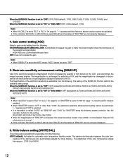
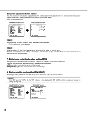
...light illuminating the subject is suitable for fine adjustment of the color temperature ranges from approx. 2 000 K to 10 000 K. The camera automatically achieves an optimal white balance under the bright blue sky or at nightfall. • The illumination of this adjust- The adjustment ... mostly highly-colored. • The photographic atmosphere is stable. When "AWC" is selected, the white balance needs to 6 000 K. "CAMERA SETUP" screen **CAMERA SETUP** SCENE1 ALC/ELC ALC SHUTTER OFF AGC ON(HIGH) SENS UP OFF WHITE BAL AWC PUSH SW DNR HIGH BW MODE AUTO1 i-VMD...
...light illuminating the subject is suitable for fine adjustment of the color temperature ranges from approx. 2 000 K to 10 000 K. The camera automatically achieves an optimal white balance under the bright blue sky or at nightfall. • The illumination of this adjust- The adjustment ... mostly highly-colored. • The photographic atmosphere is stable. When "AWC" is selected, the white balance needs to 6 000 K. "CAMERA SETUP" screen **CAMERA SETUP** SCENE1 ALC/ELC ALC SHUTTER OFF AGC ON(HIGH) SENS UP OFF WHITE BAL AWC PUSH SW DNR HIGH BW MODE AUTO1 i-VMD...
Operating Instructions
Page 14
...is selectable from the following: LOW: Low level of white balance The white balance is impossible to change the setting. (+ Page 23) "CAMERA SETUP" screen **CAMERA SETUP** SCENE1 ALC/ELC ALC SHUTTER OFF AGC ON(HIGH) SENS UP OFF WHITE BAL ATW1 DNR HIGH BW MODE AUTO1 i-VMD RET ...TOP END "BW MODE" screen **BW MODE**(1) AUTO1 LEVEL HIGH DURATION TIME .|.. "CAMERA SETUP" screen **CAMERA SETUP** SCENE1 ALC/ELC ALC SHUTTER OFF AGC ON(HIGH) SENS UP OFF WHITE BAL ATW1 DNR HIGH BW MODE AUTO1 i-VMD RET TOP...
...is selectable from the following: LOW: Low level of white balance The white balance is impossible to change the setting. (+ Page 23) "CAMERA SETUP" screen **CAMERA SETUP** SCENE1 ALC/ELC ALC SHUTTER OFF AGC ON(HIGH) SENS UP OFF WHITE BAL ATW1 DNR HIGH BW MODE AUTO1 i-VMD RET ...TOP END "BW MODE" screen **BW MODE**(1) AUTO1 LEVEL HIGH DURATION TIME .|.. "CAMERA SETUP" screen **CAMERA SETUP** SCENE1 ALC/ELC ALC SHUTTER OFF AGC ON(HIGH) SENS UP OFF WHITE BAL ATW1 DNR HIGH BW MODE AUTO1 i-VMD RET TOP...
Operating Instructions
Page 15
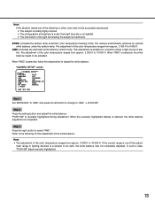
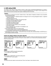
... brightness determination may not be used. Step 4 Move the cursor to black-and-white images when the ambient brightness (illuminance) of the camera is required. • The switching illuminance level varies with subjects, light sources, and lenses. • The switching illuminance level varies in...lx or less. The switching illuminance shall be decided based on a monitor or VCR model to be displayed appropriately without burst signals when camera images are reference values. ON: Displays black-and-white images. OFF: Does not provide any burst signal output. Note: • ...
... brightness determination may not be used. Step 4 Move the cursor to black-and-white images when the ambient brightness (illuminance) of the camera is required. • The switching illuminance level varies with subjects, light sources, and lenses. • The switching illuminance level varies in...lx or less. The switching illuminance shall be decided based on a monitor or VCR model to be displayed appropriately without burst signals when camera images are reference values. ON: Displays black-and-white images. OFF: Does not provide any burst signal output. Note: • ...
Operating Instructions
Page 16
...or too large • There are too many moving objects • Light reflected through a window or from a road surface • The camera is possible to detect only objects that keeps on moving for approx. 1 minute after turning on the power, after completing settings in the SETUP... menu, or after changing the camera direction are similar • False detection may cause detection failure. • Not enough difference in brightness between the background and the moving photographic...
...or too large • There are too many moving objects • Light reflected through a window or from a road surface • The camera is possible to detect only objects that keeps on moving for approx. 1 minute after turning on the power, after completing settings in the SETUP... menu, or after changing the camera direction are similar • False detection may cause detection failure. • Not enough difference in brightness between the background and the moving photographic...
Operating Instructions
Page 18
Up to "i-VMD" and press the setting button. → The "i-VMD SETUP" screen appears. Follow the procedure below. "CAMERA SETUP" screen **CAMERA SETUP** SCENE1 ALC/ELC ALC SHUTTER OFF AGC ON(HIGH) SENS UP OFF WHITE BAL ATW1 DNR HIGH BW MODE AUTO1 i-VMD RET TOP END "i-...
Up to "i-VMD" and press the setting button. → The "i-VMD SETUP" screen appears. Follow the procedure below. "CAMERA SETUP" screen **CAMERA SETUP** SCENE1 ALC/ELC ALC SHUTTER OFF AGC ON(HIGH) SENS UP OFF WHITE BAL ATW1 DNR HIGH BW MODE AUTO1 i-VMD RET TOP END "i-...
Operating Instructions
Page 20
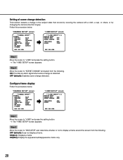
...display a frame. Follow the procedure below . OFF (default): Disables scene change is detected. Configure frame display Follow the procedure below . "CAMERA SETUP" screen **CAMERA SETUP** SCENE1 ALC/ELC ALC SHUTTER OFF AGC ON(HIGH) SENS UP OFF WHITE BAL ATW1 DNR HIGH BW MODE AUTO1 i-VMD RET ... Step 2 Move the cursor to "INDICATOR" and determine whether or not to "SCENE CHANGE" and select from the following . "CAMERA SETUP" screen **CAMERA SETUP** SCENE1 ALC/ELC ALC SHUTTER OFF AGC ON(HIGH) SENS UP OFF WHITE BAL ATW1 DNR HIGH BW MODE AUTO1 i-VMD ...
...display a frame. Follow the procedure below . OFF (default): Disables scene change is detected. Configure frame display Follow the procedure below . "CAMERA SETUP" screen **CAMERA SETUP** SCENE1 ALC/ELC ALC SHUTTER OFF AGC ON(HIGH) SENS UP OFF WHITE BAL ATW1 DNR HIGH BW MODE AUTO1 i-VMD RET ... Step 2 Move the cursor to "INDICATOR" and determine whether or not to "SCENE CHANGE" and select from the following . "CAMERA SETUP" screen **CAMERA SETUP** SCENE1 ALC/ELC ALC SHUTTER OFF AGC ON(HIGH) SENS UP OFF WHITE BAL ATW1 DNR HIGH BW MODE AUTO1 i-VMD ...

Operating Instructions
Page 21
... upon detection. 1TIME: Sends an alarm signal only once (100 ms) at detection start. 21 CONT (default): Continues to "ALARM" and configure alarm notification. "CAMERA SETUP" screen **CAMERA SETUP** SCENE1 ALC/ELC ALC SHUTTER OFF AGC ON(HIGH) SENS UP OFF WHITE BAL ATW1 DNR HIGH BW MODE AUTO1 i-VMD RET TOP...
... upon detection. 1TIME: Sends an alarm signal only once (100 ms) at detection start. 21 CONT (default): Continues to "ALARM" and configure alarm notification. "CAMERA SETUP" screen **CAMERA SETUP** SCENE1 ALC/ELC ALC SHUTTER OFF AGC ON(HIGH) SENS UP OFF WHITE BAL ATW1 DNR HIGH BW MODE AUTO1 i-VMD RET TOP...
Operating Instructions
Page 22
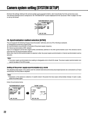
...10. When other than the VD2 synchronization is changeable only in the 60 Hz areas. Note: • Movement of the camera or presence of the camera and the criterial external synchronizing input signal (power) are connected to other than the VD2 synchronization method. Refer to page 5... for how to the camera system such as synchronization, alarm input/output terminal, and privacy zone. Note: • The power supply synchronization (LL) setting is ...
...10. When other than the VD2 synchronization is changeable only in the 60 Hz areas. Note: • Movement of the camera or presence of the camera and the criterial external synchronizing input signal (power) are connected to other than the VD2 synchronization method. Refer to page 5... for how to the camera system such as synchronization, alarm input/output terminal, and privacy zone. Note: • The power supply synchronization (LL) setting is ...
Operating Instructions
Page 23
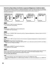
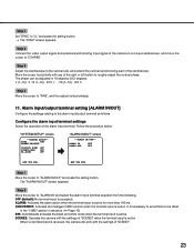
....5 16 (1--16) : 337.5 Step 4 Move the cursor to "ALARM IN" and select the alarm input terminal operation from the following. SCENE2: Operates the camera with the settings of "SCENE2" when the terminal input is accepted. Step 2 Move the cursor to "FINE", and fine adjust vertical phases. 11. OFF (... END Step 1 Move the cursor to the alarm input/output terminal as follows. Configure the alarm input terminal settings Select the operation of the camera to a 2-input oscilloscope, and move the cursor to roughly adjust the vertical phase. Step 3 Adjust the oscilloscope to "LL" and press ...
....5 16 (1--16) : 337.5 Step 4 Move the cursor to "ALARM IN" and select the alarm input terminal operation from the following. SCENE2: Operates the camera with the settings of "SCENE2" when the terminal input is accepted. Step 2 Move the cursor to "FINE", and fine adjust vertical phases. 11. OFF (... END Step 1 Move the cursor to the alarm input/output terminal as follows. Configure the alarm input terminal settings Select the operation of the camera to a 2-input oscilloscope, and move the cursor to roughly adjust the vertical phase. Step 3 Adjust the oscilloscope to "LL" and press ...

Operating Instructions
Page 24
..., i.e. Privacy zone setting [PRIVACY ZONE] When undesired portions in the black and white mode. 12. Note: • The privacy zone function is displayed in the camera shooting area (on the power. OFF (default): Displays the zone normally. right after turning on the screen) exist, those portions (privacy zone) are hidden. "SYSTEM...
..., i.e. Privacy zone setting [PRIVACY ZONE] When undesired portions in the black and white mode. 12. Note: • The privacy zone function is displayed in the camera shooting area (on the power. OFF (default): Displays the zone normally. right after turning on the screen) exist, those portions (privacy zone) are hidden. "SYSTEM...


