
Panaboard
Page 2
... or when the power has been cut off due to malfunction, repair or inadvertently, the memory contents may be held accountable for purchasing the Panasonic Electronic Board. Accessories Q'ty • Markers (Black, Red, Blue 1 each • Eraser 1 • Power cord 1 • Magnets 2 Q'ty • Software CD-ROM 1 • Operating Instructions 1 • Warranty...
... or when the power has been cut off due to malfunction, repair or inadvertently, the memory contents may be held accountable for purchasing the Panasonic Electronic Board. Accessories Q'ty • Markers (Black, Red, Blue 1 each • Eraser 1 • Power cord 1 • Magnets 2 Q'ty • Software CD-ROM 1 • Operating Instructions 1 • Warranty...

Panaboard
Page 10
..., blocking text or certain parts of a document/diagram. • Use only the included or designated markers and eraser. (See page 38.) Use of accessories other than 7 mm (9/32" ) in height when attaching documents to direct sunlight, near heating equipment, or near air-conditioning vents as this may disable... blemishes, if not, images will not be scanned properly. • When turn the power switch on after turning off, wait 2 seconds or more Panasonic electronic boards to make copies. • Make thick and dark lines inside the shaded area Approx. 20 mm (25/32") (on right) cannot ...
..., blocking text or certain parts of a document/diagram. • Use only the included or designated markers and eraser. (See page 38.) Use of accessories other than 7 mm (9/32" ) in height when attaching documents to direct sunlight, near heating equipment, or near air-conditioning vents as this may disable... blemishes, if not, images will not be scanned properly. • When turn the power switch on after turning off, wait 2 seconds or more Panasonic electronic boards to make copies. • Make thick and dark lines inside the shaded area Approx. 20 mm (25/32") (on right) cannot ...

Panaboard
Page 39
Installation Manual (for qualified service personnel) Table of Contents page For Your Safety 40 Assembling the unit 41 ●Accessories for assembling 41 ●Assembly 42 Electronic Board Operations Check 46 Repacking 47 Before installing this set, please read this manual completely. CLASS 1 LED PRODUCT 39 Installation
Installation Manual (for qualified service personnel) Table of Contents page For Your Safety 40 Assembling the unit 41 ●Accessories for assembling 41 ●Assembly 42 Electronic Board Operations Check 46 Repacking 47 Before installing this set, please read this manual completely. CLASS 1 LED PRODUCT 39 Installation

Panaboard
Page 41
No. Make sure that all of these parts are included in the package before proceeding. Part Name Power cord Illustration Q'ty 1 Remarks 1 Connector cover 4 Screw 4 4 Washer 1 5 Hexagonal wrench Installation 41 Assembling the unit ■ Accessories for assembling The package includes the parts for setting up the unit shown below.
No. Make sure that all of these parts are included in the package before proceeding. Part Name Power cord Illustration Q'ty 1 Remarks 1 Connector cover 4 Screw 4 4 Washer 1 5 Hexagonal wrench Installation 41 Assembling the unit ■ Accessories for assembling The package includes the parts for setting up the unit shown below.

Panaboard
Page 42
.... Then, remove the joints and the shipping box. • UB-2815C has twelve joints. • UB-2315C has ten joints. UB-2315C is a diagram of Accessory box] • Markers (Black, Red, Blue 1 each • Eraser 1 • Power cord 1 • Software CD-ROM . . . .1 • Operating Instructions. .1 • Warranty card*1 1 • Connector cover...
.... Then, remove the joints and the shipping box. • UB-2815C has twelve joints. • UB-2315C has ten joints. UB-2315C is a diagram of Accessory box] • Markers (Black, Red, Blue 1 each • Eraser 1 • Power cord 1 • Software CD-ROM . . . .1 • Operating Instructions. .1 • Warranty card*1 1 • Connector cover...

Panaboard
Page 43
... Note • Be careful not to 400 mm (1 9/16" ) and place it on the cushion (lower). 2) Remove the band holding the slider in. 2 Remove the accessory box, two stands and four cushions (upper). 4 Put the unit on the cushions (lower). 1) Lift the bottom (control box side) of the unit frame, and...
... Note • Be careful not to 400 mm (1 9/16" ) and place it on the cushion (lower). 2) Remove the band holding the slider in. 2 Remove the accessory box, two stands and four cushions (upper). 4 Put the unit on the cushions (lower). 1) Lift the bottom (control box side) of the unit frame, and...
Panaboard
Page 46
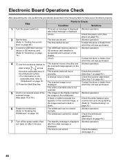
... 7 on page 45.) Check the scanner attachment. (See step 7 on page 45.) Contact the store or dealer from which the unit was purchased. 4 Use the accessory marker to "Scanning" on page 14.) The USB flash memory device or SD memory card installed is recognized and is displayed. (If not) Check the...
... 7 on page 45.) Check the scanner attachment. (See step 7 on page 45.) Contact the store or dealer from which the unit was purchased. 4 Use the accessory marker to "Scanning" on page 14.) The USB flash memory device or SD memory card installed is recognized and is displayed. (If not) Check the...

Panaboard
Page 47
Whiteboard Shipping box * This is equipped with one board stopper and one board stopper lever. models only. Installation 47 UB-2315C is a diagram of Accessory box] • Markers (Black, Red, Blue 1 each • Eraser 1 • Power cord 1 • Software CD-ROM . . . .1 • Operating Instructions. .1 • Warranty card*1 1 • Connector cover . . . . . .1 &#...-2815C. Repacking Perform Assembly Steps 2 through 8 on pages 43 - 45 in reverse to fasten the shipping box. Use the joints to repack the unit and accessories.
Whiteboard Shipping box * This is equipped with one board stopper and one board stopper lever. models only. Installation 47 UB-2315C is a diagram of Accessory box] • Markers (Black, Red, Blue 1 each • Eraser 1 • Power cord 1 • Software CD-ROM . . . .1 • Operating Instructions. .1 • Warranty card*1 1 • Connector cover . . . . . .1 &#...-2815C. Repacking Perform Assembly Steps 2 through 8 on pages 43 - 45 in reverse to fasten the shipping box. Use the joints to repack the unit and accessories.

Panaboard
Page 2
... address Dealer's address T_e_l Federal Communications Commission Requirements Note: This equipment has been tested and found to comply with the limits for purchasing the Panasonic Electronic Board. Accessories Q'ty • Markers (red, black, and blue 1 each • Operating Instructions 1 • Eraser 1 • Power cord 1 Q'ty • Letter size copy paper roll [10...
... address Dealer's address T_e_l Federal Communications Commission Requirements Note: This equipment has been tested and found to comply with the limits for purchasing the Panasonic Electronic Board. Accessories Q'ty • Markers (red, black, and blue 1 each • Operating Instructions 1 • Eraser 1 • Power cord 1 Q'ty • Letter size copy paper roll [10...

Panaboard
Page 7
... screen is not guaranteed to direct sunlight, near heating equipment, or near air-conditioning vents as vertical storage may cause stretching and/or discoloration of accessories other than those included or designated (such as oil-based markers) may damage the screen or result in hard-to-erase markings. • Store markers...
... screen is not guaranteed to direct sunlight, near heating equipment, or near air-conditioning vents as vertical storage may cause stretching and/or discoloration of accessories other than those included or designated (such as oil-based markers) may damage the screen or result in hard-to-erase markings. • Store markers...

Panaboard
Page 31
... assembling 32 ● Assembly 33 Electronic Board Operations Check 40 Repacking 41 Assembling the Optional Stand (UE-608005 42 ● Accessories 42 ● Assembly 43 Wall-mounting 46 ● Wall-mounting fixture 46 ● Wall-mounting procedure 47 ● Attaching the wall-mounting fixtures 48 Before ...
... assembling 32 ● Assembly 33 Electronic Board Operations Check 40 Repacking 41 Assembling the Optional Stand (UE-608005 42 ● Accessories 42 ● Assembly 43 Wall-mounting 46 ● Wall-mounting fixture 46 ● Wall-mounting procedure 47 ● Attaching the wall-mounting fixtures 48 Before ...

Panaboard
Page 32
Make sure that all of these parts are used for setting up the electronic board shown below. Assembling the Electronic Board ■ Accessories for assembling The package includes the parts for installing on the wall. 32 Part Name Board attachment (upper) [*Wall-mounting fixture (upper)] Board attachment (lower) [*...
Make sure that all of these parts are used for setting up the electronic board shown below. Assembling the Electronic Board ■ Accessories for assembling The package includes the parts for installing on the wall. 32 Part Name Board attachment (upper) [*Wall-mounting fixture (upper)] Board attachment (lower) [*...

Panaboard
Page 40
... to draw " " lights up and three copies (Normal operation) are not made. Contact the store or dealer from which the unit was purchased. 4 Use the accessory marker to the Operating Instructions (If not) page 10) Check the condition of the screen film surface. • Copying area (refer to Check Symptom Solutions...
... to draw " " lights up and three copies (Normal operation) are not made. Contact the store or dealer from which the unit was purchased. 4 Use the accessory marker to the Operating Instructions (If not) page 10) Check the condition of the screen film surface. • Copying area (refer to Check Symptom Solutions...

Panaboard
Page 41
Repacking Perform Assembly Steps 2 through 24 in reverse to the lower box. Board attachment (lower) Board attachment (upper) Cover (upper) Manuals, CD-ROM Paper holder A ï·ïB Copy paper roll Power cord Screws and spacers Eraser Cover (lower) Markers Screen unit Joint Printer unit Caution • When handling the screen unit, grasp the side cover on either side of screen. Do not grasp the screen film surface, as this may scratch it. Installation Manual 41 Use the joints to fasten the shipping box to repack the electronic board and accessories.
Repacking Perform Assembly Steps 2 through 24 in reverse to the lower box. Board attachment (lower) Board attachment (upper) Cover (upper) Manuals, CD-ROM Paper holder A ï·ïB Copy paper roll Power cord Screws and spacers Eraser Cover (lower) Markers Screen unit Joint Printer unit Caution • When handling the screen unit, grasp the side cover on either side of screen. Do not grasp the screen film surface, as this may scratch it. Installation Manual 41 Use the joints to fasten the shipping box to repack the electronic board and accessories.

Panaboard
Page 42
...pipe L 1 Cap 2 (not use . *1 A screw (short) is required when disassembling the electronic board; Assembling the Optional Stand (UE-608005) ■ Accessories The package box for the stopper screw of step 15 on page 37. ●Before assembly, be sure to lock the casters. please store it...- 1 tion extension 4 leg 1 Wrench (for stand) 1 2 Rear cover 1 Screw (long) 12 Rivet 6 Screw (short) 11*1 Washer 8 The accessory Wrench is used for the optional stand includes the parts noted below; No. Part name Illustration Q'ty No. Locking the casters (Push this side) 42...
...pipe L 1 Cap 2 (not use . *1 A screw (short) is required when disassembling the electronic board; Assembling the Optional Stand (UE-608005) ■ Accessories The package box for the stopper screw of step 15 on page 37. ●Before assembly, be sure to lock the casters. please store it...- 1 tion extension 4 leg 1 Wrench (for stand) 1 2 Rear cover 1 Screw (long) 12 Rivet 6 Screw (short) 11*1 Washer 8 The accessory Wrench is used for the optional stand includes the parts noted below; No. Part name Illustration Q'ty No. Locking the casters (Push this side) 42...

Electronic Board
Page 2
... disks, hard disks, optical disks, or other memory devices. 2 Please observe carefully the following items are based on the UB-5838C. Accessories Check that all of purchase Serial number Dealer's name and address Tel: Warning about saving data When the system storage device or any data... stored on separately available items, refer to malfunction, repair or inadvertently, the memory contents may be held accountable for purchasing the Panasonic Electronic Board. The manufacturer hereby declares that an item is saved. In the event that it cannot be lost or changed. For...
... disks, hard disks, optical disks, or other memory devices. 2 Please observe carefully the following items are based on the UB-5838C. Accessories Check that all of purchase Serial number Dealer's name and address Tel: Warning about saving data When the system storage device or any data... stored on separately available items, refer to malfunction, repair or inadvertently, the memory contents may be held accountable for purchasing the Panasonic Electronic Board. The manufacturer hereby declares that an item is saved. In the event that it cannot be lost or changed. For...

Electronic Board
Page 12
... inside the shaded area (on right) cannot be scanned. • Do not allow writing to remain on after turning off, wait 2 seconds or more Panasonic electronic boards to the unit. • Use only the included or designated markers and eraser. (See page 37.) Use of the screen. • Do... period of time as it may be exposed to direct sunlight, near heating equipment, or near air-conditioning vents as this may cause discoloration of accessories other devices. • When moving as this may cause the computer operation to become impossible. • Do not install the unit in hard-...
... inside the shaded area (on right) cannot be scanned. • Do not allow writing to remain on after turning off, wait 2 seconds or more Panasonic electronic boards to the unit. • Use only the included or designated markers and eraser. (See page 37.) Use of the screen. • Do... period of time as it may be exposed to direct sunlight, near heating equipment, or near air-conditioning vents as this may cause discoloration of accessories other devices. • When moving as this may cause the computer operation to become impossible. • Do not install the unit in hard-...

Electronic Board
Page 38
Especially, please read this manual carefully. CLASS 1 LED PRODUCT 38 Panasonic Communications Co., Ltd. cannot be held responsible for assembling 40 ● Assembly 41 Electronic Board Operations Check 45 ● Before Operation Check 45 &#..., perform installation with 2 people. Installation Manual (for qualified service personnel) Table of Contents page For Your Safety 39 Assembling the unit 40 ● Accessories for accidents or damage to property resulting from your dealer. • Before constructing or installing this set, please read "For Your Safety" carefully and ...
Especially, please read this manual carefully. CLASS 1 LED PRODUCT 38 Panasonic Communications Co., Ltd. cannot be held responsible for assembling 40 ● Assembly 41 Electronic Board Operations Check 45 ● Before Operation Check 45 &#..., perform installation with 2 people. Installation Manual (for qualified service personnel) Table of Contents page For Your Safety 39 Assembling the unit 40 ● Accessories for accidents or damage to property resulting from your dealer. • Before constructing or installing this set, please read "For Your Safety" carefully and ...

Electronic Board
Page 40
...Illustration Q'ty Remarks Washer 4 For assembling the stand Wall-mounting fixture 2 Clamp 1 Power cord 1 Note • Be sure to deliver the following accessories to the users. 1. Eraser 1 3. models only 1 For wall-mounting For power cord when using the stand The illustration of the power cord ...is for setting up the unit shown below. No. Assembling the unit ■ Accessories for assembling The package includes the parts for the United States. Operating Instructions 1 5. Make sure that all of the plug may ...
...Illustration Q'ty Remarks Washer 4 For assembling the stand Wall-mounting fixture 2 Clamp 1 Power cord 1 Note • Be sure to deliver the following accessories to the users. 1. Eraser 1 3. models only 1 For wall-mounting For power cord when using the stand The illustration of the power cord ...is for setting up the unit shown below. No. Assembling the unit ■ Accessories for assembling The package includes the parts for the United States. Operating Instructions 1 5. Make sure that all of the plug may ...
Electronic Board
Page 46
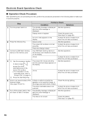
... entire scannable area is shown on the display. (Normal operation) (If not) Contact the store or dealer from which the unit was purchased. 4 Use the accessory marker The screen film moves smoothly (Normal operation) and the scanned image appears on to Check Condition Solutions 1 Turn the power switch on the display...
... entire scannable area is shown on the display. (Normal operation) (If not) Contact the store or dealer from which the unit was purchased. 4 Use the accessory marker The screen film moves smoothly (Normal operation) and the scanned image appears on to Check Condition Solutions 1 Turn the power switch on the display...