
Panaboard
Page 1
... problems with the operation of this unit, please read these instructions completely and keep them carefully for future reference. • This product is optional. [Wall-mounting] Electronic Board Operating Instructions With Installation Manual (for qualified service personnel) Model No.
... problems with the operation of this unit, please read these instructions completely and keep them carefully for future reference. • This product is optional. [Wall-mounting] Electronic Board Operating Instructions With Installation Manual (for qualified service personnel) Model No.

Panaboard
Page 6
after even if the electronic board is mounted on the surface Do not leave the disc out of the of the screen are hung in direct sunlight or near heat sources. To clean ...
after even if the electronic board is mounted on the surface Do not leave the disc out of the of the screen are hung in direct sunlight or near heat sources. To clean ...

Panaboard
Page 31
... 32 ● Assembly 33 Electronic Board Operations Check 40 Repacking 41 Assembling the Optional Stand (UE-608005 42 ● Accessories 42 ● Assembly 43 Wall-mounting 46 ● Wall-mounting fixture 46 ● Wall-mounting procedure 47 ● Attaching the wall-mounting fixtures 48 Before installing this set, please read this manual completely.
... 32 ● Assembly 33 Electronic Board Operations Check 40 Repacking 41 Assembling the Optional Stand (UE-608005 42 ● Accessories 42 ● Assembly 43 Wall-mounting 46 ● Wall-mounting fixture 46 ● Wall-mounting procedure 47 ● Attaching the wall-mounting fixtures 48 Before installing this set, please read this manual completely.

Panaboard
Page 32
... of these parts are used for setting up the electronic board shown below. Part Name Board attachment (upper) [*Wall-mounting fixture (upper)] Board attachment (lower) [*Wall-mounting fixture (lower)] Cover (upper) Illustration/Quantity Q'ty Remarks 1 1 1 1 Cover (lower) 6 6 (Long)...screen For screen 1 1 Paper holder B 1 Wrench 1 Power cord Wall-mounting template 1 Use the Wall-mounting template1 and 2 by pasting them together. * These names [Wall-mounting fixture (upper)/Wall-mounting fixture (lower)] are included in the package before proceeding. Assembling the Electronic ...
... of these parts are used for setting up the electronic board shown below. Part Name Board attachment (upper) [*Wall-mounting fixture (upper)] Board attachment (lower) [*Wall-mounting fixture (lower)] Cover (upper) Illustration/Quantity Q'ty Remarks 1 1 1 1 Cover (lower) 6 6 (Long)...screen For screen 1 1 Paper holder B 1 Wrench 1 Power cord Wall-mounting template 1 Use the Wall-mounting template1 and 2 by pasting them together. * These names [Wall-mounting fixture (upper)/Wall-mounting fixture (lower)] are included in the package before proceeding. Assembling the Electronic ...

Panaboard
Page 33
... film surface, as this may scratch it. • The shipping box, cushioning material, and other packing material will be necessary if you are using a wall-mounting fixture, refer to repackage the electronic board, so do not throw them away. 33 ■ Assembly 1 Assemble the optional stand or wall...
... film surface, as this may scratch it. • The shipping box, cushioning material, and other packing material will be necessary if you are using a wall-mounting fixture, refer to repackage the electronic board, so do not throw them away. 33 ■ Assembly 1 Assemble the optional stand or wall...

Panaboard
Page 34
...) Screen unit Cushions Caution • Touch the screen film surface gently to avoid any damage. 5 Attach the screen unit to the optional stand or wall mounting fixture. ■ If you are using the stand, refer to page 42. ■ If you are using the wall...
...) Screen unit Cushions Caution • Touch the screen film surface gently to avoid any damage. 5 Attach the screen unit to the optional stand or wall mounting fixture. ■ If you are using the stand, refer to page 42. ■ If you are using the wall...

Panaboard
Page 37
Use four screws for the optional stand and two screws for the printer unit. Board attachment (lower) Printer unit ■ Wall-mounting Caution • When attaching the printer unit, make sure the cable is not caught between the metallic frame and the printer unit. 37 Hang the ... (left side only). This prevents the user from adjusting the screen height at the lowest level by mistake. 17 Tighten the screws for the wall mounting. ■ Optional stand Installation Manual Stopper screw [ Screw (short) See page 42.] 16 Attach the printer unit.
Use four screws for the optional stand and two screws for the printer unit. Board attachment (lower) Printer unit ■ Wall-mounting Caution • When attaching the printer unit, make sure the cable is not caught between the metallic frame and the printer unit. 37 Hang the ... (left side only). This prevents the user from adjusting the screen height at the lowest level by mistake. 17 Tighten the screws for the wall mounting. ■ Optional stand Installation Manual Stopper screw [ Screw (short) See page 42.] 16 Attach the printer unit.

Panaboard
Page 46
...attach the electronic board to metal laths or wire laths can cause heat, smoke or a fire. Accidental electric leakage from the wall-mounting fixture bolts to mortared walls. Drill (and drill bit of wall construction. The position of the intended installation is critical for safe wall...-mounting, and depends on the nature of correct size) for the selected Panaboard. 1,440 mm (H) × 1,372 mm (W) [56.7" (H) × 54.0" (W)]. 3. ...
...attach the electronic board to metal laths or wire laths can cause heat, smoke or a fire. Accidental electric leakage from the wall-mounting fixture bolts to mortared walls. Drill (and drill bit of wall construction. The position of the intended installation is critical for safe wall...-mounting, and depends on the nature of correct size) for the selected Panaboard. 1,440 mm (H) × 1,372 mm (W) [56.7" (H) × 54.0" (W)]. 3. ...

Panaboard
Page 47
...to 23 on pages 33 to Wall-mounting template 2 (BOTTOM). 2) Tape the wall-mounting template on the wall. • When taping the template on the wall-mounting fixture are 1/4" in diameter. 2) After removing the wall-mounting template, attach the wall-mounting fixtures with the appropriate wall-mounting hardware. AB AB AB C C...to support the weight of supporting at least 784N [80 kgf (176 lbs.)]. 2 1) Assemble the wall-mounting template by taping the Wall-mounting template 1 (TOP) to 39 for the wall-mounting fixtures. • Holes on the wall, make sure it is level. 3 1) Drill holes in ...
...to 23 on pages 33 to Wall-mounting template 2 (BOTTOM). 2) Tape the wall-mounting template on the wall. • When taping the template on the wall-mounting fixture are 1/4" in diameter. 2) After removing the wall-mounting template, attach the wall-mounting fixtures with the appropriate wall-mounting hardware. AB AB AB C C...to support the weight of supporting at least 784N [80 kgf (176 lbs.)]. 2 1) Assemble the wall-mounting template by taping the Wall-mounting template 1 (TOP) to 39 for the wall-mounting fixtures. • Holes on the wall, make sure it is level. 3 1) Drill holes in ...

Panaboard
Page 48
...of the split-wing toggle grip firmly into the hole in the wall beneath so that the arms of the wall. ■ Attaching the wall-mounting fixtures The electronic board must be available in your area.) ●Attaching to the wall. Drill bit Metal or concrete wall Stud plug Drill ...tighten until the wallmounting fixture is securely fixed to metal or concrete walls Stud plugs (sold in stores) are presented here. (Other options may be mounted with the method most suited to the instructions for the particular stud plugs used . For the correct hole size, refer to the wall. 48 Insert...
...of the split-wing toggle grip firmly into the hole in the wall beneath so that the arms of the wall. ■ Attaching the wall-mounting fixtures The electronic board must be available in your area.) ●Attaching to the wall. Drill bit Metal or concrete wall Stud plug Drill ...tighten until the wallmounting fixture is securely fixed to metal or concrete walls Stud plugs (sold in stores) are presented here. (Other options may be mounted with the method most suited to the instructions for the particular stud plugs used . For the correct hole size, refer to the wall. 48 Insert...

Panaboard
Page 49
Wooden wall Installation Manual 49 Wall-mounting fixture Wood screw For the correct hole size, refer to wooden walls Use wood screws (sold in stores). ●Attaching to the instructions for the particular wood screws used.
Wooden wall Installation Manual 49 Wall-mounting fixture Wood screw For the correct hole size, refer to wooden walls Use wood screws (sold in stores). ●Attaching to the instructions for the particular wood screws used.

Electronic Board
Page 1
... refer to the Installation manual on page 38 through 55. • Before operating this equipment. For U.S.A. Installation performed by a qualified servicing dealer. [Stand (option)] [Wall-mounting] The unit in your area, please call 1-800-449-8989.
... refer to the Installation manual on page 38 through 55. • Before operating this equipment. For U.S.A. Installation performed by a qualified servicing dealer. [Stand (option)] [Wall-mounting] The unit in your area, please call 1-800-449-8989.
Electronic Board
Page 10
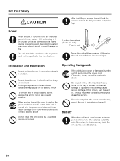
... or moving the unit, be used over an extended period of time, take the batteries out of time, switch it Off and unplug it is mounted on the wall. Locking the casters (Push this unit with the power cord attached, it may cause electric shock, current leakage or fire. Prolonged exposure...
... or moving the unit, be used over an extended period of time, take the batteries out of time, switch it Off and unplug it is mounted on the wall. Locking the casters (Push this unit with the power cord attached, it may cause electric shock, current leakage or fire. Prolonged exposure...

Electronic Board
Page 38
...Check 45 ● Setting the time 45 ● Operation Check Procedure 46 Repacking 47 Wall-Mounting Construction 48 ● Checking the Wall 48 ● Installing the Wall-Mounting Fixtures 49 ● Wall Types and Installation Procedures 51 Optional Stand Assembly (UE-608035 53 ...● Included Parts 53 ● Assembly Instructions 54 • Request assembly of the Electronic Board, stand and wall-mounting from incorrect installation. • When installing the Electronic Board, perform installation with 2 people. Especially, please read this set, please read...
...Check 45 ● Setting the time 45 ● Operation Check Procedure 46 Repacking 47 Wall-Mounting Construction 48 ● Checking the Wall 48 ● Installing the Wall-Mounting Fixtures 49 ● Wall Types and Installation Procedures 51 Optional Stand Assembly (UE-608035 53 ...● Included Parts 53 ● Assembly Instructions 54 • Request assembly of the Electronic Board, stand and wall-mounting from incorrect installation. • When installing the Electronic Board, perform installation with 2 people. Especially, please read this set, please read...

Electronic Board
Page 40
... accessories to the users. 1. USB cable 1 4. The shape of these parts are included in the package before proceeding. Operating Instructions 1 5. Eraser 1 3. models only 1 For wall-mounting For power cord when using the stand The illustration of the power cord is for setting up the unit shown below. Markers (Black, Red, Blue...
... accessories to the users. 1. USB cable 1 4. The shape of these parts are included in the package before proceeding. Operating Instructions 1 5. Eraser 1 3. models only 1 For wall-mounting For power cord when using the stand The illustration of the power cord is for setting up the unit shown below. Markers (Black, Red, Blue...

Electronic Board
Page 41
Assembling the unit ■ Assembly 1 Assemble the wall-mounting fixture or optional stand. • If you are using a wall-mounting fixture, refer to "Wall-Mounting Construction" on page 48. • If you are using a stand, refer to damage it does not strike the screen unit. (The screen unit... and lower sides of the center of the UB-5338C. Installation 41 Packing material Markers Washer, Clamp Screen unit USB cable Power cord Eraser Wall-mounting fixture Operating Instructions * This is a diagram of the unit. Do not grasp the screen film surface, as this may scratch it. • When...
Assembling the unit ■ Assembly 1 Assemble the wall-mounting fixture or optional stand. • If you are using a wall-mounting fixture, refer to "Wall-Mounting Construction" on page 48. • If you are using a stand, refer to damage it does not strike the screen unit. (The screen unit... and lower sides of the center of the UB-5338C. Installation 41 Packing material Markers Washer, Clamp Screen unit USB cable Power cord Eraser Wall-mounting fixture Operating Instructions * This is a diagram of the unit. Do not grasp the screen film surface, as this may scratch it. • When...

Electronic Board
Page 42
...the unit onto the shipping box with a screwdriver. (The fixed part of the rivets will be raised.) 6 Hang the two wall-mounting shafts of the unit to the wall-mounting fixtures. Note • Ensure that the cushioning material and other packing materials do not fit to step 10. Note • Make ...sure that the shafts fall into the groove of the wall-mounting fixture. 42 If the shafts do not strike the screen film. (Contact may damage the screen film.) • When using the stand, advance to ...
...the unit onto the shipping box with a screwdriver. (The fixed part of the rivets will be raised.) 6 Hang the two wall-mounting shafts of the unit to the wall-mounting fixtures. Note • Ensure that the cushioning material and other packing materials do not fit to step 10. Note • Make ...sure that the shafts fall into the groove of the wall-mounting fixture. 42 If the shafts do not strike the screen film. (Contact may damage the screen film.) • When using the stand, advance to ...

Electronic Board
Page 43
...wall. 9 Attach the lower frame cover removed in the stand) with 1 washers using the hexagonal wrench through holes A and C. [Normal height] 8 Fasten the wall-mounting clasps of the unit securely to "Electronic Board Operations Check" on page 45. This may deform the stand. • By tightening the two screws with... B, the unit will be positioned 100 mm (3 15/16") higher than normal height (1,930 mm [6' 4"]). [higher than normal height] C B A 43 Screw 1Washer C B A Installation Wall-mounting hardware Note • The 4 wall-mounting hardware are not included with the electronic board.
...wall. 9 Attach the lower frame cover removed in the stand) with 1 washers using the hexagonal wrench through holes A and C. [Normal height] 8 Fasten the wall-mounting clasps of the unit securely to "Electronic Board Operations Check" on page 45. This may deform the stand. • By tightening the two screws with... B, the unit will be positioned 100 mm (3 15/16") higher than normal height (1,930 mm [6' 4"]). [higher than normal height] C B A 43 Screw 1Washer C B A Installation Wall-mounting hardware Note • The 4 wall-mounting hardware are not included with the electronic board.

Electronic Board
Page 48
... is sufficient to install this unit only after thoroughly understanding the type of walls, the appropriate types of where the unit will be mounted and that it will not be behind the unit. 48 Note • Do not attach the electronic board to support the following ...weight. Make sure that the wall is strong enough to support the unit. 2. Wall-Mounting Construction ■ Checking the Wall When mounting on a wall, consult with the product) Drill, Screwdriver, Measuring tape, Level 8 screws (M6 size) 2. Accidental electric leakage ...
... is sufficient to install this unit only after thoroughly understanding the type of walls, the appropriate types of where the unit will be mounted and that it will not be behind the unit. 48 Note • Do not attach the electronic board to support the following ...weight. Make sure that the wall is strong enough to support the unit. 2. Wall-Mounting Construction ■ Checking the Wall When mounting on a wall, consult with the product) Drill, Screwdriver, Measuring tape, Level 8 screws (M6 size) 2. Accidental electric leakage ...

Electronic Board
Page 49
... in the hole position for UB-5838C and UB-5338C. • Make sure that are appropriate for the wall-mounting fixtures. • Drill holes that the position of the wall-mounting fixture is strong enough to support the unit. For UB-5838C: 1,373 N [140 kgf (309 lbf)] For... crooked). • The lateral tolerance of the hole position of the holes are level and perpendicular to insert the screws. Wall-Mounting Construction ■ Installing the Wall-Mounting Fixtures 1 Ensure that the wall is ± 1.5 mm (1/16"). 3 Drill 8 holes for the screws you are using. Installation ...
... in the hole position for UB-5838C and UB-5338C. • Make sure that are appropriate for the wall-mounting fixtures. • Drill holes that the position of the wall-mounting fixture is strong enough to support the unit. For UB-5838C: 1,373 N [140 kgf (309 lbf)] For... crooked). • The lateral tolerance of the hole position of the holes are level and perpendicular to insert the screws. Wall-Mounting Construction ■ Installing the Wall-Mounting Fixtures 1 Ensure that the wall is ± 1.5 mm (1/16"). 3 Drill 8 holes for the screws you are using. Installation ...
