
Service Guide
Page 1
... to 720 KB and 1.44 MB disks; The drive attached to the first connector is the only one present in some of micro floppy disk: • Double-Sided Double-Density (DSDD), formatted at 720 KB and used on 720 KB, 1.44 MB and 2.88 MB drives. • High-Density (HD), formatted at 1.44 MB and used on 1.44 MB and 2.88 MB drives. • Extra-Density...
... to 720 KB and 1.44 MB disks; The drive attached to the first connector is the only one present in some of micro floppy disk: • Double-Sided Double-Density (DSDD), formatted at 720 KB and used on 720 KB, 1.44 MB and 2.88 MB drives. • High-Density (HD), formatted at 1.44 MB and used on 1.44 MB and 2.88 MB drives. • Extra-Density...

Service Guide
Page 2
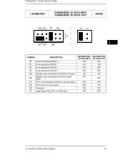
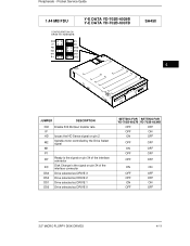
Pocket Service Guide PANASONIC JU-257-03T PANASONIC JU-257-03P SA450 JUMPER DESCRIPTION D0 Drive selected as DRIVE 0 D1 Drive selected as DRIVE 1 D2 Drive selected as DRIVE 2 D3 Drive selected as DRIVE 3 MO Spindle motor controlled by the Motor On signal MS Spindle motor controlled by the Drive Select signal DC Disk Change is the signal on pin 34 of the interface connector RY Ready is the signal on pin 34 of the interface connector TM Terminator SETTING OFF ON OFF OFF ON OFF ON OFF ON 4-2 3.5" MICRO FLOPPY DISK DRIVES 1.44 MB FDU Peripherals -
Pocket Service Guide PANASONIC JU-257-03T PANASONIC JU-257-03P SA450 JUMPER DESCRIPTION D0 Drive selected as DRIVE 0 D1 Drive selected as DRIVE 1 D2 Drive selected as DRIVE 2 D3 Drive selected as DRIVE 3 MO Spindle motor controlled by the Motor On signal MS Spindle motor controlled by the Drive Select signal DC Disk Change is the signal on pin 34 of the interface connector RY Ready is the signal on pin 34 of the interface connector TM Terminator SETTING OFF ON OFF OFF ON OFF ON OFF ON 4-2 3.5" MICRO FLOPPY DISK DRIVES 1.44 MB FDU Peripherals -
Service Guide
Page 3
... - Pocket Service Guide 1.44 MB FDU PANASONIC JU-257A-081P PANASONIC JU-257A-101P SA450 4 JUMPER DESCRIPTION D0 Drive selected as DRIVE 0 D1 Drive selected as DRIVE 1 D2 Drive selected as DRIVE 2 D3 Drive selected as DRIVE 3 MO Spindle motor controlled by the Motor On signal MS Spindle motor controlled by the Drive Select signal NC Pin 2...pin 2 output signal TM Terminator AT Mode Select PS2 (OFF) or PCAT (ON) SETTING FOR JU-257A-081P OFF ON OFF OFF ON OFF SETTING FOR JU-257A-101P OFF ON OFF OFF ON OFF OFF OFF OFF ON ON ON OFF OFF 3.5" MICRO FLOPPY DISK DRIVES 4-3
... - Pocket Service Guide 1.44 MB FDU PANASONIC JU-257A-081P PANASONIC JU-257A-101P SA450 4 JUMPER DESCRIPTION D0 Drive selected as DRIVE 0 D1 Drive selected as DRIVE 1 D2 Drive selected as DRIVE 2 D3 Drive selected as DRIVE 3 MO Spindle motor controlled by the Motor On signal MS Spindle motor controlled by the Drive Select signal NC Pin 2...pin 2 output signal TM Terminator AT Mode Select PS2 (OFF) or PCAT (ON) SETTING FOR JU-257A-081P OFF ON OFF OFF ON OFF SETTING FOR JU-257A-101P OFF ON OFF OFF ON OFF OFF OFF OFF ON ON ON OFF OFF 3.5" MICRO FLOPPY DISK DRIVES 4-3

Service Guide
Page 4
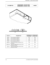
...44 MB FDU PANASONIC JU-257A-083P PANASONIC JU-257A-083PJ PANASONIC JU-257A-103P PANASONIC JU-257A-103PJ SA450 SWITCH DESCRIPTION SW3-0 Drive selected as DRIVE 0 SW3-1 Drive selected as DRIVE 1 SW3-2 Drive selected as DRIVE 2 SW3-3 Drive selected as DRIVE 3 SW2-MO Spindle motor controlled by the Motor On signal SW2-MS Spindle motor controlled by the Drive Select signal SW1-RY Disk... interface connector SETTING FOR JU-257A-083P/PJ OFF ON OFF OFF ON OFF ON OFF ON OFF ON OFF SETTING FOR JU-257A-103P/PJ OFF ON OFF OFF ON OFF ON OFF ON OFF OFF ON 4-4 3.5" MICRO FLOPPY DISK DRIVES
...44 MB FDU PANASONIC JU-257A-083P PANASONIC JU-257A-083PJ PANASONIC JU-257A-103P PANASONIC JU-257A-103PJ SA450 SWITCH DESCRIPTION SW3-0 Drive selected as DRIVE 0 SW3-1 Drive selected as DRIVE 1 SW3-2 Drive selected as DRIVE 2 SW3-3 Drive selected as DRIVE 3 SW2-MO Spindle motor controlled by the Motor On signal SW2-MS Spindle motor controlled by the Drive Select signal SW1-RY Disk... interface connector SETTING FOR JU-257A-083P/PJ OFF ON OFF OFF ON OFF ON OFF ON OFF ON OFF SETTING FOR JU-257A-103P/PJ OFF ON OFF OFF ON OFF ON OFF ON OFF OFF ON 4-4 3.5" MICRO FLOPPY DISK DRIVES

Service Guide
Page 5
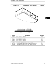
Peripherals - Pocket Service Guide 1.44 MB FDU PANASONIC JU-257A-293P SA450 4 SWITCH DESCRIPTION SW3-0 Drive selected as DRIVE 0 SW3-1 Drive selected as DRIVE 1 SW3-2 Drive selected as DRIVE 2 SW3-3 Drive selected as DRIVE 3 SW2-MO Spindle motor controlled by the Motor On signal SW2-MS Spindle motor controlled by the Drive Select signal SW1-RY Disk Change is the signal on pin 34 of the... output signal on pin 2 of the interface connector EX, EX, OUT SETTING OFF ON OFF OFF ON OFF ON OFF OFF ON OFF ON 3.5" MICRO FLOPPY DISK DRIVES 4-5
Peripherals - Pocket Service Guide 1.44 MB FDU PANASONIC JU-257A-293P SA450 4 SWITCH DESCRIPTION SW3-0 Drive selected as DRIVE 0 SW3-1 Drive selected as DRIVE 1 SW3-2 Drive selected as DRIVE 2 SW3-3 Drive selected as DRIVE 3 SW2-MO Spindle motor controlled by the Motor On signal SW2-MS Spindle motor controlled by the Drive Select signal SW1-RY Disk Change is the signal on pin 34 of the... output signal on pin 2 of the interface connector EX, EX, OUT SETTING OFF ON OFF OFF ON OFF ON OFF OFF ON OFF ON 3.5" MICRO FLOPPY DISK DRIVES 4-5
Service Guide
Page 6
Peripherals - Pocket Service Guide 1.44 MB FDU PANASONIC JU-257A-84P PANASONIC JU-257A-104P SA450 SWITCH DESCRIPTION SW3-0 SW3-1 SW3-2 SW3-3 SW2-NC SW2-OUT SW1-IN Drive selected as DRIVE 0 Drive selected as DRIVE 1 Drive selected as DRIVE 2 Drive selected as DRIVE 3 Pin 2 of the interface connector is not connected -HD is the output signal on pin 2 of the interface connector +HD is the input signal on pin 2 of the interface connector SETTING FOR JU-257A-84P OFF ON OFF OFF SETTING FOR JU-257A-104P OFF ON OFF OFF ON OFF OFF ON OFF OFF 4-6 3.5" MICRO FLOPPY DISK DRIVES
Peripherals - Pocket Service Guide 1.44 MB FDU PANASONIC JU-257A-84P PANASONIC JU-257A-104P SA450 SWITCH DESCRIPTION SW3-0 SW3-1 SW3-2 SW3-3 SW2-NC SW2-OUT SW1-IN Drive selected as DRIVE 0 Drive selected as DRIVE 1 Drive selected as DRIVE 2 Drive selected as DRIVE 3 Pin 2 of the interface connector is not connected -HD is the output signal on pin 2 of the interface connector +HD is the input signal on pin 2 of the interface connector SETTING FOR JU-257A-84P OFF ON OFF OFF SETTING FOR JU-257A-104P OFF ON OFF OFF ON OFF OFF ON OFF OFF 4-6 3.5" MICRO FLOPPY DISK DRIVES
Service Guide
Page 7
Pocket Service Guide 1.44 MB FDU PANASONIC JU-257A-294P SA450 4 SWITCH SW3-0 SW3-1 SW3-2 SW3-3 SW2-NC SW2-OUT SW1-IN DESCRIPTION Drive selected as DRIVE 0 Drive selected as DRIVE 1 Drive selected as DRIVE 2 Drive selected as DRIVE 3 Pin 2 of the interface connector is not connected -HD is the output signal on pin 2 of the interface connector +HD is the input signal on pin 2 of the interface connector SETTING OFF ON OFF OFF OFF OFF ON 3.5" MICRO FLOPPY DISK DRIVES 4-7 Peripherals -
Pocket Service Guide 1.44 MB FDU PANASONIC JU-257A-294P SA450 4 SWITCH SW3-0 SW3-1 SW3-2 SW3-3 SW2-NC SW2-OUT SW1-IN DESCRIPTION Drive selected as DRIVE 0 Drive selected as DRIVE 1 Drive selected as DRIVE 2 Drive selected as DRIVE 3 Pin 2 of the interface connector is not connected -HD is the output signal on pin 2 of the interface connector +HD is the input signal on pin 2 of the interface connector SETTING OFF ON OFF OFF OFF OFF ON 3.5" MICRO FLOPPY DISK DRIVES 4-7 Peripherals -

Service Guide
Page 8
Peripherals - Pocket Service Guide 1.44 MB FDU SONY MP-F17W-80D S3.O5'N' Y MB-F17W SA450 SWITCH 0 1 2 3 DESCRIPTION Drive selected as DRIVE 0 Drive selected as DRIVE 1 Drive selected as DRIVE 2 Drive selected as DRIVE 3 1.44 MB FDU SONY MP-F17W-82D SETTING OFF ON OFF OFF SA450 JUMPER DS0 DS1 DS2 DS3 HD DESCRIPTION Drive selected as DRIVE 0 Drive selected as DRIVE 1 Drive selected as DRIVE 2 Drive selected as DRIVE 3 HD sense is the signal on pin 2 of the interface connector SETTING OFF ON OFF OFF ON 4-8 3.5" MICRO FLOPPY DISK DRIVES
Peripherals - Pocket Service Guide 1.44 MB FDU SONY MP-F17W-80D S3.O5'N' Y MB-F17W SA450 SWITCH 0 1 2 3 DESCRIPTION Drive selected as DRIVE 0 Drive selected as DRIVE 1 Drive selected as DRIVE 2 Drive selected as DRIVE 3 1.44 MB FDU SONY MP-F17W-82D SETTING OFF ON OFF OFF SA450 JUMPER DS0 DS1 DS2 DS3 HD DESCRIPTION Drive selected as DRIVE 0 Drive selected as DRIVE 1 Drive selected as DRIVE 2 Drive selected as DRIVE 3 HD sense is the signal on pin 2 of the interface connector SETTING OFF ON OFF OFF ON 4-8 3.5" MICRO FLOPPY DISK DRIVES

Service Guide
Page 9
Pocket Service Guide 1.44 MB FDU SONY MP-F17W-84 SONY MP-F17W-85 SA450 4 SETTING ON MODEL MP-F17-84 SETTING ON MODEL MP-F17-85 JUMPER DESCRIPTION DS0 DS1 DENSITY STATUS Drive selected as DRIVE 0 Drive selected as DRIVE 1 Density Status is the signal on pin 2 of the interface connector SETTING FOR MP-F17-84 OFF ON SETTING FOR MP-F17-85 OFF ON OFF ON 3.5" MICRO FLOPPY DISK DRIVES 4-9 Peripherals -
Pocket Service Guide 1.44 MB FDU SONY MP-F17W-84 SONY MP-F17W-85 SA450 4 SETTING ON MODEL MP-F17-84 SETTING ON MODEL MP-F17-85 JUMPER DESCRIPTION DS0 DS1 DENSITY STATUS Drive selected as DRIVE 0 Drive selected as DRIVE 1 Density Status is the signal on pin 2 of the interface connector SETTING FOR MP-F17-84 OFF ON SETTING FOR MP-F17-85 OFF ON OFF ON 3.5" MICRO FLOPPY DISK DRIVES 4-9 Peripherals -
Service Guide
Page 11
...Service Guide 1.44 MB FDU CONFIGURATION ON DRIVE YD-702B-6037B Y-E DATA YD-702B-6039B Y-E DATA YD-702B-6037B SA450 4 JUMPER DESCRIPTION 300 Enable 300 Kbit/sec transfer rate IF HD Issues the HD Sense signal on pin 2 M2 Spindle motor controlled by the Drive Select signal M1...Drive selected as DRIVE 3 DS2 Drive selected as DRIVE 2 DS1 Drive selected as DRIVE 1 DS0 Drive selected as DRIVE 0 SETTING FOR SETTING FOR YD-702B-6037B YD-702B-6039B OFF OFF OFF ON ON OFF OFF OFF ON OFF OFF OFF OFF OFF ON ON OFF OFF OFF OFF ON ON OFF OFF 3.5" MICRO FLOPPY DISK DRIVES...
...Service Guide 1.44 MB FDU CONFIGURATION ON DRIVE YD-702B-6037B Y-E DATA YD-702B-6039B Y-E DATA YD-702B-6037B SA450 4 JUMPER DESCRIPTION 300 Enable 300 Kbit/sec transfer rate IF HD Issues the HD Sense signal on pin 2 M2 Spindle motor controlled by the Drive Select signal M1...Drive selected as DRIVE 3 DS2 Drive selected as DRIVE 2 DS1 Drive selected as DRIVE 1 DS0 Drive selected as DRIVE 0 SETTING FOR SETTING FOR YD-702B-6037B YD-702B-6039B OFF OFF OFF ON ON OFF OFF OFF ON OFF OFF OFF OFF OFF ON ON OFF OFF OFF OFF ON ON OFF OFF 3.5" MICRO FLOPPY DISK DRIVES...
Service Guide
Page 12
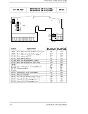
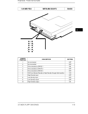
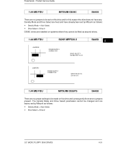
Pocket Service Guide 1.44 MB FDU MITSUBISHI MF-355C-58ML MITSUBISHI MF-355C-58MF SA450 JUMPER DESCRIPTION JP2-IS Front LED controlled by the Drive Select signal JP2-IU Front LED controlled by the Ready signal JP3-DS0 Drive selected as DRIVE 0 JP3-DS1 Drive selected as DRIVE 1 JP2-MM Motor start-up by the Motor-On...the Disk Change signal on pin 2 SETTING FOR SETTING FOR MF-355C-58ML MF-355C-58MF ON ON OFF OFF OFF OFF ON ON ON ON OFF OFF OFF OFF OFF OFF ON ON ON ON OFF OFF ON OFF OFF ON OFF OFF ON ON OFF OFF 4-12 3.5" MICRO FLOPPY DISK DRIVES ...
Pocket Service Guide 1.44 MB FDU MITSUBISHI MF-355C-58ML MITSUBISHI MF-355C-58MF SA450 JUMPER DESCRIPTION JP2-IS Front LED controlled by the Drive Select signal JP2-IU Front LED controlled by the Ready signal JP3-DS0 Drive selected as DRIVE 0 JP3-DS1 Drive selected as DRIVE 1 JP2-MM Motor start-up by the Motor-On...the Disk Change signal on pin 2 SETTING FOR SETTING FOR MF-355C-58ML MF-355C-58MF ON ON OFF OFF OFF OFF ON ON ON ON OFF OFF OFF OFF OFF OFF ON ON ON ON OFF OFF ON OFF OFF ON OFF OFF ON ON OFF OFF 4-12 3.5" MICRO FLOPPY DISK DRIVES ...
Service Guide
Page 13
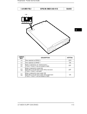
Pocket Service Guide 1.44 MB FDU SS01 EPSON SMD1040-418 SA450 4 JUMPER SS01 DESCRIPTION 1-6 Drive selected as DRIVE 0 1-2 Drive selected as DRIVE 1 3-8 Mode is selected by an internal sensor. 4-9 I/F pins 7, 9 and 11 are connected to GND. I /F pins 7, 9 and 11 are open. 4-9 7-8 Mode is set with ... level. Mode 2M is selected by signal HDI. Mode 2M is selected by input signal HDI. SETTING OFF ON OFF OFF ON 3.5" MICRO FLOPPY DISK DRIVES 4-13 I /F pins 7, 9 and 11 are connected to GND. 3-4 7-8 Mode is set with input signal HDI at high level. Peripherals -
Pocket Service Guide 1.44 MB FDU SS01 EPSON SMD1040-418 SA450 4 JUMPER SS01 DESCRIPTION 1-6 Drive selected as DRIVE 0 1-2 Drive selected as DRIVE 1 3-8 Mode is selected by an internal sensor. 4-9 I/F pins 7, 9 and 11 are connected to GND. I /F pins 7, 9 and 11 are open. 4-9 7-8 Mode is set with ... level. Mode 2M is selected by signal HDI. Mode 2M is selected by input signal HDI. SETTING OFF ON OFF OFF ON 3.5" MICRO FLOPPY DISK DRIVES 4-13 I /F pins 7, 9 and 11 are connected to GND. 3-4 7-8 Mode is set with input signal HDI at high level. Peripherals -
Service Guide
Page 14
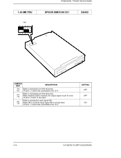
When medium 2HD is inserted, the output signal on pin 9 is at high level. Mode 2M is set when input signal HDI is low. SETTING OFF OFF ON 4-14 3.5" MICRO FLOPPY DISK DRIVES I/F pins 7, 9 and 11 are connected to the +5 V. I /F pins 1, 3 and 5 are open. 4-5 7-8 Mode is selected by input signal HDI. 1.44 MB FDU SS01 Peripherals - Pocket Service Guide EPSON SMD1040-321 SA450 JUMPER SS01 DESCRIPTION 3-8 Mode is selected by an internal sensor. 4-5 I /F pins 1, 3 and 5 are connected to the +5 V. 3-4 7-8 Mode is selected by an internal sensor.
When medium 2HD is inserted, the output signal on pin 9 is at high level. Mode 2M is set when input signal HDI is low. SETTING OFF OFF ON 4-14 3.5" MICRO FLOPPY DISK DRIVES I/F pins 7, 9 and 11 are connected to the +5 V. I /F pins 1, 3 and 5 are open. 4-5 7-8 Mode is selected by input signal HDI. 1.44 MB FDU SS01 Peripherals - Pocket Service Guide EPSON SMD1040-321 SA450 JUMPER SS01 DESCRIPTION 3-8 Mode is selected by an internal sensor. 4-5 I /F pins 1, 3 and 5 are connected to the +5 V. 3-4 7-8 Mode is selected by an internal sensor.

Service Guide
Page 15
... selected by an internal sensor. I /F pins 7, 9 and 11 are open. SETTING OFF ON ON OFF OFF 3.5" MICRO FLOPPY DISK DRIVES 4-15 Pocket Service Guide 1.44 MB FDU SS01 EPSON SMD1040-419 SA450 4 JUMPER SS01 1-6 1-2 3-8 4-9 3-4 7-8 4-9 7-8 DESCRIPTION Drive selected as DRIVE 0 Drive selected as DRIVE 1 The mode is selected by a low HDI input signal I /F pins 7, 9 and 11 are connected to GND...
... selected by an internal sensor. I /F pins 7, 9 and 11 are open. SETTING OFF ON ON OFF OFF 3.5" MICRO FLOPPY DISK DRIVES 4-15 Pocket Service Guide 1.44 MB FDU SS01 EPSON SMD1040-419 SA450 4 JUMPER SS01 1-6 1-2 3-8 4-9 3-4 7-8 4-9 7-8 DESCRIPTION Drive selected as DRIVE 0 Drive selected as DRIVE 1 The mode is selected by a low HDI input signal I /F pins 7, 9 and 11 are connected to GND...
Service Guide
Page 16
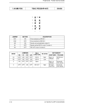
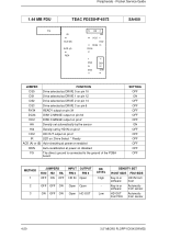
1.44 MB FDU Peripherals - Key-in or software HD IN from sensor 4-16 3.5" MICRO FLOPPY DISK DRIVES Pocket Service Guide TEAC FD235HF-4473 SA450 E HO HI D HA LHI C B DS0 DS1 A 2 1 JUMPER DS1 DS0 HA HI HO SETTING ON OFF ON OFF OFF DESCRIPTION Drive selected as DRIVE 1 Drive selected as DRIVE 0 Density set automatically (mode 2) Density set by HD IN...
1.44 MB FDU Peripherals - Key-in or software HD IN from sensor 4-16 3.5" MICRO FLOPPY DISK DRIVES Pocket Service Guide TEAC FD235HF-4473 SA450 E HO HI D HA LHI C B DS0 DS1 A 2 1 JUMPER DS1 DS0 HA HI HO SETTING ON OFF ON OFF OFF DESCRIPTION Drive selected as DRIVE 1 Drive selected as DRIVE 0 Density set automatically (mode 2) Density set by HD IN...

Service Guide
Page 17
Pocket Service Guide 1.44 MB FDU Y-E DATA YD-702D-6037D SA450 4 JUMPER IF, T1, T2 H2 H4 RY DC DS1 DS0 DESCRIPTION Automatic Switching operating mode Sends the HD sense signal on pin 2 Sends the HD sense signal on pin 4 The Ready signal is on pin 34 of the interface connector The Disk Change signal is on pin 34 of the interface connector Drive selected as DRIVE 1 Drive selected as DRIVE 0 SETTING OFF ON OFF OFF ON ON OFF 3.5" MICRO FLOPPY DISK DRIVES 4-17 Peripherals -
Pocket Service Guide 1.44 MB FDU Y-E DATA YD-702D-6037D SA450 4 JUMPER IF, T1, T2 H2 H4 RY DC DS1 DS0 DESCRIPTION Automatic Switching operating mode Sends the HD sense signal on pin 2 Sends the HD sense signal on pin 4 The Ready signal is on pin 34 of the interface connector The Disk Change signal is on pin 34 of the interface connector Drive selected as DRIVE 1 Drive selected as DRIVE 0 SETTING OFF ON OFF OFF ON ON OFF 3.5" MICRO FLOPPY DISK DRIVES 4-17 Peripherals -
Service Guide
Page 18
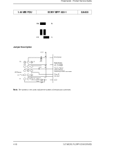
Pocket Service Guide SONY MPF 420-1 SA450 15 5 11 1 Jumper Description +5 V 15 12 10 5 GND GND HD Sensor 11 2 4 1 Amber Green Drive Select Mode Select +5V: HD IN Mode N.C.: LD IN Mode Density Select Ground: 1 MB Only HD Sensor: Auto Select Interface #2 pin: Interface Control Mode Drive ID HD OUT LED Note: The numbers in the circles indicate the number of interface pins connected. 4-18 3.5" MICRO FLOPPY DISK DRIVES 1.44 MB FDU Peripherals -
Pocket Service Guide SONY MPF 420-1 SA450 15 5 11 1 Jumper Description +5 V 15 12 10 5 GND GND HD Sensor 11 2 4 1 Amber Green Drive Select Mode Select +5V: HD IN Mode N.C.: LD IN Mode Density Select Ground: 1 MB Only HD Sensor: Auto Select Interface #2 pin: Interface Control Mode Drive ID HD OUT LED Note: The numbers in the circles indicate the number of interface pins connected. 4-18 3.5" MICRO FLOPPY DISK DRIVES 1.44 MB FDU Peripherals -
Service Guide
Page 19
Peripherals - Pocket Service Guide 1.44 MB FDU MITSUMI D359T3 SA450 4 10 9 8 6 7 5 3 4 2 1 JUMPER POSITION 1 2 3 4 5 6 7 8 9 10 DESCRIPTION Not connected Not connected Drive selected as DRIVE 1 Drive selected as DRIVE 2 Drive selected as DRIVE 0 Shift from Normal Density to High Density through disk insertion High Density input Low Density input Low Density output High Density output SETTING OFF OFF ON OFF OFF ON OFF OFF OFF ON 3.5" MICRO FLOPPY DISK DRIVES 4-19
Peripherals - Pocket Service Guide 1.44 MB FDU MITSUMI D359T3 SA450 4 10 9 8 6 7 5 3 4 2 1 JUMPER POSITION 1 2 3 4 5 6 7 8 9 10 DESCRIPTION Not connected Not connected Drive selected as DRIVE 1 Drive selected as DRIVE 2 Drive selected as DRIVE 0 Shift from Normal Density to High Density through disk insertion High Density input Low Density input Low Density output High Density output SETTING OFF OFF ON OFF OFF ON OFF OFF OFF ON 3.5" MICRO FLOPPY DISK DRIVES 4-19
Service Guide
Page 20
... Key-in or software HD IN from host Key-in or software Automatic from sensor HD OUT Automatic from FDU from sensor 4-20 3.5" MICRO FLOPPY DISK DRIVES Pocket Service Guide 1.44 MB FDU FG TEAC FD235HF-6573 IR 0V ACD (B) ACD (A) 0V REN HS HA HI HI2 HO HO2 2 DC2 34 DC34 DC RY34 RY... 6 DS3 DS DS2 14 12 DS1 DS DS0 10 SA450 JUMPER FUNCTION DS0 Drive selected as DRIVE 0 on pin 10 DS1 Drive selected as DRIVE 1 on pin 12 DS2 Drive selected as DRIVE...
... Key-in or software HD IN from host Key-in or software Automatic from sensor HD OUT Automatic from FDU from sensor 4-20 3.5" MICRO FLOPPY DISK DRIVES Pocket Service Guide 1.44 MB FDU FG TEAC FD235HF-6573 IR 0V ACD (B) ACD (A) 0V REN HS HA HI HI2 HO HO2 2 DC2 34 DC34 DC RY34 RY... 6 DS3 DS DS2 14 12 DS1 DS DS0 10 SA450 JUMPER FUNCTION DS0 Drive selected as DRIVE 0 on pin 10 DS1 Drive selected as DRIVE 1 on pin 12 DS2 Drive selected as DRIVE...
Service Guide
Page 21
...; Density Mode = Auto Select • Drive Select = Drive 2. 3.5" MICRO FLOPPY DISK DRIVES 4-21 The Density Mode and Drive Select parameters cannot be changed and are factory-set by Mitsumi as second drives. 1.44 MB FDU SONY MPF520-3 JUMPERS POWER SUPPLY CONNECTOR DRIVE SELECT 1 (configuration to use) SA450 4 JUMPERS POWER SUPPLY CONNECTOR DRIVE SELECT 0 (Do not use) 1.44 MB FDU MITSUMI D359T5 SA450 There...
...; Density Mode = Auto Select • Drive Select = Drive 2. 3.5" MICRO FLOPPY DISK DRIVES 4-21 The Density Mode and Drive Select parameters cannot be changed and are factory-set by Mitsumi as second drives. 1.44 MB FDU SONY MPF520-3 JUMPERS POWER SUPPLY CONNECTOR DRIVE SELECT 1 (configuration to use) SA450 4 JUMPERS POWER SUPPLY CONNECTOR DRIVE SELECT 0 (Do not use) 1.44 MB FDU MITSUMI D359T5 SA450 There...


