
Service Manual
Page 7
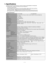
...*4 CF-19FHGAXBM CF-19FDGAXVM Intel® Core™ 2 Duo Processor U7500 (1.06 GHz, 2 MB*1 L2 cache, 533 MHz FSB) Intel® GM965 1 GB (4 GB Max.) UMA (384 MB Max.) 80 GB Display Method Internal LCD*5 External Display*6 Wireless LAN*7 BluetoothTM *8 LAN Modem Sound Security Chip 10.4 XGA type (TFT) 65,536/16...
...*4 CF-19FHGAXBM CF-19FDGAXVM Intel® Core™ 2 Duo Processor U7500 (1.06 GHz, 2 MB*1 L2 cache, 533 MHz FSB) Intel® GM965 1 GB (4 GB Max.) UMA (384 MB Max.) 80 GB Display Method Internal LCD*5 External Display*6 Wireless LAN*7 BluetoothTM *8 LAN Modem Sound Security Chip 10.4 XGA type (TFT) 65,536/16...
Service Manual
Page 8
...= 1,000,000,000 bytes. The size of the Video Memory cannot be set by TOSHIBA*8 , Wireless Switch Utility, Hotkey Settings, Battery Recalibration Utility, Panasonic Hand Writing*20, Software Keyboard*20, Display Rotation Tool, InÞneon TPM Professional Package*21, Recover ProTM 6*21 or Recover ProTM VX*21 , ...RF Frequency Band 2.0 + EDR FHSS system Channels 1 to 240 V AC adaptor. Operation on the usage conditions. *17 Measured using MobileMark™ 2005 (LCD brightness: 60 cd/m2) *18 Approx. 0.9 W when the battery pack is fully charged (or not being charged) and the computer is OFF. *19...
...= 1,000,000,000 bytes. The size of the Video Memory cannot be set by TOSHIBA*8 , Wireless Switch Utility, Hotkey Settings, Battery Recalibration Utility, Panasonic Hand Writing*20, Software Keyboard*20, Display Rotation Tool, InÞneon TPM Professional Package*21, Recover ProTM 6*21 or Recover ProTM VX*21 , ...RF Frequency Band 2.0 + EDR FHSS system Channels 1 to 240 V AC adaptor. Operation on the usage conditions. *17 Measured using MobileMark™ 2005 (LCD brightness: 60 cd/m2) *18 Approx. 0.9 W when the battery pack is fully charged (or not being charged) and the computer is OFF. *19...
Service Manual
Page 9
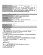
... the instruction manual of the wireless device. : Caps lock : Numeric key (NumLk) : Scroll lock (ScrLk) : Hard disk drive status F: Tablet Buttons Reference Manual "Tablet Buttons" G: LCD Reference Manual "Touchscreen" Reference Manual "Digitizer" H: Display Release Latch I: Speaker Reference Manual "Key Combinations" J: Function Key Reference Manual "Key Combinations" K: Keyboard L: Hard Disk Drive Reference...
... the instruction manual of the wireless device. : Caps lock : Numeric key (NumLk) : Scroll lock (ScrLk) : Hard disk drive status F: Tablet Buttons Reference Manual "Tablet Buttons" G: LCD Reference Manual "Touchscreen" Reference Manual "Digitizer" H: Display Release Latch I: Speaker Reference Manual "Key Combinations" J: Function Key Reference Manual "Key Combinations" K: Keyboard L: Hard Disk Drive Reference...
Service Manual
Page 13
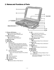
...NG OK Power lamp NO check YES Inverter board NG OK Replace AC Adaptor/Battery Check contact condition of POST NG OK Replace LCD back light. Replace main board. OK Return set should all keys cannot be removed before operation check. 2. Replace main board.... operation. Check inverter cable continuity. Replace main board (Check fuse at power source). Starts but operates unstably. Replace if defective. Replace LCD unit. Know-how of diagnosis upon occurrence of trouble in starting NG Replace main board. SETNADRT Set cannot be turned ON , Set ...
...NG OK Power lamp NO check YES Inverter board NG OK Replace AC Adaptor/Battery Check contact condition of POST NG OK Replace LCD back light. Replace main board. OK Return set should all keys cannot be removed before operation check. 2. Replace main board.... operation. Check inverter cable continuity. Replace main board (Check fuse at power source). Starts but operates unstably. Replace if defective. Replace LCD unit. Know-how of diagnosis upon occurrence of trouble in starting NG Replace main board. SETNADRT Set cannot be turned ON , Set ...
Service Manual
Page 22
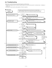
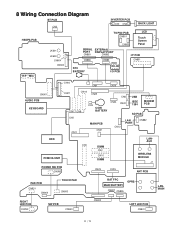
8 Wiring Connection Diagram BT PCB CN2 INVERTER PCB CN1 CN2 BACK LIGHT HSDPA PCB TS PS2 PCB CN901 CN900 LCD Touch Screen Panel JK601 JK600 CN604 CN600 SERIAL EXTERNAL PORT DISPLAY PORT CN881 CN882 CN880 RTC BATTERY CN883 JK880 DC-IN I/O PCB I/F PCB CN851 H/P MIC ...
8 Wiring Connection Diagram BT PCB CN2 INVERTER PCB CN1 CN2 BACK LIGHT HSDPA PCB TS PS2 PCB CN901 CN900 LCD Touch Screen Panel JK601 JK600 CN604 CN600 SERIAL EXTERNAL PORT DISPLAY PORT CN881 CN882 CN880 RTC BATTERY CN883 JK880 DC-IN I/O PCB I/F PCB CN851 H/P MIC ...
Service Manual
Page 26
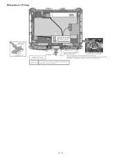
Disconnect the 2 LCD Cables. (CN8,CN17) DU PCB Antenna PCB Plate gray cable black cable white cable 2. Remove the BAT FPC Ass'y. 9. Remove the 2 Screws and the 3 Screws . 4. ...
Disconnect the 2 LCD Cables. (CN8,CN17) DU PCB Antenna PCB Plate gray cable black cable white cable 2. Remove the BAT FPC Ass'y. 9. Remove the 2 Screws and the 3 Screws . 4. ...

Service Manual
Page 28
... : DXYN4+J7FNL Remove the Pad PCB. 1. Screws : DFHE5025XA 3. Display unit is half-rotated and removes the 2 Screws . 4. 9.1.13. Remove the LCD Hinge Cover. Remove the 4 Screws . 5. Removing the Display unit LCD Hinge Cover 1. Turn the computer over. 6. Remove the Display Unit. Disconnect the 2 Cables from the 2 Connectors (CN805,CN807). 2. Remove the Operation...
... : DXYN4+J7FNL Remove the Pad PCB. 1. Screws : DFHE5025XA 3. Display unit is half-rotated and removes the 2 Screws . 4. 9.1.13. Remove the LCD Hinge Cover. Remove the 4 Screws . 5. Removing the Display unit LCD Hinge Cover 1. Turn the computer over. 6. Remove the Display Unit. Disconnect the 2 Cables from the 2 Connectors (CN805,CN807). 2. Remove the Operation...

Service Manual
Page 29
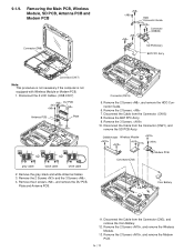
... and Tablet Latch Cover. 4. Remove the Cable Holder. 2. Screws : DXYN3+J8FNL 9.1.17. Remove the TS PS2 PCB, then remove the LCD unit. 9.1.18. Remove the 2 Screws . 6. Remove the LAN AUX Antenna PCB. 7. Remove the 2 Screws . 8. Remove the Pen... . 6. Remove the 2 Screws . 3. Removing the LCD Hinge Cable Holder Plate Cable Holder Plate Cable Holder LCD Plate Hinge Cable Holder LCD Cable Holder Sheet Cable Holder 1. Removing the LCD Rear Case LCD Rear Case Antenna Cover Tablet Latch Cover Antenna Cover 1. ...
... and Tablet Latch Cover. 4. Remove the Cable Holder. 2. Screws : DXYN3+J8FNL 9.1.17. Remove the TS PS2 PCB, then remove the LCD unit. 9.1.18. Remove the 2 Screws . 6. Remove the LAN AUX Antenna PCB. 7. Remove the 2 Screws . 8. Remove the Pen... . 6. Remove the 2 Screws . 3. Removing the LCD Hinge Cable Holder Plate Cable Holder Plate Cable Holder LCD Plate Hinge Cable Holder LCD Cable Holder Sheet Cable Holder 1. Removing the LCD Rear Case LCD Rear Case Antenna Cover Tablet Latch Cover Antenna Cover 1. ...
Service Manual
Page 31
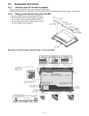
... Cloth and Heat Spreader cannot be recycled. Use new parts. 9.2.2. Lengthwise : Match to 0.5 mm at the far side.) LCD PWB Spacer Ass'y Insert this between LCD PCB & LCD Frame. Attention when CF-19 series is repaired ï Please execute writing BIOS ID when you exchange the Main Board. ï...; Parts (Sheet and rubber) etc. Holder Sheet 0 0.5mm LCD Side Cushion A Attach to the side surface if the Frame. (Match to the end of the frame. (0 to the Connectors (CN900 and CN901). 3. ...
... Cloth and Heat Spreader cannot be recycled. Use new parts. 9.2.2. Lengthwise : Match to 0.5 mm at the far side.) LCD PWB Spacer Ass'y Insert this between LCD PCB & LCD Frame. Attention when CF-19 series is repaired ï Please execute writing BIOS ID when you exchange the Main Board. ï...; Parts (Sheet and rubber) etc. Holder Sheet 0 0.5mm LCD Side Cushion A Attach to the side surface if the Frame. (Match to the end of the frame. (0 to the Connectors (CN900 and CN901). 3. ...

Service Manual
Page 32
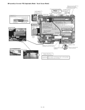
...MIl Cover. Digitizer PCB Ass'y Ensure the connector is connected securely. 10 2mm ■ Assembly of the Inverter board when attaching. ■ Assembly of LCD Back Damper (Application Model : Digitizer Model) PCB 33 35mm Attch to the middle line. Crosswise : Match to the side surface of the Frame. ...Lengthwise : Match to 0.5 mm at the far side. Screw the Board together 0 0.5mm LCD Back Dumper Remove the Release Paper on the side. Inverter MIL Cover Insert from the direction of the Frame within 0 to the...
...MIl Cover. Digitizer PCB Ass'y Ensure the connector is connected securely. 10 2mm ■ Assembly of the Inverter board when attaching. ■ Assembly of LCD Back Damper (Application Model : Digitizer Model) PCB 33 35mm Attch to the middle line. Crosswise : Match to the side surface of the Frame. ...Lengthwise : Match to 0.5 mm at the far side. Screw the Board together 0 0.5mm LCD Back Dumper Remove the Release Paper on the side. Inverter MIL Cover Insert from the direction of the Frame within 0 to the...
Service Manual
Page 33
... TS middle of right and left sides on the Back Dumper as shown below and overlap on the CCFL Cable. Details of cable LCD Ass'y Details of "A" Ensure the edge of the conductive fabric is front. Attach the surplus of the right and left . Sield Sheet Avoid getting under ...the Sheet. LCD Side Cushion E 12 Connector Insert it between the ribs. (Fit to the Cabinet.) 0 3mm Inverter Ass'y The gap side is not frayed. 1 2 mm A S5 Inverter...
... TS middle of right and left sides on the Back Dumper as shown below and overlap on the CCFL Cable. Details of cable LCD Ass'y Details of "A" Ensure the edge of the conductive fabric is front. Attach the surplus of the right and left . Sield Sheet Avoid getting under ...the Sheet. LCD Side Cushion E 12 Connector Insert it between the ribs. (Fit to the Cabinet.) 0 3mm Inverter Ass'y The gap side is not frayed. 1 2 mm A S5 Inverter...

Service Manual
Page 34
■ Assembly of Inverter PCB (Application Model : Digitizer Model) Details of cable 0 0 Inverter Ass'y LCD Back Dumper S5 Conductive Tape Attach coming over the end of steel plate by 1 to 2 mm. 0 1mm Avoid running over the rib Safety Working S2 CAUTION S1:Insulation S2:Pinching Cables S3:Sharp Edge S4:Part No. Check S5:Others
■ Assembly of Inverter PCB (Application Model : Digitizer Model) Details of cable 0 0 Inverter Ass'y LCD Back Dumper S5 Conductive Tape Attach coming over the end of steel plate by 1 to 2 mm. 0 1mm Avoid running over the rib Safety Working S2 CAUTION S1:Insulation S2:Pinching Cables S3:Sharp Edge S4:Part No. Check S5:Others

Service Manual
Page 35
Match to the marking line. 0.5 mm LCD Side Cushion B Touch Screen Ass'y 0 1mm TS Spacer A 0 1mm Match to the marking line. 0.5 mm NG Laminate T/S Laminate Protect Sheet Attach it to the front ... TS Spacer B TS Spacer B Ensure 4 and 5 do not run over the display side. ■ Assembly of the Cabinet. 0 to 0.5 mm Attach the surface to the LCD Front.
Match to the marking line. 0.5 mm LCD Side Cushion B Touch Screen Ass'y 0 1mm TS Spacer A 0 1mm Match to the marking line. 0.5 mm NG Laminate T/S Laminate Protect Sheet Attach it to the front ... TS Spacer B TS Spacer B Ensure 4 and 5 do not run over the display side. ■ Assembly of the Cabinet. 0 to 0.5 mm Attach the surface to the LCD Front.

Service Manual
Page 37
...the edge of "A" Avoid running over the rib, etc.. Screw EVDO/EDGE Antenna S2 Details of Cabinet Screw EVDO-AUX Screw Match to the LCD Hinge. 2. Screw Put the Cable on each hook Cable Cushion Tape Pen Holder Cable Cushion Put the center of Antenna Cable Safety Working CAUTION... antenna cables. Check S5:Others S3:Sharp Edge S2 Details of Cabinet Avoid running over the rib, etc.. Wind the Cable coming out of the LCD Unit counterclockwise to the edge of "B" Avoid running over the rib, etc.. Cable Cushion Avoid running over the rib, etc.. Hook it between the...
...the edge of "A" Avoid running over the rib, etc.. Screw EVDO/EDGE Antenna S2 Details of Cabinet Screw EVDO-AUX Screw Match to the LCD Hinge. 2. Screw Put the Cable on each hook Cable Cushion Tape Pen Holder Cable Cushion Put the center of Antenna Cable Safety Working CAUTION... antenna cables. Check S5:Others S3:Sharp Edge S2 Details of Cabinet Avoid running over the rib, etc.. Wind the Cable coming out of the LCD Unit counterclockwise to the edge of "B" Avoid running over the rib, etc.. Cable Cushion Avoid running over the rib, etc.. Hook it between the...
Service Manual
Page 38
Cable Hold Plate Using the fixing jig when fixing the Hinge Fix Fix Screw LCD Hinge Safety Working Tighten S2 Avoid catching the Cable. CAUTION S1:Insulation S2:Pinching Cables S4:Part No. Temporarily fix the both sides ("A"). Check S5:... above. If you arrange the Cable in the area, you do not need to the lower right corner when viewing from the both sides ("A") of LCD Hinge Rotation Direction S3 Cable Hold Plate Ensure the "C" side comes to use the fixing jig. Screw Avoid catching the Cable (when repairing or when...
Cable Hold Plate Using the fixing jig when fixing the Hinge Fix Fix Screw LCD Hinge Safety Working Tighten S2 Avoid catching the Cable. CAUTION S1:Insulation S2:Pinching Cables S4:Part No. Temporarily fix the both sides ("A"). Check S5:... above. If you arrange the Cable in the area, you do not need to the lower right corner when viewing from the both sides ("A") of LCD Hinge Rotation Direction S3 Cable Hold Plate Ensure the "C" side comes to use the fixing jig. Screw Avoid catching the Cable (when repairing or when...
Service Manual
Page 39
... the axis of the cable S5 Step4 Black marking is on the Hinge as show in figure. The antenna cables must not intersect with the LCD cable. Check S5:Others S3:Sharp Edge Step1 Cable Holder Step2 Install the Holder and Cable guide on the holder It prevents to break of... the cable S5 Next, wrap (one round) only the Antenna Cables around the axis of Antenna Cable and LCD Cable Safety Working CAUTION S1:Insulation S2:Pinching Cables S4:Part No. Cable Guide HInge Cable Holder Insert the cables into the Cable Holder as...
... the axis of the cable S5 Step4 Black marking is on the Hinge as show in figure. The antenna cables must not intersect with the LCD cable. Check S5:Others S3:Sharp Edge Step1 Cable Holder Step2 Install the Holder and Cable guide on the holder It prevents to break of... the cable S5 Next, wrap (one round) only the Antenna Cables around the axis of Antenna Cable and LCD Cable Safety Working CAUTION S1:Insulation S2:Pinching Cables S4:Part No. Cable Guide HInge Cable Holder Insert the cables into the Cable Holder as...

Service Manual
Page 40
...as painting lump exists around D5. (Due to the Display Unit. 3. Attach here Position of pasting D. 0 0.5mm 0 0.5mm Fit to 4.0 Kgf). 9.2.5. Fix the LCD Rear Case using the 10 Screws and the 2 Screws. 2. Turn the Display Unit over the display part. Attach and apply the load 30 to 40N... (3.0 to the rib 0 0.5mm Assembling the Antenna Cover, the Tablet Latch Cover and the LCD Rear Case 1. Attach the Antenna Covers and the Tablet Latch Cover to affect the Touch Screen operations.) Tablet Latch Cover Antenna Cover Insert it between...
...as painting lump exists around D5. (Due to the Display Unit. 3. Attach here Position of pasting D. 0 0.5mm 0 0.5mm Fit to 4.0 Kgf). 9.2.5. Fix the LCD Rear Case using the 10 Screws and the 2 Screws. 2. Turn the Display Unit over the display part. Attach and apply the load 30 to 40N... (3.0 to the rib 0 0.5mm Assembling the Antenna Cover, the Tablet Latch Cover and the LCD Rear Case 1. Attach the Antenna Covers and the Tablet Latch Cover to affect the Touch Screen operations.) Tablet Latch Cover Antenna Cover Insert it between...

Service Manual
Page 41
... Attach and apply the load 30 to 40N (3.0 to 4.0 Kgf). LCD Rear Cushion A LCD Rear Cushion A 0 0.5mm Marking line 0.5mm Marking line 0.5mm LCD Rear Cushion G LCD Rear Assy LCD Rear Cushion K LCD Rear Cushion K Marking line 0 1mm LCD Rear Cushion E LCD Rear Cushion D LCD Rear Cushion E ■ Assembly of LCD Rear Case (Applicable Model : Digitizer Model) (Note) Arrow without...
... Attach and apply the load 30 to 40N (3.0 to 4.0 Kgf). LCD Rear Cushion A LCD Rear Cushion A 0 0.5mm Marking line 0.5mm Marking line 0.5mm LCD Rear Cushion G LCD Rear Assy LCD Rear Cushion K LCD Rear Cushion K Marking line 0 1mm LCD Rear Cushion E LCD Rear Cushion D LCD Rear Cushion E ■ Assembly of LCD Rear Case (Applicable Model : Digitizer Model) (Note) Arrow without...

Service Manual
Page 43
Fix the Display Unit using the 2 Screws . Hinge Cover 4. Setting the Display Unit 1. Open the Display Unit and fix the LCD Hinge Cover using the 2 Screws . 2. 9.2.6. Close the Display Unit and turn the computer over and fix the LCD Hinge Cover using the 4 Screws . 3. Turn the computer over , then fix the Display Unit using the 2 Screws . Screws : DFHE5025XA Screws : DRSB2+5FKL Screws : XYN4+J7FNL LCD Hinge Cover
Fix the Display Unit using the 2 Screws . Hinge Cover 4. Setting the Display Unit 1. Open the Display Unit and fix the LCD Hinge Cover using the 2 Screws . 2. 9.2.6. Close the Display Unit and turn the computer over and fix the LCD Hinge Cover using the 4 Screws . 3. Turn the computer over , then fix the Display Unit using the 2 Screws . Screws : DFHE5025XA Screws : DRSB2+5FKL Screws : XYN4+J7FNL LCD Hinge Cover

Service Manual
Page 44
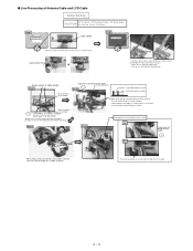
Insert all of antenna cables into the notch of the board. Pass the Cable through the groove. Note: Running over affects the waterproof performance.. Black/White Blue/Gray Brown LCD UNIT Set to the Top Case Assy A LCD Cable Insert Position Order of fixing Screw Screw Screw Screw Screw Screw Screw Screw Close the LCD hooking the Hinge on the Cable. ■ Assembly of Display Unit Details of "A" Safety Working Note Avoid any stress on the Top Case, and then fold back.
Insert all of antenna cables into the notch of the board. Pass the Cable through the groove. Note: Running over affects the waterproof performance.. Black/White Blue/Gray Brown LCD UNIT Set to the Top Case Assy A LCD Cable Insert Position Order of fixing Screw Screw Screw Screw Screw Screw Screw Screw Close the LCD hooking the Hinge on the Cable. ■ Assembly of Display Unit Details of "A" Safety Working Note Avoid any stress on the Top Case, and then fold back.
