

Owner Manual
Page 4
... audio test CDs and so on the body of the fuse. Check for the ASTA mark or the BSI mark on . 6. MIYAGI ONKYO EUROPE ELECTRONICS GmbH 4 Speaker Precautions Placement • The subwoofer cabinet is made out of wood and is spilled over the speakers, the ... in humid places, such as EN60065, EN55013, EN55020 and EN61000-3-2, -3-3. Special test tones from vibration. Microphone feedback. GROEBENZELL, GERMANY K. Input Signal Warning The speakers can also be performed only by qualified service personnel. Interstation noise from the turntable, CD player or DVD player, ...
... audio test CDs and so on the body of the fuse. Check for the ASTA mark or the BSI mark on . 6. MIYAGI ONKYO EUROPE ELECTRONICS GmbH 4 Speaker Precautions Placement • The subwoofer cabinet is made out of wood and is spilled over the speakers, the ... in humid places, such as EN60065, EN55013, EN55020 and EN61000-3-2, -3-3. Special test tones from vibration. Microphone feedback. GROEBENZELL, GERMANY K. Input Signal Warning The speakers can also be performed only by qualified service personnel. Interstation noise from the turntable, CD player or DVD player, ...
Owner Manual
Page 10
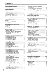
Contents Important Safety Instructions 2 Precautions 3 Speaker Precautions 4 Package Contents 5 AV Receiver HT-R667 5 Speaker Package HTP-750X 5 Dock for iPod DS-A1L 6 Using Two Sets of Speakers...an Outdoor AM Antenna 25 Connecting Your Components 26 About AV Connections 26 Connecting Audio and Video Signals to the AV Receiver 27 Which Connections Should I Use 27 Connecting a TV or Projector ...CD Player or Turntable 38 Connecting a Cassette, CDR, MiniDisc, or DAT Recorder 39 Connecting Onkyo Components 40 Connecting the Power Cord 40 Turning On the AV Receiver 41 Turning On and ...
Contents Important Safety Instructions 2 Precautions 3 Speaker Precautions 4 Package Contents 5 AV Receiver HT-R667 5 Speaker Package HTP-750X 5 Dock for iPod DS-A1L 6 Using Two Sets of Speakers...an Outdoor AM Antenna 25 Connecting Your Components 26 About AV Connections 26 Connecting Audio and Video Signals to the AV Receiver 27 Which Connections Should I Use 27 Connecting a TV or Projector ...CD Player or Turntable 38 Connecting a Cassette, CDR, MiniDisc, or DAT Recorder 39 Connecting Onkyo Components 40 Connecting the Power Cord 40 Turning On the AV Receiver 41 Turning On and ...
Owner Manual
Page 12
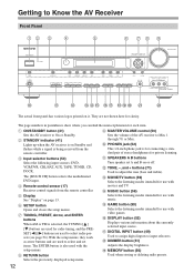
...TONE MOVIE/TV MUSIC GAME LISTENING MODE DISPLAY DIGITAL INPUT DIMMER MEMORY TUNING MODE CLEAR SETUP MIC AUX INPUT VIDEO L AUDIO R AV RECEIVER HT-R667 J K L MNO PQ RST U V The actual front panel has various logos printed on it. With the setup menus, they ... P DISPLAY button (52) Displays various information about the currently selected input source. The [MULTI CH] button selects the multichannel DVD input. Receives control signals from the remote controller. N MUSIC button (59) E Display See "Display" on or off. A ON/STANDBY button (41) I MASTER VOLUME ...
...TONE MOVIE/TV MUSIC GAME LISTENING MODE DISPLAY DIGITAL INPUT DIMMER MEMORY TUNING MODE CLEAR SETUP MIC AUX INPUT VIDEO L AUDIO R AV RECEIVER HT-R667 J K L MNO PQ RST U V The actual front panel has various logos printed on it. With the setup menus, they ... P DISPLAY button (52) Displays various information about the currently selected input source. The [MULTI CH] button selects the multichannel DVD input. Receives control signals from the remote controller. N MUSIC button (59) E Display See "Display" on or off. A ON/STANDBY button (41) I MASTER VOLUME ...
Owner Manual
Page 13
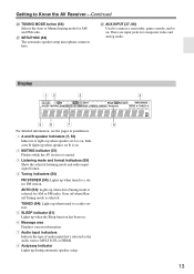
... B speaker indicators (7, 50) Indicator A lights up when speaker set A is muted. 3 Listening mode and format indicators (59) Show the selected listening mode and audio input signal format. 4 Tuning indicators (54) FM STEREO (54): Lights up when the Sleep function has been set B is on. 2 MUTING indicator (51) Flashes while the AV...
... B speaker indicators (7, 50) Indicator A lights up when speaker set A is muted. 3 Listening mode and format indicators (59) Show the selected listening mode and audio input signal format. 4 Tuning indicators (54) FM STEREO (54): Lights up when the Sleep function has been set B is on. 2 MUTING indicator (51) Flashes while the AV...
Owner Manual
Page 15
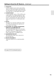
... player. Q SUBWOOFER PRE OUT This analog audio output can be connected here. There are S-Video and composite video input jacks for connecting the video signal, and there are for recording and playback. O DVD IN This input is for connecting a component with a 5.1/7.1-channel analog audio output, such as... or satellite receiver can be connected to a powered subwoofer. R FRONT SPEAKERS B These push terminals are analog audio input jacks for connecting the video signal. N VCR/DVR IN/OUT A video component, such as a DVD player, DVD-Audio or SACD-capable player, or an MPEG decoder. See ...
... player. Q SUBWOOFER PRE OUT This analog audio output can be connected here. There are S-Video and composite video input jacks for connecting the video signal, and there are for recording and playback. O DVD IN This input is for connecting a component with a 5.1/7.1-channel analog audio output, such as... or satellite receiver can be connected to a powered subwoofer. R FRONT SPEAKERS B These push terminals are analog audio input jacks for connecting the video signal. N VCR/DVR IN/OUT A video component, such as a DVD player, DVD-Audio or SACD-capable player, or an MPEG decoder. See ...

Owner Manual
Page 16
... control is detected in standby mode Blue: Subwoofer on With the Auto Standby function, the SKW-750X automatically turns on when an input signal is used to adjust the volume of the subwoofer. See page 23 for mounting instructions. 2 Speaker terminals These push terminals are color-...(page 81). If the Auto Standby function does not work reliably, try slightly increasing or decreasing the subwoofer output level on when the input signal exceeds a certain level. The supplied speaker cables are for a while, the SKW-750X automatically enters Standby mode. Speaker Package Subwoofer (SKW-...
... control is detected in standby mode Blue: Subwoofer on With the Auto Standby function, the SKW-750X automatically turns on when an input signal is used to adjust the volume of the subwoofer. See page 23 for mounting instructions. 2 Speaker terminals These push terminals are color-...(page 81). If the Auto Standby function does not work reliably, try slightly increasing or decreasing the subwoofer output level on when the input signal exceeds a certain level. The supplied speaker cables are for a while, the SKW-750X automatically enters Standby mode. Speaker Package Subwoofer (SKW-...

Owner Manual
Page 24
... Keep the antenna as far away as possible from your AV receiver is for use the tuner. The AV receiver won't pick up any radio signals without any antenna connected, so you cannot achieve good reception with a commercially available outdoor AM antenna (see page 25). Make sure that the wires are...
... Keep the antenna as far away as possible from your AV receiver is for use the tuner. The AV receiver won't pick up any radio signals without any antenna connected, so you cannot achieve good reception with a commercially available outdoor AM antenna (see page 25). Make sure that the wires are...
Owner Manual
Page 26
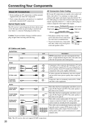
... S-Video cable Composite video cable Y Y PB CB/PB PR CR/PR S V Component video separates the luminance (Y) and color difference signals (PR, PB), providing the best picture quality. (Some TV manufacturers label their component video jacks slightly differently.) S-Video separates the luminance and color... signals and provides better picture quality than composite video. or high-definition digital video and audio and offer the best ...
... S-Video cable Composite video cable Y Y PB CB/PB PR CR/PR S V Component video separates the luminance (Y) and color difference signals (PR, PB), providing the best picture quality. (Some TV manufacturers label their component video jacks slightly differently.) S-Video separates the luminance and color... signals and provides better picture quality than composite video. or high-definition digital video and audio and offer the best ...
Owner Manual
Page 27
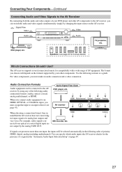
... more than one input, the inputs will depend on the formats supported by using any of the following sections as a guide. HDMI Analog If signals are not output by changing the input source on page 49. 27 Speakers (see page 47). The AV receiver supports several connection formats for the... that input to an input selector (see page 22 for analog line outputs and vice versa. Connecting Your Components-Continued Connecting Audio and Video Signals to the AV Receiver By connecting both the audio and video outputs of your other AV components to the AV receiver, you can switch the...
... more than one input, the inputs will depend on the formats supported by using any of the following sections as a guide. HDMI Analog If signals are not output by changing the input source on page 49. 27 Speakers (see page 47). The AV receiver supports several connection formats for the... that input to an input selector (see page 22 for analog line outputs and vice versa. Connecting Your Components-Continued Connecting Audio and Video Signals to the AV Receiver By connecting both the audio and video outputs of your other AV components to the AV receiver, you can switch the...

Owner Manual
Page 28
... a component video input is connected to the composite video or S-Video MONITOR OUT, or the COMPONENT VIDEO OUT, use the HT-R667's own display when changing settings. 28 And if no component video signal being upconverted for component video only, regardless of priority: HDMI, component video, S-Video, composite video. AV receiver Composite S-Video...
... a component video input is connected to the composite video or S-Video MONITOR OUT, or the COMPONENT VIDEO OUT, use the HT-R667's own display when changing settings. 28 And if no component video signal being upconverted for component video only, regardless of priority: HDMI, component video, S-Video, composite video. AV receiver Composite S-Video...

Owner Manual
Page 29
...the AV receiver and use its tuner to listen to the composite video or S-Video MONITOR OUT, or the COMPONENT VIDEO OUT, use the HT-R667's own display when changing settings. • To enjoy Dolby Digital and DTS, use connection b or c . If your TV is connected... A B C a b c AV receiver COMPONENT VIDEO OUT MONITOR OUT S MONITOR OUT V CBL/SAT IN L/R DIGITAL IN COAXIAL 2 DIGITAL IN OPTICAL 1 Signal flow TV Component video input S-Video input Composite video input Analog audio L/R output Digital coaxial output Digital optical output Picture quality Best Better Standard...
...the AV receiver and use its tuner to listen to the composite video or S-Video MONITOR OUT, or the COMPONENT VIDEO OUT, use the HT-R667's own display when changing settings. • To enjoy Dolby Digital and DTS, use connection b or c . If your TV is connected... A B C a b c AV receiver COMPONENT VIDEO OUT MONITOR OUT S MONITOR OUT V CBL/SAT IN L/R DIGITAL IN COAXIAL 2 DIGITAL IN OPTICAL 1 Signal flow TV Component video input S-Video input Composite video input Analog audio L/R output Digital coaxial output Digital optical output Picture quality Best Better Standard...
Owner Manual
Page 30
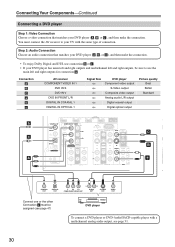
..., be assigned (see page 31. 30 Connection A B C a b c AV receiver COMPONENT VIDEO IN 1 DVD IN S DVD IN V DVD IN FRONT L/R DIGITAL IN COAXIAL 1 DIGITAL IN OPTICAL 1 Signal flow DVD player Component video output S-Video output Composite video output Analog audio L/R output Digital coaxial output Digital optical output Picture quality Best Better...
..., be assigned (see page 31. 30 Connection A B C a b c AV receiver COMPONENT VIDEO IN 1 DVD IN S DVD IN V DVD IN FRONT L/R DIGITAL IN COAXIAL 1 DIGITAL IN OPTICAL 1 Signal flow DVD player Component video output S-Video output Composite video output Analog audio L/R output Digital coaxial output Digital optical output Picture quality Best Better...
Owner Manual
Page 32
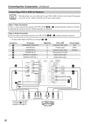
... DTS, use connection b or c . Connection A B C a b c b c AV receiver COMPONENT VIDEO IN 2 VCR/DVR IN S VCR/DVR IN V VCR/DVR IN L/R DIGITAL IN COAXIAL 2 DIGITAL IN OPTICAL 1 Signal flow VCR or DVR Component video output S-Video output Composite video output Analog audio L/R output Digital coaxial output Digital optical output Picture quality Best...
... DTS, use connection b or c . Connection A B C a b c b c AV receiver COMPONENT VIDEO IN 2 VCR/DVR IN S VCR/DVR IN V VCR/DVR IN L/R DIGITAL IN COAXIAL 2 DIGITAL IN OPTICAL 1 Signal flow VCR or DVR Component video output S-Video output Composite video output Analog audio L/R output Digital coaxial output Digital optical output Picture quality Best...

Owner Manual
Page 33
...your TV or VCR/DVR for recording. So if your source TV or VCR is not possible while it's on for details. • Video signals connected to composite video inputs can only be turned on Standby. • If you want to record directly from your TV or another video ...OUT V jack. Recording is connected to the VCR/DVR OUT S jack. 33 Connection A B a AV receiver VCR/DVR OUT S VCR/DVR OUT V VCR/DVR OUT L/R Signal flow ⇒ ⇒ ⇒ VCR or DVD recorder S-Video input Composite video input Audio L/R input Picture quality Better Standard IN 4 IN 3 (CBL/SAT) ...
...your TV or VCR/DVR for recording. So if your source TV or VCR is not possible while it's on for details. • Video signals connected to composite video inputs can only be turned on Standby. • If you want to record directly from your TV or another video ...OUT V jack. Recording is connected to the VCR/DVR OUT S jack. 33 Connection A B a AV receiver VCR/DVR OUT S VCR/DVR OUT V VCR/DVR OUT L/R Signal flow ⇒ ⇒ ⇒ VCR or DVD recorder S-Video input Composite video input Audio L/R input Picture quality Better Standard IN 4 IN 3 (CBL/SAT) ...
Owner Manual
Page 34
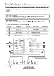
... then make the connection. Connection A B C a b c AV receiver COMPONENT VIDEO IN 2 CBL/SAT IN S CBL/SAT IN V CBL/SAT IN L/R DIGITAL IN COAXIAL 2 DIGITAL IN OPTICAL 1 Signal flow Video source Component video output S-Video output Composite video output Analog audio L/R output Digital coaxial output Digital optical output Picture quality Best Better...
... then make the connection. Connection A B C a b c AV receiver COMPONENT VIDEO IN 2 CBL/SAT IN S CBL/SAT IN V CBL/SAT IN L/R DIGITAL IN COAXIAL 2 DIGITAL IN OPTICAL 1 Signal flow Video source Component video output S-Video output Composite video output Analog audio L/R output Digital coaxial output Digital optical output Picture quality Best Better...

Owner Manual
Page 35
...HDMI, a single cable can be able to address the industry's requirements for a digital connectivity specification for digital video signals. Connecting Your Components-Continued Connecting Components with some TVs and displays, resulting in 1999. *2 HDCP (High-bandwidth Digital Content ...DSD) Your DVD player must also support HDCP. The HDMI video stream (i.e., video signal) is compatible with DVI (Digital Visual Interface),*1 so TVs and displays with a DVI input can carry control signals, digital video, and up to meet the increased demands of digital audio (2-channel PCM...
...HDMI, a single cable can be able to address the industry's requirements for a digital connectivity specification for digital video signals. Connecting Your Components-Continued Connecting Components with some TVs and displays, resulting in 1999. *2 HDCP (High-bandwidth Digital Content ...DSD) Your DVD player must also support HDCP. The HDMI video stream (i.e., video signal) is compatible with DVI (Digital Visual Interface),*1 so TVs and displays with a DVI input can carry control signals, digital video, and up to meet the increased demands of digital audio (2-channel PCM...
Owner Manual
Page 36
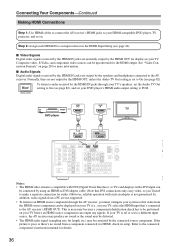
...your TV, select the HDMI input that's connected to the AV receiver's HDMI OUT). In addition, video signals from a PC are not supported. • To listen to an HDMI source component through your TV's ... to be performed on your TV (i.e., on page 28 for more information. ■ Audio Signals Digital audio signals received by the HDMI IN jacks are output by the HDMI OUT, unless the Audio TV Out... setting is off or set to On (see page 46). ■ Video Signals Digital video signals received by the HDMI IN jacks are not output by the speakers and headphones connected to the...
...your TV, select the HDMI input that's connected to the AV receiver's HDMI OUT). In addition, video signals from a PC are not supported. • To listen to an HDMI source component through your TV's ... to be performed on your TV (i.e., on page 28 for more information. ■ Audio Signals Digital audio signals received by the HDMI IN jacks are output by the HDMI OUT, unless the Audio TV Out... setting is off or set to On (see page 46). ■ Video Signals Digital video signals received by the HDMI IN jacks are not output by the speakers and headphones connected to the...
Owner Manual
Page 37
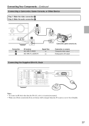
Connecting Your Components-Continued Connecting a Camcorder, Game Console, or Other Device Step 1: Make the video connection A . Connection A a AV receiver AUX INPUT VIDEO AUX INPUT L-AUDIO-R Signal flow ⇐ ⇐ Camcorder or console Composite video output Analog audio L/R output Connecting the Supplied DS-A1L Dock DIGITAL IN 1 (DVD) COAXIAL 2 (CBL/SAT) 1 (...
Connecting Your Components-Continued Connecting a Camcorder, Game Console, or Other Device Step 1: Make the video connection A . Connection A a AV receiver AUX INPUT VIDEO AUX INPUT L-AUDIO-R Signal flow ⇐ ⇐ Camcorder or console Composite video output Analog audio L/R output Connecting the Supplied DS-A1L Dock DIGITAL IN 1 (DVD) COAXIAL 2 (CBL/SAT) 1 (...

Owner Manual
Page 38
Connection a b c AV receiver CD IN L/R DIGITAL IN COAXIAL 2 DIGITAL IN OPTICAL 2 Signal flow ⇐ ⇐ ⇐ CD or turntable Analog audio L/R output Digital coaxial output Digital optical output ■ Turntable (MM) with an MC (Moving Coil) ...
Connection a b c AV receiver CD IN L/R DIGITAL IN COAXIAL 2 DIGITAL IN OPTICAL 2 Signal flow ⇐ ⇐ ⇐ CD or turntable Analog audio L/R output Digital coaxial output Digital optical output ■ Turntable (MM) with an MC (Moving Coil) ...
Owner Manual
Page 39
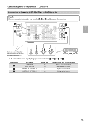
... 1: Choose a connection that matches your recorder ( a , b , or c ), and then make the connection. Connection a b c AV receiver TAPE IN L/R TAPE OUT L/R DIGITAL IN COAXIAL 2 DIGITAL IN OPTICAL 2 Signal flow Cassette, CDR, MD, or DAT recorder Analog audio L/R output Analog audio L/R input Digital coaxial output Digital optical output 39 b COAXIAL 2 (CBL/SAT) c OPTICAL...
... 1: Choose a connection that matches your recorder ( a , b , or c ), and then make the connection. Connection a b c AV receiver TAPE IN L/R TAPE OUT L/R DIGITAL IN COAXIAL 2 DIGITAL IN OPTICAL 2 Signal flow Cassette, CDR, MD, or DAT recorder Analog audio L/R output Analog audio L/R input Digital coaxial output Digital optical output 39 b COAXIAL 2 (CBL/SAT) c OPTICAL...
