
English Manual
Page 2
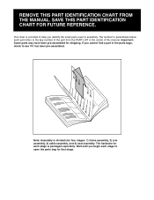
TABLE OF CONTENTS IMPORTANT PRECAUTIONS 3 BEFORE YOU BEGIN 4 ASSEMBLY 5 CABLE DIAGRAM 21 ADJUSTMENTS 22 WEIGHT RESISTANCE CHART 24 TROUBLE-SHOOTING AND MAINTENANCE 25 EXERCISE GUIDELINES 26 ORDERING REPLACEMENT PARTS Back Cover LIMITED WARRANTY Back Cover Note: A PART IDENTIFICATION CHART and a PART LIST/EXPLODED DRAWING are attached in the center of ICON Health & Fitness, Inc. 2 NordicTrack is a registered trademark of this manual. Remove the PART IDENTIFICATION CHART and PART LIST/EXPLODED DRAWING before beginning assembly.
TABLE OF CONTENTS IMPORTANT PRECAUTIONS 3 BEFORE YOU BEGIN 4 ASSEMBLY 5 CABLE DIAGRAM 21 ADJUSTMENTS 22 WEIGHT RESISTANCE CHART 24 TROUBLE-SHOOTING AND MAINTENANCE 25 EXERCISE GUIDELINES 26 ORDERING REPLACEMENT PARTS Back Cover LIMITED WARRANTY Back Cover Note: A PART IDENTIFICATION CHART and a PART LIST/EXPLODED DRAWING are attached in the center of ICON Health & Fitness, Inc. 2 NordicTrack is a registered trademark of this manual. Remove the PART IDENTIFICATION CHART and PART LIST/EXPLODED DRAWING before beginning assembly.
English Manual
Page 3
...the floor or carpet beneath the weight system to order a free replacement decal. Replace any exercise program, consult your physician. Make sure the cables remain on the pulleys at all instructions before using the weight system. 1. Keep hands and feet away from the weight system when performing an ...is missing or illegible, please call our Customer Service Department toll-free at any time while exercising, stop immediately and make sure the cables are adequately informed of the pulleys. 13. The warning decals shown here have been placed in two locations each time you use ...
...the floor or carpet beneath the weight system to order a free replacement decal. Replace any exercise program, consult your physician. Make sure the cables remain on the pulleys at all instructions before using the weight system. 1. Keep hands and feet away from the weight system when performing an ...is missing or illegible, please call our Customer Service Department toll-free at any time while exercising, stop immediately and make sure the cables are adequately informed of the pulleys. 13. The warning decals shown here have been placed in two locations each time you use ...
English Manual
Page 5
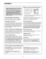
... press arm, leg lever, handles, and leg press. until assembly is enough room to walk around the weight system as you will attach the cables and pulleys that the weight system can be assembled successfully by anyone. The Four Stages of the Assembly Process Frame Assembly-You will begin each... read the information on the floor and use it to the many features of the weight system in a cleared area and remove the packing materials. Cable Assembly-During this page; Note: Assembly will be more time than it takes to do otherwise. You may have a socket set, a set of open ...
... press arm, leg lever, handles, and leg press. until assembly is enough room to walk around the weight system as you will attach the cables and pulleys that the weight system can be assembled successfully by anyone. The Four Stages of the Assembly Process Frame Assembly-You will begin each... read the information on the floor and use it to the many features of the weight system in a cleared area and remove the packing materials. Cable Assembly-During this page; Note: Assembly will be more time than it takes to do otherwise. You may have a socket set, a set of open ...
English Manual
Page 11
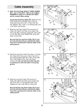
... (44) to the Rear Leg Press Upright (97) with a 3/8" x 3 3/4" Bolt (92), a 3/8" Washer (55), and a 3/8" Nylon Locknut (50). Refer to the CABLE DIAGRAM on page 21 to hold the Cable in the pulley groove. 16 45 17 84 55 63 76 90 55 97 92 35 44 76 50 55 18. Open the... parts bags labeled "CABLE ASSEMBLY" and "4 PULLEYS." Attach the Pulley and a Cable Trap (44) to the Leg Press Base (84) with a 3/8" x 3 3/4" Bolt (92), a 3/8" Washer (55), and a 3/8" Nylon Locknut (50). Be sure that the...
... (44) to the Rear Leg Press Upright (97) with a 3/8" x 3 3/4" Bolt (92), a 3/8" Washer (55), and a 3/8" Nylon Locknut (50). Refer to the CABLE DIAGRAM on page 21 to hold the Cable in the pulley groove. 16 45 17 84 55 63 76 90 55 97 92 35 44 76 50 55 18. Open the... parts bags labeled "CABLE ASSEMBLY" and "4 PULLEYS." Attach the Pulley and a Cable Trap (44) to the Leg Press Base (84) with a 3/8" x 3 3/4" Bolt (92), a 3/8" Washer (55), and a 3/8" Nylon Locknut (50). Be sure that the...

English Manual
Page 12
... a 3/8" Washer (55) and a 5/8" x 1/2" Bushing (42) onto a 3/8" x 2 1/2" Bolt (54). Wrap the Leg Press Cable (76) around a 4" Pulley (35). Attach the Pulley and a Cable Trap (44) to the bracket on the Stabilizer (5) with a 1/4" Washer (71) and a 1/4" Nylon Locknut (25). 20. Remove the...from the Pulley Bracket (91). Insert the 3/8" x 2 1/2" Bolt (54) through the slot. Lay the Pulley Bracket (91) and the Leg Press Cable (76) aside; Wrap the High Cable (73) around a 4" 20 Pulley (35). Slide another 5/8" x 1/2" Bushing (42) and 3/8" Washer (55) onto the 3/8" x 2 1/2" Bolt...
... a 3/8" Washer (55) and a 5/8" x 1/2" Bushing (42) onto a 3/8" x 2 1/2" Bolt (54). Wrap the Leg Press Cable (76) around a 4" Pulley (35). Attach the Pulley and a Cable Trap (44) to the bracket on the Stabilizer (5) with a 1/4" Washer (71) and a 1/4" Nylon Locknut (25). 20. Remove the...from the Pulley Bracket (91). Insert the 3/8" x 2 1/2" Bolt (54) through the slot. Lay the Pulley Bracket (91) and the Leg Press Cable (76) aside; Wrap the High Cable (73) around a 4" 20 Pulley (35). Slide another 5/8" x 1/2" Bushing (42) and 3/8" Washer (55) onto the 3/8" x 2 1/2" Bolt...
English Manual
Page 13
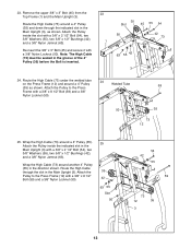
...Press Frame (12) with a 3/8" x 2 1/2" Bolt (54), two 3/8" Washers (55), two 5/8" x 1/2" Bushings (42), and a 3/8" Nylon Jamnut (63). Wrap the High Cable (73) around a 4" Pulley Welded Tube 59 (35) as shown. Remove the upper 3/8" x 3" Bolt (45) from the Top Frame (1) and the Main Upright (3). Attach the ...Frame with a 3/8" x 2 1/2" Bolt (54), two 3/8" Washers (55), two 5/8" x 1/2" Bushings (42), and a 3/8" Nylon Jamnut (63). 23. Route the High Cable (73) under the welded tube 24 on the Press Frame (12) and around another 4" Pulley (35) in the groove of the 4" Pulley (35) before the...
...Press Frame (12) with a 3/8" x 2 1/2" Bolt (54), two 3/8" Washers (55), two 5/8" x 1/2" Bushings (42), and a 3/8" Nylon Jamnut (63). Wrap the High Cable (73) around a 4" Pulley Welded Tube 59 (35) as shown. Remove the upper 3/8" x 3" Bolt (45) from the Top Frame (1) and the Main Upright (3). Attach the ...Frame with a 3/8" x 2 1/2" Bolt (54), two 3/8" Washers (55), two 5/8" x 1/2" Bushings (42), and a 3/8" Nylon Jamnut (63). 23. Route the High Cable (73) under the welded tube 24 on the Press Frame (12) and around another 4" Pulley (35) in the groove of the 4" Pulley (35) before the...
English Manual
Page 14
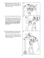
...a 4" Pulley (35), and back down through the indicated slot in the Top Frame (1) with a 3/8" x 1 3/4" Bolt (60) and a 3/8" Nylon Jamnut (63). Make sure the Cable is oriented to the top set of holes in the Main Upright (3) with a 3/8" x 2 1/2" Bolt (54), two 3/8" Washers (55), two 5/8" x 1/2" Bushings (42), and a ...3/8" Nylon Jamnut (63). 3 35 73 63 42 55 54 42 55 27. Route the High Cable (73) up through the Top Frame. Attach the 4" Pulley (35) inside the slot in the end of the Pulley and that the...
...a 4" Pulley (35), and back down through the indicated slot in the Top Frame (1) with a 3/8" x 1 3/4" Bolt (60) and a 3/8" Nylon Jamnut (63). Make sure the Cable is oriented to the top set of holes in the Main Upright (3) with a 3/8" x 2 1/2" Bolt (54), two 3/8" Washers (55), two 5/8" x 1/2" Bushings (42), and a ...3/8" Nylon Jamnut (63). 3 35 73 63 42 55 54 42 55 27. Route the High Cable (73) up through the Top Frame. Attach the 4" Pulley (35) inside the slot in the end of the Pulley and that the...
English Manual
Page 15
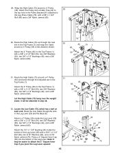
... attached to the Top Frame (1) with a 3/8" x 1 3/4" Bolt (60) and a 3/8" Nylon Jamnut (63). 35 30. Attach the 4" Pulley (35) to the Leg Press Cable (76), with a 3/8" x 2 1/2" Bolt (54), two 3/8" Washers (55), two 5/8" x 1/2" Bushings (42), and a 3/8" Nylon Jamnut (63). Note: It may be ...attached in the Leg Lever (29) and the Base (8). 32 Attach a 4" Pulley (35) inside the bottom of the Leg Lever. Route the Low Cable through the indicated slot in the direction shown. Attach the 1/2" x 1 3/4" Bushing (94) inside the Leg Lever (29) with a 3/8" x 2 1/2" Bolt ...
... attached to the Top Frame (1) with a 3/8" x 1 3/4" Bolt (60) and a 3/8" Nylon Jamnut (63). 35 30. Attach the 4" Pulley (35) to the Leg Press Cable (76), with a 3/8" x 2 1/2" Bolt (54), two 3/8" Washers (55), two 5/8" x 1/2" Bushings (42), and a 3/8" Nylon Jamnut (63). Note: It may be ...attached in the Leg Lever (29) and the Base (8). 32 Attach a 4" Pulley (35) inside the bottom of the Leg Lever. Route the Low Cable through the indicated slot in the direction shown. Attach the 1/2" x 1 3/4" Bushing (94) inside the Leg Lever (29) with a 3/8" x 2 1/2" Bolt ...
English Manual
Page 16
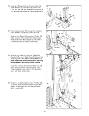
...x 2 1/2" Bolt (54), two 3/8" Washers (55), two 5/8" x 1/2" Bushings (42), and a 3/8" Nylon Jamnut (63). 8 72 35 34. Make sure the Cable is oriented so it will hold the Cable in the groove of the Base (8) with a 3/8" x 2" Bolt (62) and a 3/8" Nylon Locknut (50). 72 35 62 3 50 16 Attach the 4" Pulley... 2" Bolt (62) and a 3/8" Nylon Locknut (50). 63 42 55 34 50 35 62 72 Bracket 55 54 42 3 Slot 35. Wrap the Low Cable (72) over the Low Cable (72), 33 inside the bracket on the Main Upright (3) with a 3/8" x 1 3/4" Bolt (60) and a 3/8" Nylon Jamnut (63). 8 31 60 ...
...x 2 1/2" Bolt (54), two 3/8" Washers (55), two 5/8" x 1/2" Bushings (42), and a 3/8" Nylon Jamnut (63). 8 72 35 34. Make sure the Cable is oriented so it will hold the Cable in the groove of the Base (8) with a 3/8" x 2" Bolt (62) and a 3/8" Nylon Locknut (50). 72 35 62 3 50 16 Attach the 4" Pulley... 2" Bolt (62) and a 3/8" Nylon Locknut (50). 63 42 55 34 50 35 62 72 Bracket 55 54 42 3 Slot 35. Wrap the Low Cable (72) over the Low Cable (72), 33 inside the bracket on the Main Upright (3) with a 3/8" x 1 3/4" Bolt (60) and a 3/8" Nylon Jamnut (63). 8 31 60 ...
English Manual
Page 17
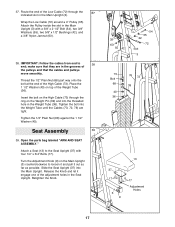
... possible. 37. Tighten the bolt into the Main Upright. Slide the Seat Upright (37) into the Weight Tube until the Cables (73, 72, 76) are in the Weight Tube (36). Seat Assembly 39 39. Attach a Seat (13) to ... 40 36 76 72 39 13 37 17 3 9 17 Adjustment Holes 17 IMPORTANT: Follow the cables from end to loosen it and pull it engage one of the Weight Tube (36). make sure... that they are tight. Insert the bolt on the High Cable (73) through the 37 indicated slot in the Seat Upright. Tighten the 1/2" Plain Nut (68) against...
... possible. 37. Tighten the bolt into the Main Upright. Slide the Seat Upright (37) into the Weight Tube until the Cables (73, 72, 76) are in the Weight Tube (36). Seat Assembly 39 39. Attach a Seat (13) to ... 40 36 76 72 39 13 37 17 3 9 17 Adjustment Holes 17 IMPORTANT: Follow the cables from end to loosen it and pull it engage one of the Weight Tube (36). make sure... that they are tight. Insert the bolt on the High Cable (73) through the 37 indicated slot in the Seat Upright. Tighten the 1/2" Plain Nut (68) against...
English Manual
Page 20
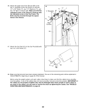
...(71), and two 1/4" Nylon Locknuts (25). The use of the Top Frame. Before using the weight system, pull each cable a few times to the two "L"-brackets on page 25. 20 If one of this manual. Attach the upper end of ... to make sure that the indicated corner of the Shroud is any slack in the cables, you will be explained in the Shroud. 46 71 17 1 "L"-Brackets 25 71 17 Align Corners ...56 47. Make sure that the cables move smoothly, find and correct the problem. See TROUBLESHOOTING AND MAINTENANCE on the Top Frame (1) with 47...
...(71), and two 1/4" Nylon Locknuts (25). The use of the Top Frame. Before using the weight system, pull each cable a few times to the two "L"-brackets on page 25. 20 If one of this manual. Attach the upper end of ... to make sure that the indicated corner of the Shroud is any slack in the cables, you will be explained in the Shroud. 46 71 17 1 "L"-Brackets 25 71 17 Align Corners ...56 47. Make sure that the cables move smoothly, find and correct the problem. See TROUBLESHOOTING AND MAINTENANCE on the Top Frame (1) with 47...

English Manual
Page 21
CABLE DIAGRAM The diagram below shows the proper routing of the Low Cable (72), the High Cable (73), and the Leg Press Cable (76). Incorrect cable routing can damage the weight system. 8 10 11 2 1 High Cable (73) 9 6 7 4 3 5 64 6 12 4 3 Leg Press Cable (76) Cable ID Chart 53 5 1 -76 -72 -73 21 2 2 1 Low Cable (72) Large Ball Make sure that the cables are routed correctly, that the pulleys move smoothly, and that the cable traps do not touch or bind the cables. The numbers show the correct route for each cable.
CABLE DIAGRAM The diagram below shows the proper routing of the Low Cable (72), the High Cable (73), and the Leg Press Cable (76). Incorrect cable routing can damage the weight system. 8 10 11 2 1 High Cable (73) 9 6 7 4 3 5 64 6 12 4 3 Leg Press Cable (76) Cable ID Chart 53 5 1 -76 -72 -73 21 2 2 1 Low Cable (72) Large Ball Make sure that the cables are routed correctly, that the pulleys move smoothly, and that the cable traps do not touch or bind the cables. The numbers show the correct route for each cable.
English Manual
Page 22
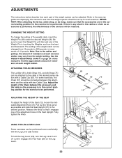
...CHART on the Leg Lever. 13 9 37 29 11 28 22 For some exercises, the Chain (67) should be connected between the accessory and the cable so the accessory is any slack in increments of 10 pounds. Fully tighten the Knob. Refer to the exercise guide accompanying this manual to find... the approximate amount of resistance at each exercise station may vary from 10 pounds to 200 pounds, in the cables or chain as possible and slide the Seat Upright (37) to the desired position. CHANGING THE WEIGHT SETTING To change the setting of the exercise...
...CHART on the Leg Lever. 13 9 37 29 11 28 22 For some exercises, the Chain (67) should be connected between the accessory and the cable so the accessory is any slack in increments of 10 pounds. Fully tighten the Knob. Refer to the exercise guide accompanying this manual to find... the approximate amount of resistance at each exercise station may vary from 10 pounds to 200 pounds, in the cables or chain as possible and slide the Seat Upright (37) to the desired position. CHANGING THE WEIGHT SETTING To change the setting of the exercise...

English Manual
Page 24
Note: The actual resistance at each station may vary due to differences in individual weight plates as well as friction between the cables, pulleys, and weight guides. top weight. The other numbers refer to the 10 lb. WEIGHT RESISTANCE CHART This chart shows the approximate weight resistance at ...
Note: The actual resistance at each station may vary due to differences in individual weight plates as well as friction between the cables, pulleys, and weight guides. top weight. The other numbers refer to the 10 lb. WEIGHT RESISTANCE CHART This chart shows the approximate weight resistance at ...
English Manual
Page 25
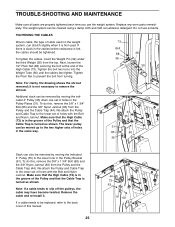
..., the drawing shows the shroud removed; it is turned as shown. Note: If a cable tends to remove the shroud. If a cable needs to be moved up to the two higher sets of holes in the same way....to the lower set of this manual. 25 35 44 73 63 91 60 Re-attach the Pulley and Cable Trap to prevent the bolt from the top. Next, loosen the 1/2" Plain Nut (68) securing the...end of holes with the Bolt and Nylon Jamnut. Make sure that the Cable Trap is not necessary to slip off the pulleys, the cable may have become twisted. Replace any worn parts immediately. TROUBLE-SHOOTING AND ...
..., the drawing shows the shroud removed; it is turned as shown. Note: If a cable tends to remove the shroud. If a cable needs to be moved up to the two higher sets of holes in the same way....to the lower set of this manual. 25 35 44 73 63 91 60 Re-attach the Pulley and Cable Trap to prevent the bolt from the top. Next, loosen the 1/2" Plain Nut (68) securing the...end of holes with the Bolt and Nylon Jamnut. Make sure that the Cable Trap is not necessary to slip off the pulleys, the cable may have become twisted. Replace any worn parts immediately. TROUBLE-SHOOTING AND ...
English Manual
Page 29
... parts bag for that stage. Note: Assembly is packaged separately. Wait until you begin each stage is divided into four stages: 1) frame assembly, 2) arm assembly, 3) cable assembly, and 4) seat assembly. Important: Some parts may have been pre-assembled for shipping.
... parts bag for that stage. Note: Assembly is packaged separately. Wait until you begin each stage is divided into four stages: 1) frame assembly, 2) arm assembly, 3) cable assembly, and 4) seat assembly. Important: Some parts may have been pre-assembled for shipping.

English Manual
Page 34
... x 2" Bolt 3/8" Nylon Jamnut 3/8" x 3" Carriage Bolt 3/8" x 4" Bolt Weight Cover Chain 1/2" Plain Nut Cable Clip Leg Press Backrest 1/4" Washer Low Cable High Cable Sliding Seat Frame Ab Strap Leg Press Cable Weight Insert 5/16" x 3" Bolt 5/16" Nylon Jamnut 5/16" Washer 5/16" Nylon Locknut 3/8" x 5" ...Round Inner Cap 4" Pulley Weight Tube Seat Upright Tinnerman Clip Weight Pin 1 1/2" Washer Backrest 5/8" x 1/2" Pulley Bushing 1/4" x 3 3/4" Carriage Bolt Cable Trap 3/8" x 3" Bolt Right Press/Fly Arm Weight Tube Bumper Large Bushing Left Press/Fly Arm 3/8" Nylon Locknut 3/8" x 9" Bolt 3/8" x ...
... x 2" Bolt 3/8" Nylon Jamnut 3/8" x 3" Carriage Bolt 3/8" x 4" Bolt Weight Cover Chain 1/2" Plain Nut Cable Clip Leg Press Backrest 1/4" Washer Low Cable High Cable Sliding Seat Frame Ab Strap Leg Press Cable Weight Insert 5/16" x 3" Bolt 5/16" Nylon Jamnut 5/16" Washer 5/16" Nylon Locknut 3/8" x 5" ...Round Inner Cap 4" Pulley Weight Tube Seat Upright Tinnerman Clip Weight Pin 1 1/2" Washer Backrest 5/8" x 1/2" Pulley Bushing 1/4" x 3 3/4" Carriage Bolt Cable Trap 3/8" x 3" Bolt Right Press/Fly Arm Weight Tube Bumper Large Bushing Left Press/Fly Arm 3/8" Nylon Locknut 3/8" x 9" Bolt 3/8" x ...


