
English Manual
Page 2
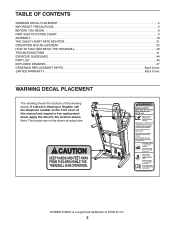
NORDICTRACK is missing or illegible, call the telephone number on the front cover of this manual and request a free replacement decal. If a decal is a registered trademark ... location shown. TABLE OF CONTENTS WARNING DECAL PLACEMENT 2 IMPORTANT PRECAUTIONS 3 BEFORE YOU BEGIN 8 PART IDENTIFICATION CHART 9 ASSEMBLY 10 THE CHEST HEART RATE MONITOR 21 OPERATION AND ADJUSTMENT 22 HOW TO FOLD AND MOVE THE TREADMILL 40 TROUBLESHOOTING 41 EXERCISE GUIDELINES 44 PART LIST 45 EXPLODED DRAWING 47 ORDERING REPLACEMENT PARTS Back Cover...
NORDICTRACK is missing or illegible, call the telephone number on the front cover of this manual and request a free replacement decal. If a decal is a registered trademark ... location shown. TABLE OF CONTENTS WARNING DECAL PLACEMENT 2 IMPORTANT PRECAUTIONS 3 BEFORE YOU BEGIN 8 PART IDENTIFICATION CHART 9 ASSEMBLY 10 THE CHEST HEART RATE MONITOR 21 OPERATION AND ADJUSTMENT 22 HOW TO FOLD AND MOVE THE TREADMILL 40 TROUBLESHOOTING 41 EXERCISE GUIDELINES 44 PART LIST 45 EXPLODED DRAWING 47 ORDERING REPLACEMENT PARTS Back Cover...
English Manual
Page 4
... the storage latch is properly assembled. (See ASSEMBLY on page 10 and HOW TO FOLD AND MOVE THE TREADMILL on the treadmill. 28. If you feel faint or if you experience pain while exercising, stop immediately and cool down. 29. To protect the treadmill and television during lightning storms,...power cord from touching such power lines or circuits, as an exercise aid in determining heart rate trends in the vicinity of the treadmill regularly. Never remove the motor hood unless instructed to grounding electrodes, and requirements for the location of the television. To reduce the...
... the storage latch is properly assembled. (See ASSEMBLY on page 10 and HOW TO FOLD AND MOVE THE TREADMILL on the treadmill. 28. If you feel faint or if you experience pain while exercising, stop immediately and cool down. 29. To protect the treadmill and television during lightning storms,...power cord from touching such power lines or circuits, as an exercise aid in determining heart rate trends in the vicinity of the treadmill regularly. Never remove the motor hood unless instructed to grounding electrodes, and requirements for the location of the television. To reduce the...

English Manual
Page 9
...)–-8 5/16" x 3/4" Screw (1)–-12 5/16" x 1 3/4" Bolt (3)–-1 5/16" x 2 1/4" Bolt (4)–-1 5/16" x 2" Screw (2)–-4 9 The number following the key number is the quantity used for assembly. PART IDENTIFICATION CHART Use the drawings below each drawing is the key number of the part, from the PART LIST near the end of this...
...)–-8 5/16" x 3/4" Screw (1)–-12 5/16" x 1 3/4" Bolt (3)–-1 5/16" x 2 1/4" Bolt (4)–-1 5/16" x 2" Screw (2)–-4 9 The number following the key number is the quantity used for assembly. PART IDENTIFICATION CHART Use the drawings below each drawing is the key number of the part, from the PART LIST near the end of this...

English Manual
Page 10
...your computer and register 1 your product. •• activates your product. 2. If there is an oily substance on the exterior of the treadmill. Attach the left Upright (84) in a cleared area and remove the packing materials. Make sure that the power cord is normal. This is...the left wheel assembly (not shown) to notify you of the packing materials until you do not use power tools. 1. ASSEMBLY •• Assembly requires two persons. •• Place all assembly steps. •• After shipping, there may be an oily substance on the treadmill, wipe it off...
...your computer and register 1 your product. •• activates your product. 2. If there is an oily substance on the exterior of the treadmill. Attach the left Upright (84) in a cleared area and remove the packing materials. Make sure that the power cord is normal. This is...the left wheel assembly (not shown) to notify you of the packing materials until you do not use power tools. 1. ASSEMBLY •• Assembly requires two persons. •• Place all assembly steps. •• After shipping, there may be an oily substance on the treadmill, wipe it off...

English Manual
Page 12
.... Then, remove the Pulse Crossbar (80). 5. Attach the two Handrails (74) to the Upright Crossbar (76) with the Truss Head Screws (24). Set the console assembly (D) face down on a soft surface to pinch the Upright Coaxial Cable C (78), the Upright Wire (83), or the fan wire (B). D E 80 E 12 ...the hole in step 3 and two 5/16" Star Washers 2 (8). Then, remove the tie. Be 8 careful not to avoid scratching the console 7 assembly. Then, remove and discard the two indicated screws (C). 74 78 84 2 74 B 83 8 C 84 7. Remove and discard the four indicated screws (E).
.... Then, remove the Pulse Crossbar (80). 5. Attach the two Handrails (74) to the Upright Crossbar (76) with the Truss Head Screws (24). Set the console assembly (D) face down on a soft surface to pinch the Upright Coaxial Cable C (78), the Upright Wire (83), or the fan wire (B). D E 80 E 12 ...the hole in step 3 and two 5/16" Star Washers 2 (8). Then, remove the tie. Be 8 careful not to avoid scratching the console 7 assembly. Then, remove and discard the two indicated screws (C). 74 78 84 2 74 B 83 8 C 84 7. Remove and discard the four indicated screws (E).

English Manual
Page 13
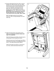
Attach the Pulse Crossbar with two of a second person, hold the console assembly (D) near the Handrails (74). With the help of the 5/16" x 2" Screws (2) that you removed in step 3, two 5/16" 2 Star Washers (8), and two #10 x 3/4" Screws (6). Then, ...
Attach the Pulse Crossbar with two of a second person, hold the console assembly (D) near the Handrails (74). With the help of the 5/16" x 2" Screws (2) that you removed in step 3, two 5/16" 2 Star Washers (8), and two #10 x 3/4" Screws (6). Then, ...

English Manual
Page 14
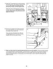
Attach the console assembly (D) to overtighten the Screws. 80 5 5 14 Insert the wires and cables upward into the Pulse Crossbar (80), and then tighten them . Be careful not to ... #8 x 3/4" Screws (5) with four 5/16" x 2" Screws (2) and four 10 D 5/16" Star Washers (8). The Truss Head Screws have larger, flatter heads. Start four #8 x 3/4" Screws (5) into the console assembly (D). 74 Wires 8 2 74 Cables 8 2 11. Be careful not to pinch the wires and cables. Identify the #8 x 3/4" Screws (5). 10. Start all four Screws, and then tighten...
Attach the console assembly (D) to overtighten the Screws. 80 5 5 14 Insert the wires and cables upward into the Pulse Crossbar (80), and then tighten them . Be careful not to ... #8 x 3/4" Screws (5) with four 5/16" x 2" Screws (2) and four 10 D 5/16" Star Washers (8). The Truss Head Screws have larger, flatter heads. Start four #8 x 3/4" Screws (5) into the console assembly (D). 74 Wires 8 2 74 Cables 8 2 11. Be careful not to pinch the wires and cables. Identify the #8 x 3/4" Screws (5). 10. Start all four Screws, and then tighten...
English Manual
Page 15
12. Slide the Left Handrail Top and Bottom Covers forward against the console assembly (D) as shown. Have a second person hold the Frame until 13 step 14 is facing away from the treadmill as shown. Start four #8 x 3/4" Truss Head 12 Screws (24) into the Left Handrail Bottom Cover (75), the left Handrail (74). H 52...
12. Slide the Left Handrail Top and Bottom Covers forward against the console assembly (D) as shown. Have a second person hold the Frame until 13 step 14 is facing away from the treadmill as shown. Start four #8 x 3/4" Truss Head 12 Screws (24) into the Left Handrail Bottom Cover (75), the left Handrail (74). H 52...

English Manual
Page 17
... will be used in the TV Bracket (131) as shown. 16 See 16b. TV Assembly Wires Console Cable Assembly K K 1 1 17 Hold the TV assembly near the console assembly, and connect the two wires and the coaxial cable on the TV assembly to the TV Bracket (131) with the four M4 x 12mm Screws (130) that ... and save the four indicated 5/16" x 3/4" Screws (1). Attach the Upper TV Bracket Cover (132) to the two wires and the coaxial cable on the console assembly. 16. Insert the wires from the TV (133) through the hole in the next step. Insert the excess wires and cable into the console...
... will be used in the TV Bracket (131) as shown. 16 See 16b. TV Assembly Wires Console Cable Assembly K K 1 1 17 Hold the TV assembly near the console assembly, and connect the two wires and the coaxial cable on the TV assembly to the TV Bracket (131) with the four M4 x 12mm Screws (130) that ... and save the four indicated 5/16" x 3/4" Screws (1). Attach the Upper TV Bracket Cover (132) to the two wires and the coaxial cable on the console assembly. 16. Insert the wires from the TV (133) through the hole in the next step. Insert the excess wires and cable into the console...
English Manual
Page 18
...Screws, and then tighten them . Start all four Screws, and then tighten them . Make sure that you use the treadmill. Attach the TV assembly to overtighten the Screws. 19 TV Assembly Console Assembly 1 135 5 20. Be careful not to 20 the Upright Coaxial Cable (78). If there are properly tightened before you...connect the coaxial cable from your wall (or device) to pinch the wires. To protect the oor or carpet, place a mat under the treadmill. Note: Extra parts may be included. Keep the included hex keys in a secure place; one of the hex keys is used to the console,...
...Screws, and then tighten them . Start all four Screws, and then tighten them . Make sure that you use the treadmill. Attach the TV assembly to overtighten the Screws. 19 TV Assembly Console Assembly 1 135 5 20. Be careful not to 20 the Upright Coaxial Cable (78). If there are properly tightened before you...connect the coaxial cable from your wall (or device) to pinch the wires. To protect the oor or carpet, place a mat under the treadmill. Note: Extra parts may be included. Keep the included hex keys in a secure place; one of the hex keys is used to the console,...


