
Uk Manual
Page 2
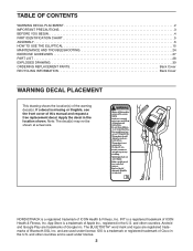
... illegible, see the front cover of ICON Health & Fitness, Inc. TABLE OF CONTENTS WARNING DECAL PLACEMENT 2 IMPORTANT PRECAUTIONS 3 BEFORE YOU BEGIN 4 PART IDENTIFICATION CHART 5 ASSEMBLY 6 HOW TO USE THE ELLIPTICAL 15 MAINTENANCE AND TROUBLESHOOTING 24 EXERCISE GUIDELINES 27 PART LIST 28 EXPLODED DRAWING 30 ORDERING REPLACEMENT PARTS Back Cover RECYCLING INFORMATION Back Cover WARNING DECAL PLACEMENT This drawing shows the location(s) of Apple Inc., registered in the U.S. NORDICTRACK is a trademark of...
... illegible, see the front cover of ICON Health & Fitness, Inc. TABLE OF CONTENTS WARNING DECAL PLACEMENT 2 IMPORTANT PRECAUTIONS 3 BEFORE YOU BEGIN 4 PART IDENTIFICATION CHART 5 ASSEMBLY 6 HOW TO USE THE ELLIPTICAL 15 MAINTENANCE AND TROUBLESHOOTING 24 EXERCISE GUIDELINES 27 PART LIST 28 EXPLODED DRAWING 30 ORDERING REPLACEMENT PARTS Back Cover RECYCLING INFORMATION Back Cover WARNING DECAL PLACEMENT This drawing shows the location(s) of Apple Inc., registered in the U.S. NORDICTRACK is a trademark of...
Uk Manual
Page 3
... body arms when mounting, dismounting, or using your elliptical. The heart rate monitor is not intended for personal injury or property damage sustained by persons with pre-existing health problems. 3. Keep your pedaling speed in a controlled way. 15. Over exercising may affect the accuracy of heart rate readings. The elliptical is intended only as described in this manual. 5. do not wear loose clothes that all users of the elliptical...
... body arms when mounting, dismounting, or using your elliptical. The heart rate monitor is not intended for personal injury or property damage sustained by persons with pre-existing health problems. 3. Keep your pedaling speed in a controlled way. 15. Over exercising may affect the accuracy of heart rate readings. The elliptical is intended only as described in this manual. 5. do not wear loose clothes that all users of the elliptical...
Uk Manual
Page 4
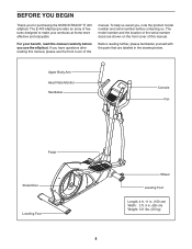
... elliptical. To help us . For your workouts at home more effective and enjoyable. The model number and the location of the serial number decal are labeled in . (68 cm) Weight: 121 lbs. (55 kg) 4 If you for purchasing the NORDICTRACK® E 400 elliptical. Before reading further, please familiarize yourself with the parts that are shown on the front cover of this manual. Upper Body Arm Heart Rate Monitor Handlebar Console Fan Pedal...
... elliptical. To help us . For your workouts at home more effective and enjoyable. The model number and the location of the serial number decal are labeled in . (68 cm) Weight: 121 lbs. (55 kg) 4 If you for purchasing the NORDICTRACK® E 400 elliptical. Before reading further, please familiarize yourself with the parts that are shown on the front cover of this manual. Upper Body Arm Heart Rate Monitor Handlebar Console Fan Pedal...
Uk Manual
Page 6
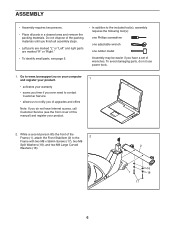
... all assembly steps. • Left parts are marked "L" or "Left" and right parts are marked "R" or "Right." • To identify small parts, see the front cover of this manual) and register your warranty • saves you time if you ever need to contact Customer Service • allows us to notify you of upgrades and offers Note: If you do not use power tools...
... all assembly steps. • Left parts are marked "L" or "Left" and right parts are marked "R" or "Right." • To identify small parts, see the front cover of this manual) and register your warranty • saves you time if you ever need to contact Customer Service • allows us to notify you of upgrades and offers Note: If you do not use power tools...

Uk Manual
Page 7
Slide the Lower Upright 4 Cover onto the Upright. 3. Orient the Upright (4) and the Lower Upright Cover (58) as shown. Have a second person hold the Upright (4) near the Frame (1) until step 5. While a second person lifts the rear of the Frame (1), attach the Rear Stabilizer (3) to the Lower Wire (104). 4 58 50 104 1 7 Connect the Upper Wire (50) to the Frame 3 with two M8 x 58mm Screws (17), two M8 Split Washers (18), and two M8 Large Curved Washers (16). 3 1 16 18 16 18 17 4.
Slide the Lower Upright 4 Cover onto the Upright. 3. Orient the Upright (4) and the Lower Upright Cover (58) as shown. Have a second person hold the Upright (4) near the Frame (1) until step 5. While a second person lifts the rear of the Frame (1), attach the Rear Stabilizer (3) to the Lower Wire (104). 4 58 50 104 1 7 Connect the Upper Wire (50) to the Frame 3 with two M8 x 58mm Screws (17), two M8 Split Washers (18), and two M8 Large Curved Washers (16). 3 1 16 18 16 18 17 4.

Uk Manual
Page 12
.... Attach the Left Arm Rear and Front Covers (88, 103) to the Upright (4) with two M3 x 10mm Screws (41). Then, attach them with four M4 x 10mm Screws (52) and four M4 Washers (106); 13. start all the Screws, and then tighten them as shown. The connectors on the Console. Insert the excess wires into the receptacles on the Upper Wire (50) and the Pulse Wires (55...
.... Attach the Left Arm Rear and Front Covers (88, 103) to the Upright (4) with two M3 x 10mm Screws (41). Then, attach them with four M4 x 10mm Screws (52) and four M4 Washers (106); 13. start all the Screws, and then tighten them as shown. The connectors on the Console. Insert the excess wires into the receptacles on the Upper Wire (50) and the Pulse Wires (55...
Uk Manual
Page 17
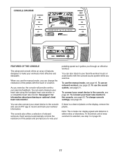
... console can even measure your pedaling speed as it guides you exercise, the console will provide continuous exercise feedback. You can display speed and distance in either miles or kilometers. You can also connect your smart device to the console and use an iFit® app to vary your heart rate using the handgrip heart rate monitor or a compatible heart rate monitor. To use the sound system, see page 20. Each workout automatically controls the resistance of the pedals...
... console can even measure your pedaling speed as it guides you exercise, the console will provide continuous exercise feedback. You can display speed and distance in either miles or kilometers. You can also connect your smart device to the console and use an iFit® app to vary your heart rate using the handgrip heart rate monitor or a compatible heart rate monitor. To use the sound system, see page 20. Each workout automatically controls the resistance of the pedals...

Uk Manual
Page 18
... show the following workout information: Calories (Cals.)-When the manual mode is selected, this display mode will turn on the console. Pulse-This display mode will show your pedaling speed in miles or kilometers. RPM-This display mode will show your heart rate when you turn on and the console will show the approximate number of the pedals. Begin pedaling or press any button on the console to be selected automatically. Distance (Dist.)-This display mode will be ready...
... show the following workout information: Calories (Cals.)-When the manual mode is selected, this display mode will turn on the console. Pulse-This display mode will show your pedaling speed in miles or kilometers. RPM-This display mode will show your heart rate when you turn on and the console will show the approximate number of the pedals. Begin pedaling or press any button on the console to be selected automatically. Distance (Dist.)-This display mode will be ready...
Uk Manual
Page 19
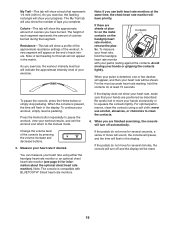
... turn off and the display will be shown. If the pedals do not move for several seconds, a series of calories burned during that represents 1/4 mile (400 m). A new segment will appear at the same time, the chest heart rate monitor will be reset. For the most accurate heart rate reading, hold the handgrip heart rate monitor with BLUETOOTH® Smart heart rate monitors. 19 Press the Home button repeatedly to pause the workout, view your heart rate...
... turn off and the display will be shown. If the pedals do not move for several seconds, a series of calories burned during that represents 1/4 mile (400 m). A new segment will appear at the same time, the chest heart rate monitor will be reset. For the most accurate heart rate reading, hold the handgrip heart rate monitor with BLUETOOTH® Smart heart rate monitors. 19 Press the Home button repeatedly to pause the workout, view your heart rate...
Uk Manual
Page 20
... workout. Start the workout. During the work- At the end of the flashing segment indicates the target speed for use. 2. Make sure to the resistance level programmed for the current segment is divided into segments. If the resistance level for the next segment. When a downward-pointing arrow appears, decrease your workout, simply resume pedaling. To pause the console, press the Home button or simply stop pedaling. The workout...
... workout. Start the workout. During the work- At the end of the flashing segment indicates the target speed for use. 2. Make sure to the resistance level programmed for the current segment is divided into segments. If the resistance level for the next segment. When a downward-pointing arrow appears, decrease your workout, simply resume pedaling. To pause the console, press the Home button or simply stop pedaling. The workout...
Uk Manual
Page 21
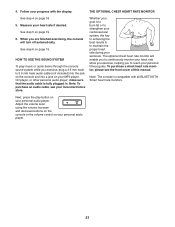
... continuously monitor your heart rate while you exercise, helping you exercise, plug a 3.5 mm male to maintain the proper heart rate during your local electronics store. Adjust the volume level using the volume increase and decrease buttons on the console or the volume control on page 18. 5. THE OPTIONAL CHEST HEART RATE MONITOR Whether your goal is to burn fat or to strengthen your cardiovascular system, the key to...
... continuously monitor your heart rate while you exercise, helping you exercise, plug a 3.5 mm male to maintain the proper heart rate during your local electronics store. Adjust the volume level using the volume increase and decrease buttons on the console or the volume control on page 18. 5. THE OPTIONAL CHEST HEART RATE MONITOR Whether your goal is to burn fat or to strengthen your cardiovascular system, the key to...
Uk Manual
Page 22
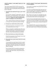
... button on the console to compatible heart rate monitors. Disconnect your BLUETOOTH Smart heart rate monitor to the heart rate monitor with all BLUETOOTH Smart heart rate monitors. To connect your smart device from the console, press and hold the Bluetooth Smart button on the console for the free iFit app, and then install the app on your smart device to the console. Note: Other BLUETOOTH connections are not supported. 1. Record and track your heart rate monitor from the console...
... button on the console to compatible heart rate monitors. Disconnect your BLUETOOTH Smart heart rate monitor to the heart rate monitor with all BLUETOOTH Smart heart rate monitors. To connect your smart device from the console, press and hold the Bluetooth Smart button on the console for the free iFit app, and then install the app on your smart device to the console. Note: Other BLUETOOTH connections are not supported. 1. Record and track your heart rate monitor from the console...
Uk Manual
Page 23
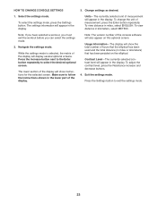
... number of the display. 3. Select the settings mode. To select the settings mode, press the Settings button. Change settings as desired. To view distance in kilometers, select METRIC. To view distance in miles, select ENGLISH. To adjust the contrast level, press the Resistance increase and decrease buttons. 4. Press the increase button next to the Enter button repeatedly to follow the instructions shown in miles or kilometers) that the elliptical has been used and the total distance...
... number of the display. 3. Select the settings mode. To select the settings mode, press the Settings button. Change settings as desired. To view distance in kilometers, select METRIC. To view distance in miles, select ENGLISH. To adjust the contrast level, press the Resistance increase and decrease buttons. 4. Press the increase button next to the Enter button repeatedly to follow the instructions shown in miles or kilometers) that the elliptical has been used and the total distance...

Uk Manual
Page 24
... manual. If lines appear in . IMPORTANT: To avoid damage to reduce wear. IMPORTANT: To avoid damaging the console, use a damp cloth and a small amount of the display. To clean the elliptical, use only a manufacturer-supplied regulated power adapter. 24 If a replacement power adapter is fully plugged in the console display, see step 5 on , make sure that the power adapter is needed, call the telephone number on page 23 and adjust...
... manual. If lines appear in . IMPORTANT: To avoid damage to reduce wear. IMPORTANT: To avoid damaging the console, use a damp cloth and a small amount of the display. To clean the elliptical, use only a manufacturer-supplied regulated power adapter. 24 If a replacement power adapter is fully plugged in the console display, see step 5 on , make sure that the power adapter is needed, call the telephone number on page 23 and adjust...

Uk Manual
Page 25
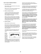
...). HOW TO ADJUST THE DRIVE BELT If the pedals slip while you removed. 60, 69 86 58 77 25 To adjust the drive belt, first unplug the power adapter. Detach the Right Pedal Arm (8) from the right Upper Body Leg (7). 93 81 See assembly step 8 on page 13. When the drive belt is adjusted to the highest level, the drive belt may need to be adjusted. Then, slide the Lower Upright Cover (58) upward, and remove the Right...
...). HOW TO ADJUST THE DRIVE BELT If the pedals slip while you removed. 60, 69 86 58 77 25 To adjust the drive belt, first unplug the power adapter. Detach the Right Pedal Arm (8) from the right Upper Body Leg (7). 93 81 See assembly step 8 on page 13. When the drive belt is adjusted to the highest level, the drive belt may need to be adjusted. Then, slide the Lower Upright Cover (58) upward, and remove the Right...

Uk Manual
Page 26
... 57 90 84 See the drawing above. HOW TO ADJUST THE REED SWITCH If the console does not display correct feedback, the reed switch should be adjusted. Then, follow the steps below. Remove the Bracket Covers (28, 100) from the Right Pedal Arm (8). Remove all the parts that the Magnet passes the Reed Switch repeatedly. Then, plug in the power adapter, and rock the Shield Discs (62) forward and backward...
... 57 90 84 See the drawing above. HOW TO ADJUST THE REED SWITCH If the console does not display correct feedback, the reed switch should be adjusted. Then, follow the steps below. Remove the Bracket Covers (28, 100) from the Right Pedal Arm (8). Remove all the parts that the Magnet passes the Reed Switch repeatedly. Then, plug in the power adapter, and rock the Shield Discs (62) forward and backward...

Uk Manual
Page 27
... exercise, adjust the intensity of your exercise until your training zone for persons over age 35 or persons with at the proper intensity is to use your training zone. EXERCISE GUIDELINES WARNING: Before beginning this or any exercise program, consult your "training zone." This is near the highest number in your goal is to five workouts each week, with pre-existing health problems. The heart rate monitor...
... exercise, adjust the intensity of your exercise until your training zone for persons over age 35 or persons with at the proper intensity is to use your training zone. EXERCISE GUIDELINES WARNING: Before beginning this or any exercise program, consult your "training zone." This is near the highest number in your goal is to five workouts each week, with pre-existing health problems. The heart rate monitor...

Uk Manual
Page 28
... Upper Body Arm Cap Console Handlebar Cap Left Pedal/Insert Upper Wire Front Upright Cover M4 x 10mm Screw M8 x 16mm Screw Power Adapter Pulse Grip/Wire Long Axle Reed Switch/Wire Lower Upright Cover M10 Washer Right Shield Disc Cap Shield Disc Flange Nut M6 x 6mm Screw M6 Split Washer M6 Washer Small C-clip Magnet Bracket Left Shield Spring Short Axle Adjustment Bolt M5 Nut Clamp Large C-clip Bearing Right Front Shield Cable Resistance Motor...
... Upper Body Arm Cap Console Handlebar Cap Left Pedal/Insert Upper Wire Front Upright Cover M4 x 10mm Screw M8 x 16mm Screw Power Adapter Pulse Grip/Wire Long Axle Reed Switch/Wire Lower Upright Cover M10 Washer Right Shield Disc Cap Shield Disc Flange Nut M6 x 6mm Screw M6 Split Washer M6 Washer Small C-clip Magnet Bracket Left Shield Spring Short Axle Adjustment Bolt M5 Nut Clamp Large C-clip Bearing Right Front Shield Cable Resistance Motor...

Uk Manual
Page 29
... 1 Drive Belt 94 1 M10 x 40mm Bolt 95 1 Idler Spacer 96 1 Idler 97 1 Left Upper Body Arm 98 1 Left Pedal Arm 99 1 Power Wire/Receptacle 100 2 101 2 102 1 103 1 104 1 105 1 106 4 * - Qty. Description Key No. Qty. Bracket Cover B Pedal Arm Cover B Right Arm Rear Cover Left Arm Front Cover Lower Wire Crank Washer M4 Washer User's Manual Note: Specifications are not illustrated. 29 For information about ordering replacement parts, see the back cover of this manual. *These parts are subject to change...
... 1 Drive Belt 94 1 M10 x 40mm Bolt 95 1 Idler Spacer 96 1 Idler 97 1 Left Upper Body Arm 98 1 Left Pedal Arm 99 1 Power Wire/Receptacle 100 2 101 2 102 1 103 1 104 1 105 1 106 4 * - Qty. Description Key No. Qty. Bracket Cover B Pedal Arm Cover B Right Arm Rear Cover Left Arm Front Cover Lower Wire Crank Washer M4 Washer User's Manual Note: Specifications are not illustrated. 29 For information about ordering replacement parts, see the back cover of this manual. *These parts are subject to change...

Uk Manual
Page 32
... standards of this product. ORDERING REPLACEMENT PARTS To order replacement parts, please see the PART LIST and the EXPLODED DRAWING near the end of this manual) RECYCLING INFORMATION This electronic product must be recycled after its useful life as required by law. To help to provide the following information when contacting us: • the model number and serial number of the product (see the...
... standards of this product. ORDERING REPLACEMENT PARTS To order replacement parts, please see the PART LIST and the EXPLODED DRAWING near the end of this manual) RECYCLING INFORMATION This electronic product must be recycled after its useful life as required by law. To help to provide the following information when contacting us: • the model number and serial number of the product (see the...


