PS110 Reference Manual
Page 7
Using Advanced Functions 5-20 Servicing Multiple NetWare Bindery File Servers 5-20 Attaching to More Than One NetWare Print Server 5-21 Using Logical Ports 5-22 Configuring Logical Printers on the Print Server 5-22 Configuring NetWare File Server to Connect to Logical Printers 5-23 Chapter 6 UNIX Printing Using TCP/IP ... Print Server Administration Program 7-1 Advanced Print Server Configuration 7-4 System Menu Tab 7-5 NetWare PServer Menu Tab 7-6 NetWare RPrinter Menu Tab 7-9 TCP/IP Menu Tab 7-10 Logical Port Menu Tab 7-12 Contents vii
Using Advanced Functions 5-20 Servicing Multiple NetWare Bindery File Servers 5-20 Attaching to More Than One NetWare Print Server 5-21 Using Logical Ports 5-22 Configuring Logical Printers on the Print Server 5-22 Configuring NetWare File Server to Connect to Logical Printers 5-23 Chapter 6 UNIX Printing Using TCP/IP ... Print Server Administration Program 7-1 Advanced Print Server Configuration 7-4 System Menu Tab 7-5 NetWare PServer Menu Tab 7-6 NetWare RPrinter Menu Tab 7-9 TCP/IP Menu Tab 7-10 Logical Port Menu Tab 7-12 Contents vii
PS110 Reference Manual
Page 11
...Setup Complete Window 3-7 Figure 3-7. Figures Figure 1-1. Front Panel of the Model PS104 Print Server 1-2 Front Panel of the Model PS105 Print Server 1-2 Front Panel of the ... 3-6 Figure 3-6. Add Printer Wizard Window (Driver Installation 3-13 Figure 3-16. NETGEAR Print Server Software Installation Window 3-4 Figure 3-4. Choose Destination Location Window 3-5 Figure 3-5. Epson Spool Manager Queue... Setup Window 3-11 Figure 3-13. Add Port Window (Setup Complete 3-16 Figure 3-19. Setup Icon 3-9 Figure 3-9. Figure 1-5. Setup...
...Setup Complete Window 3-7 Figure 3-7. Figures Figure 1-1. Front Panel of the Model PS104 Print Server 1-2 Front Panel of the Model PS105 Print Server 1-2 Front Panel of the ... 3-6 Figure 3-6. Add Printer Wizard Window (Driver Installation 3-13 Figure 3-16. NETGEAR Print Server Software Installation Window 3-4 Figure 3-4. Choose Destination Location Window 3-5 Figure 3-5. Epson Spool Manager Queue... Setup Window 3-11 Figure 3-13. Add Port Window (Setup Complete 3-16 Figure 3-19. Setup Icon 3-9 Figure 3-9. Figure 1-5. Setup...
PS110 Reference Manual
Page 12
...(Manufacturer and Model of Printer) .........4-13 Figure 4-16. Add Printer Wizard Window (Print Test Page 4-16 Figure 4-19. NETGEAR Print Server Software Installation Window 4-20 Figure 4-23. Setup Complete Window 4-23 Figure 4-26. Choose Destination Location Window 4-5 ...Wizard Window (Sharing Ports Screen 4-15 Figure 4-18. Admin Installation Option Window 4-19 Figure 4-22. Select Program Folder Window 4-22 Figure 4-25. NETGEAR Print Server Software Installation Window 4-4 Figure 4-4. Add Port Window (Added port successfully 4-12 Figure 4-14. NETGEAR Print Server Administration...
...(Manufacturer and Model of Printer) .........4-13 Figure 4-16. Add Printer Wizard Window (Print Test Page 4-16 Figure 4-19. NETGEAR Print Server Software Installation Window 4-20 Figure 4-23. Setup Complete Window 4-23 Figure 4-26. Choose Destination Location Window 4-5 ...Wizard Window (Sharing Ports Screen 4-15 Figure 4-18. Admin Installation Option Window 4-19 Figure 4-22. Select Program Folder Window 4-22 Figure 4-25. NETGEAR Print Server Software Installation Window 4-4 Figure 4-4. Add Port Window (Added port successfully 4-12 Figure 4-14. NETGEAR Print Server Administration...
PS110 Reference Manual
Page 13
... Window 7-5 NetWare PServer Tab Window 7-7 NetWare RPrinter Tab Window 7-9 TCP/IP Menu Tab Window 7-10 Logical Port Menu Tab Window 7-12 Figure B-1. Figure D-3. TCP/IP Menu 4-28 Figure 7-1. Figure 7-4. Figure 7-5. Three Main Address Classes B-2 Figure B-2. NETGEAR Print Server Administration Program Window 4-27 Figure 4-30. Figure 4-28. Create NDPS Manager Object Window D-2 Create...
... Window 7-5 NetWare PServer Tab Window 7-7 NetWare RPrinter Tab Window 7-9 TCP/IP Menu Tab Window 7-10 Logical Port Menu Tab Window 7-12 Figure B-1. Figure D-3. TCP/IP Menu 4-28 Figure 7-1. Figure 7-4. Figure 7-5. Three Main Address Classes B-2 Figure B-2. NETGEAR Print Server Administration Program Window 4-27 Figure 4-30. Figure 4-28. Create NDPS Manager Object Window D-2 Create...

PS110 Reference Manual
Page 15
... on All Menu Tabs 7-4 System Menu Tab Fields 7-6 NetWare PSERVER Menu Tab Fields 7-7 NetWare RPrinter Menu Tab Fields 7-9 TCP/IP Menu Tab Fields 7-11 Logical Port Menu Tab Fields 7-13 Advanced Print Server Configuration Menu Bar Selections 7-14 Printer Menu Options 7-14 PSCONFIG Program Options 7-15 Tables xv Fields and Descriptions...
... on All Menu Tabs 7-4 System Menu Tab Fields 7-6 NetWare PSERVER Menu Tab Fields 7-7 NetWare RPrinter Menu Tab Fields 7-9 TCP/IP Menu Tab Fields 7-11 Logical Port Menu Tab Fields 7-13 Advanced Print Server Configuration Menu Bar Selections 7-14 Printer Menu Options 7-14 PSCONFIG Program Options 7-15 Tables xv Fields and Descriptions...
PS110 Reference Manual
Page 21
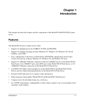
...multiple operating systems (Windows 95, Windows 98, Windows NT, Novell NetWare, and UNIX) • Easy configuration of the device with FirstGear, NETGEAR configuration software that assures fast and easy setup for Windows 95, Windows 98, and Window NT users • Support for 10BASE-T Ethernet connection ...with four 10BASE-T ports on the Model PS104 Print Server, four 10BASE-T ports and a BNC port on the Model PS105 Print Server, or 10/ 100BASE-T Ethernet connection on the Model PS110 Print Server •...
...multiple operating systems (Windows 95, Windows 98, Windows NT, Novell NetWare, and UNIX) • Easy configuration of the device with FirstGear, NETGEAR configuration software that assures fast and easy setup for Windows 95, Windows 98, and Window NT users • Support for 10BASE-T Ethernet connection ...with four 10BASE-T ports on the Model PS104 Print Server, four 10BASE-T ports and a BNC port on the Model PS105 Print Server, or 10/ 100BASE-T Ethernet connection on the Model PS110 Print Server •...
PS110 Reference Manual
Page 22
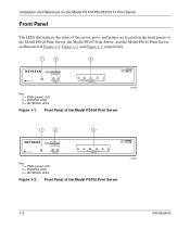
...Introduction Blinking=Rx Col NETWORK MODEL PS104 8625EA Key: 1 = PWR (power) LED 2 = PRINTER LEDs 3 = NETWORK LEDs Figure 1-1. Installation and Reference for the Model PS104/PS105/PS110 Print Server Front Panel The LEDs that indicate the status of the server, ports, and printer are located on the... front panels of the Model PS104 Print Server, the Model PS105 Print Server, and the Model ...
...Introduction Blinking=Rx Col NETWORK MODEL PS104 8625EA Key: 1 = PWR (power) LED 2 = PRINTER LEDs 3 = NETWORK LEDs Figure 1-1. Installation and Reference for the Model PS104/PS105/PS110 Print Server Front Panel The LEDs that indicate the status of the server, ports, and printer are located on the... front panels of the Model PS104 Print Server, the Model PS105 Print Server, and the Model ...
PS110 Reference Manual
Page 23
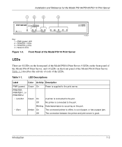
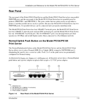
... The connection between the printer and print server is occurring on the front panel of the Model PS105 Print Server, and 10 LEDs on the port. Table 1-1 describes the activity of each of paper, or has a paper jam. Off No printer is connected to the print server. Installation and Reference... for the Model PS104/PS105/PS110 Print Server 1 2 3 4 10/100 Mbps Print Server MODEL PS110 PWR Link/Act Alert PRINTER 1 Link/Act Alert PRINTER 2 Link 100M Rx Tx...
... The connection between the printer and print server is occurring on the front panel of the Model PS105 Print Server, and 10 LEDs on the port. Table 1-1 describes the activity of each of paper, or has a paper jam. Off No printer is connected to the print server. Installation and Reference... for the Model PS104/PS105/PS110 Print Server 1 2 3 4 10/100 Mbps Print Server MODEL PS110 PWR Link/Act Alert PRINTER 1 Link/Act Alert PRINTER 2 Link 100M Rx Tx...
PS110 Reference Manual
Page 24
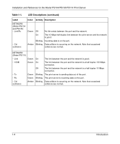
...is receiving data on the port. • Col (collision) Amber Blinking Data collision is occurring on the network. Installation and Reference for the Model PS104/PS105/PS110 Print Server Table 1-1. On The 10 Mbps half-duplex link between the port and the network. LED Descriptions... (continued) Label Color Activity Description NETWORK (Model PS104 and PS105) • Link/Rx Green Off...
...is receiving data on the port. • Col (collision) Amber Blinking Data collision is occurring on the network. Installation and Reference for the Model PS104/PS105/PS110 Print Server Table 1-1. On The 10 Mbps half-duplex link between the port and the network. LED Descriptions... (continued) Label Color Activity Description NETWORK (Model PS104 and PS105) • Link/Rx Green Off...
PS110 Reference Manual
Page 25
... and the Model PS105 Print Server allows you to select Normal (MDI-X) or Uplink (MDI) wiring for NETWORK port 1, eliminating the need to use a crossover cable. Normal/Uplink Push Button on the Model PS104/PS105 Print Server The Normal/Uplink push button on the first two print servers accept either a printer or...
... and the Model PS105 Print Server allows you to select Normal (MDI-X) or Uplink (MDI) wiring for NETWORK port 1, eliminating the need to use a crossover cable. Normal/Uplink Push Button on the Model PS104/PS105 Print Server The Normal/Uplink push button on the first two print servers accept either a printer or...
PS110 Reference Manual
Page 26
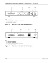
... Server 9225EA 1 PRINTER 2 2 PRINTER 1 3 4 NETWORK 12VDC 1.2A Key: 1 = PRINTER 2 (parallel) port 2 = PRINTER 1 (parallel) port 3 = NETWORK port (10/100BASE-T connector) 4 = Power adapter receptacle Figure 1-6. Installation and Reference for the Model PS104/PS105/PS110 Print Server 1 2 3 4 PRINTER NETWORK 4 3 2 1 BNC 12VDC 1.2A Normal/Uplink Key: 1 = PRINTER Port 2 = Network Port (Four 10BASE-T and One BNC Connector) 3 = Normal/Uplink push button...
... Server 9225EA 1 PRINTER 2 2 PRINTER 1 3 4 NETWORK 12VDC 1.2A Key: 1 = PRINTER 2 (parallel) port 2 = PRINTER 1 (parallel) port 3 = NETWORK port (10/100BASE-T connector) 4 = Power adapter receptacle Figure 1-6. Installation and Reference for the Model PS104/PS105/PS110 Print Server 1 2 3 4 PRINTER NETWORK 4 3 2 1 BNC 12VDC 1.2A Normal/Uplink Key: 1 = PRINTER Port 2 = Network Port (Four 10BASE-T and One BNC Connector) 3 = Normal/Uplink push button...
PS110 Reference Manual
Page 28
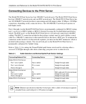
...10BASE 2 connection to other devices. Cable Selection and Normal/Uplink Push Button Settings Connecting Network Port Model PS104 Print Server Port 1 set to Uplink Port 1 set to Normal Ports 2 through 4 Model PS105 Print Server Port 1 Port 2 set to other network devices that is for Uplink wiring. The Model PS110 Print Server... for the Model PS104/PS105/PS110 Print Server Connecting Devices to 100 meters in the network segment, you must be set to Uplink Ports 3 through 5 Model PS110 Print Server Connecting Device Hub or switch PC or router PC PC Hub or switch PC Hub or switch PC ...
...10BASE 2 connection to other devices. Cable Selection and Normal/Uplink Push Button Settings Connecting Network Port Model PS104 Print Server Port 1 set to Uplink Port 1 set to Normal Ports 2 through 4 Model PS105 Print Server Port 1 Port 2 set to other network devices that is for Uplink wiring. The Model PS110 Print Server... for the Model PS104/PS105/PS110 Print Server Connecting Devices to 100 meters in the network segment, you must be set to Uplink Ports 3 through 5 Model PS110 Print Server Connecting Device Hub or switch PC or router PC PC Hub or switch PC Hub or switch PC ...
PS110 Reference Manual
Page 29
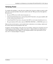
...• On the Model PS110 Print Server, the green Link LED on each connected printer port is on. • The green Link/Act LED on the connected PRINTER, PRINTER 1, or PRINTER 2 port is on. If required, verify the integrity of the representative in working condition and the ... print server by resetting it. If the problem continues and you have completed all the preceding diagnoses, contact NETGEAR Customer Support. Installation and Reference for the Model PS104/PS105/PS110 Print Server Verifying Power To complete the installation, connect the power adapter first to the power adapter...
...• On the Model PS110 Print Server, the green Link LED on each connected printer port is on. • The green Link/Act LED on the connected PRINTER, PRINTER 1, or PRINTER 2 port is on. If required, verify the integrity of the representative in working condition and the ... print server by resetting it. If the problem continues and you have completed all the preceding diagnoses, contact NETGEAR Customer Support. Installation and Reference for the Model PS104/PS105/PS110 Print Server Verifying Power To complete the installation, connect the power adapter first to the power adapter...

PS110 Reference Manual
Page 38
... each PC: 1. To set up each PC that you named in step 7 in Figure 3-7, that will print to the print server. Firstgear for the Model PS104/PS105/PS110 Print Server Setting Up Your PC to the printer port. • The AC adapter is plugged into the LAN.
... each PC: 1. To set up each PC that you named in step 7 in Figure 3-7, that will print to the print server. Firstgear for the Model PS104/PS105/PS110 Print Server Setting Up Your PC to the printer port. • The AC adapter is plugged into the LAN.

PS110 Reference Manual
Page 40
... as illustrated in the background while you work through subsequent setup windows because you will use this window to browse again for the Model PS104/PS105/PS110 Print Server 5. Click on the Refresh button, which will appear empty when the Printer Select window opens. The Printer Select .... Figure 3-10. If so, check the cable connections and click on OK. Installation and Reference for a port. 3-10 Microsoft Windows 95 and Windows 98 Printing Printer Select Window (Add Port) Note: If the cables are not properly connected, your PC screen will initiate the PC to complete the ...
... as illustrated in the background while you work through subsequent setup windows because you will use this window to browse again for the Model PS104/PS105/PS110 Print Server 5. Click on the Refresh button, which will appear empty when the Printer Select window opens. The Printer Select .... Figure 3-10. If so, check the cable connections and click on OK. Installation and Reference for a port. 3-10 Microsoft Windows 95 and Windows 98 Printing Printer Select Window (Add Port) Note: If the cables are not properly connected, your PC screen will initiate the PC to complete the ...

PS110 Reference Manual
Page 41
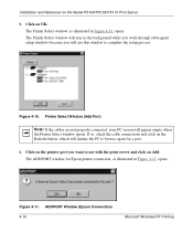
... print connection, as illustrated in Figure 3-11, opens. Figure 3-11. Click on Yes if you do have an Epson Stylus Color printer attached to the port, and continue to use with the print server, and click on your hard drive. The ADDPORT window for the Model...
... print connection, as illustrated in Figure 3-11, opens. Figure 3-11. Click on Yes if you do have an Epson Stylus Color printer attached to the port, and continue to use with the print server, and click on your hard drive. The ADDPORT window for the Model...
PS110 Reference Manual
Page 42
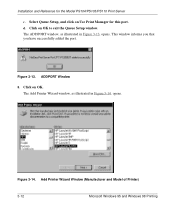
The ADDPORT window, as illustrated in Figure 3-13, opens. This window informs you that you have successfully added the port. Select Queue Setup, and click on Use Print Manager for the Model PS104/PS105/PS110 Print Server c. d. Click on OK to exit the Queue Setup window. Add Printer Wizard Window (Manufacturer and Model of Printer) 3-12 Microsoft Windows 95 and Windows 98 Printing The Add Printer Wizard window, as illustrated in Figure 3-14, opens. Installation and Reference for this port. Figure 3-13. ADDPORT Window 8. Click on OK. Figure 3-14.
The ADDPORT window, as illustrated in Figure 3-13, opens. This window informs you that you have successfully added the port. Select Queue Setup, and click on Use Print Manager for the Model PS104/PS105/PS110 Print Server c. d. Click on OK to exit the Queue Setup window. Add Printer Wizard Window (Manufacturer and Model of Printer) 3-12 Microsoft Windows 95 and Windows 98 Printing The Add Printer Wizard window, as illustrated in Figure 3-14, opens. Installation and Reference for this port. Figure 3-13. ADDPORT Window 8. Click on OK. Figure 3-14.

PS110 Reference Manual
Page 46
Click on Finish. You are now ready to use the printer attached to complete the setup process. Select Yes when asked to print a test page, and click on End to your print server. 3-16 Microsoft Windows 95 and Windows 98 Printing The Add Printer window closes and the Printer Select window, as illustrated in Figure 3-18, comes back into view. Add Port Window (Setup Complete) 13. Figure 3-18. Installation and Reference for the Model PS104/PS105/PS110 Print Server 12.
Click on Finish. You are now ready to use the printer attached to complete the setup process. Select Yes when asked to print a test page, and click on End to your print server. 3-16 Microsoft Windows 95 and Windows 98 Printing The Add Printer window closes and the Printer Select window, as illustrated in Figure 3-18, comes back into view. Add Port Window (Setup Complete) 13. Figure 3-18. Installation and Reference for the Model PS104/PS105/PS110 Print Server 12.

PS110 Reference Manual
Page 66
To set up each PC that will print to the printer port. • The AC adapter is plugged into the LAN. Figure 4-7. Firstgear for the Model PS104/PS105/PS110 Print Server Setting Up Your PC to Recognize the Print Server You must set up each PC: 1. Before proceeding, verify that you named ...
To set up each PC that will print to the printer port. • The AC adapter is plugged into the LAN. Figure 4-7. Firstgear for the Model PS104/PS105/PS110 Print Server Setting Up Your PC to Recognize the Print Server You must set up each PC: 1. Before proceeding, verify that you named ...
PS110 Reference Manual
Page 68
... to complete the setup process. Printer Select Window (Add Port) Note: If the cables are not properly connected, your PC screen will stay in the background while you work through subsequent setup windows because you want to browse again for the Model PS104/PS105/PS110 Print Server 5. The ADDPORT window for Epson...
... to complete the setup process. Printer Select Window (Add Port) Note: If the cables are not properly connected, your PC screen will stay in the background while you work through subsequent setup windows because you want to browse again for the Model PS104/PS105/PS110 Print Server 5. The ADDPORT window for Epson...


