GSM7212 Hardware manual
Page 7
Chapter 1 About This Manual The Managed Layer 2 Switches GSM7212, GSM7224, and GSM7248 Hardware Installation Guide contains information for network managers familiar with network management concepts and terminology This guide uses the ...Ignoring this type of importance or special interest. Audience, Conventions, Formats, and Scope This guide is intended for hardware installation of the NETGEAR® GSM7212, GSM7224, and GSM7248 switches. Typographical Conventions Italics Bold Fixed Emphasis, books, CDs, URL names User input Screen text, file and server names, extensions, commands...
Chapter 1 About This Manual The Managed Layer 2 Switches GSM7212, GSM7224, and GSM7248 Hardware Installation Guide contains information for network managers familiar with network management concepts and terminology This guide uses the ...Ignoring this type of importance or special interest. Audience, Conventions, Formats, and Scope This guide is intended for hardware installation of the NETGEAR® GSM7212, GSM7224, and GSM7248 switches. Typographical Conventions Italics Bold Fixed Emphasis, books, CDs, URL names User input Screen text, file and server names, extensions, commands...
GSM7212 Hardware manual
Page 8
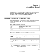
... Manual publication date • ProSafe 12-Port Gigabit L2 Managed Switch Model GSM7212 • ProSafe 24-Port Gigabit L2 Managed Switch Model GSM7224 • ProSafe 48-Port Gigabit L2 Managed Switch Model GSM7248 March 2006 Note: Product updates are available on the NETGEAR, Inc. Web site at http://kbserver.netgear.com. 1-2 About This Manual v1.0, March 2006 This manual is...
... Manual publication date • ProSafe 12-Port Gigabit L2 Managed Switch Model GSM7212 • ProSafe 24-Port Gigabit L2 Managed Switch Model GSM7224 • ProSafe 48-Port Gigabit L2 Managed Switch Model GSM7248 March 2006 Note: Product updates are available on the NETGEAR, Inc. Web site at http://kbserver.netgear.com. 1-2 About This Manual v1.0, March 2006 This manual is...

GSM7212 Hardware manual
Page 9
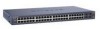
... Switch Model GSM7224 • ProSafe 48-Port Gigabit L2 Managed Switch Model GSM7248 These switches can use to eliminate bottlenecks, boost performance, and increase productivity. It contains LEDs, RJ-45 jacks, SFP module bays, and a console port. LEDs Figure 2-1 Introduction RJ-45 jacks v1.0, March 2006 SFP Console module port bays 2-1 Chapter 2 Introduction The NETGEAR Managed Layer 2 Switch...
... Switch Model GSM7224 • ProSafe 48-Port Gigabit L2 Managed Switch Model GSM7248 These switches can use to eliminate bottlenecks, boost performance, and increase productivity. It contains LEDs, RJ-45 jacks, SFP module bays, and a console port. LEDs Figure 2-1 Introduction RJ-45 jacks v1.0, March 2006 SFP Console module port bays 2-1 Chapter 2 Introduction The NETGEAR Managed Layer 2 Switch...
GSM7212 Hardware manual
Page 10
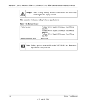
...Layer 2 Switches GSM7212, GSM7224, and GSM7248 Hardware ...Installation Guide The following table describes the LEDs on the port.. • Solid green: Link is up. • Blinking green: The port is sending or receiving packets in 10 Mbps. ACT (activity) • Blinking green: The port is detected. LED Descriptions for the supplied power cord. Power receptacle Figure 2-2 2-2 v1...(port number) SFP Port (1,000 Mbps only) • Green: Power is supplied, and the switch is operating normally. • Yellow: Power supply present, but it has failed. • Off...
...Layer 2 Switches GSM7212, GSM7224, and GSM7248 Hardware ...Installation Guide The following table describes the LEDs on the port.. • Solid green: Link is up. • Blinking green: The port is sending or receiving packets in 10 Mbps. ACT (activity) • Blinking green: The port is detected. LED Descriptions for the supplied power cord. Power receptacle Figure 2-2 2-2 v1...(port number) SFP Port (1,000 Mbps only) • Green: Power is supplied, and the switch is operating normally. • Yellow: Power supply present, but it has failed. • Off...
GSM7212 Hardware manual
Page 11
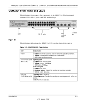
... Figure 2-3 The following figure shows the front panel of the switch. Managed Layer 2 Switches GSM7212, GSM7224, and GSM7248 Hardware Installation Guide GSM7224 Front Panel and LEDs The following table shows the GSM7224 LEDs on the front of the GSM7224. Introduction 2-3 v1.0, March 2006 Link/ACT (left) • Green: Link...-45 jacks, and SFP module bays. Table 2-2. GSM7224 LED Description LED Description Power • Green: Power is supplied, and the switch is operating normally. • Yellow: Power supply present, but it has failed. • Off: Power is detected.
... Figure 2-3 The following figure shows the front panel of the switch. Managed Layer 2 Switches GSM7212, GSM7224, and GSM7248 Hardware Installation Guide GSM7224 Front Panel and LEDs The following table shows the GSM7224 LEDs on the front of the GSM7224. Introduction 2-3 v1.0, March 2006 Link/ACT (left) • Green: Link...-45 jacks, and SFP module bays. Table 2-2. GSM7224 LED Description LED Description Power • Green: Power is supplied, and the switch is operating normally. • Yellow: Power supply present, but it has failed. • Off: Power is detected.
GSM7212 Hardware manual
Page 12
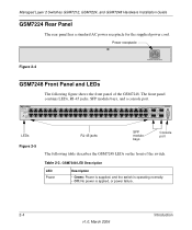
... port The following figure shows the front panel of the switch. Table 2-3. GSM7248 LED Description LED Power Description • Green: Power is supplied, and the switch is operating normally. • Off: No power is applied, or power failure. 2-4 Introduction v1.0, March 2006 Power receptacle Figure 2-4 GSM7248 Front Panel and LEDs The following table describes the...
... port The following figure shows the front panel of the switch. Table 2-3. GSM7248 LED Description LED Power Description • Green: Power is supplied, and the switch is operating normally. • Off: No power is applied, or power failure. 2-4 Introduction v1.0, March 2006 Power receptacle Figure 2-4 GSM7248 Front Panel and LEDs The following table describes the...

GSM7212 Hardware manual
Page 13
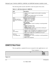
.... Power Figure 2-6 Safety Instructions Use the following precautions. • Observe and follow service markings. - GSM7248 Rear Panel The rear panel has a standard AC power receptacle for the supplied power cord. Do not ...service any product except as explained in 10 Mbps. Introduction 2-5 v1.0, March 2006 Link or Activity (right) • Green: Link is up. • Blinking green: The...guidelines to ensure your system documentation. - Managed Layer 2 Switches GSM7212, GSM7224, and GSM7248 Hardware Installation Guide Table 2-3.
.... Power Figure 2-6 Safety Instructions Use the following precautions. • Observe and follow service markings. - GSM7248 Rear Panel The rear panel has a standard AC power receptacle for the supplied power cord. Do not ...service any product except as explained in 10 Mbps. Introduction 2-5 v1.0, March 2006 Link or Activity (right) • Green: Link is up. • Blinking green: The...guidelines to ensure your system documentation. - Managed Layer 2 Switches GSM7212, GSM7224, and GSM7248 Hardware Installation Guide Table 2-3.

GSM7212 Hardware manual
Page 14
... or contact your system away from the type of external power source indicated on the power supply is damaged. - Managed Layer 2 Switches GSM7212, GSM7224, and GSM7248 Hardware Installation Guide • If any objects into the product. - If the system gets wet, see the appropriate section in your... of the type of power source required, consult your service provider or local power company. • To help avoid damaging your location. 2-6 Introduction v1.0, March 2006 Also, do not block cooling vents. • Do not spill food or liquids on your location: - 115 volts (V), 60 hertz...
... or contact your system away from the type of external power source indicated on the power supply is damaged. - Managed Layer 2 Switches GSM7212, GSM7224, and GSM7248 Hardware Installation Guide • If any objects into the product. - If the system gets wet, see the appropriate section in your... of the type of power source required, consult your service provider or local power company. • To help avoid damaging your location. 2-6 Introduction v1.0, March 2006 Also, do not block cooling vents. • Do not spill food or liquids on your location: - 115 volts (V), 60 hertz...
GSM7212 Hardware manual
Page 15
...current marked on any AC powered option intended for site modifications. • Always follow your system from a cable. Introduction 2-7 v1.0, March 2006 route cables so that the total ampere rating of the cable should be greater than the ratings marked on or ... properly grounded electrical outlets. • The peripheral power cables are firmly connected to help ensure proper grounding. Managed Layer 2 Switches GSM7212, GSM7224, and GSM7248 Hardware Installation Guide • Use only approved power cables. The power cable must use an extension cable, use in electrical ...
...current marked on any AC powered option intended for site modifications. • Always follow your system from a cable. Introduction 2-7 v1.0, March 2006 route cables so that the total ampere rating of the cable should be greater than the ratings marked on or ... properly grounded electrical outlets. • The peripheral power cables are firmly connected to help ensure proper grounding. Managed Layer 2 Switches GSM7212, GSM7224, and GSM7248 Hardware Installation Guide • Use only approved power cables. The power cable must use an extension cable, use in electrical ...

GSM7212 Hardware manual
Page 16
Managed Layer 2 Switches GSM7212, GSM7224, and GSM7248 Hardware Installation Guide 2-8 Introduction v1.0, March 2006
Managed Layer 2 Switches GSM7212, GSM7224, and GSM7248 Hardware Installation Guide 2-8 Introduction v1.0, March 2006

GSM7212 Hardware manual
Page 17
... Guide If you ordered SFP modules with 9-pin connectors • NETGEAR CD: The CD contains - Documentation including the Command Line Interface Reference for the ProSafe 7200 Series Layer-2 Switches, the Administration Manual for tabletop installation • Rack-mounting kit ... Installation 3-1 v1.0, March 2006 Configuration software - Chapter 3 Hardware Installation This chapter explains how to install the hardware for the Managed Layer 3 Fast Ethernet Switch models GSM7212, GSM7224, and GSM7248. Package Contents Each switch is missing or damaged, contact your switch, they are...
... Guide If you ordered SFP modules with 9-pin connectors • NETGEAR CD: The CD contains - Documentation including the Command Line Interface Reference for the ProSafe 7200 Series Layer-2 Switches, the Administration Manual for tabletop installation • Rack-mounting kit ... Installation 3-1 v1.0, March 2006 Configuration software - Chapter 3 Hardware Installation This chapter explains how to install the hardware for the Managed Layer 3 Fast Ethernet Switch models GSM7212, GSM7224, and GSM7248. Package Contents Each switch is missing or damaged, contact your switch, they are...

GSM7212 Hardware manual
Page 18
When unpacking a static-sensitive component from its shipping carton, leave it on the switch. Handle all straps securing the container. 2. Place the container on page 3-3. 3. Unpacking the Hardware Check the contents of the ... the boxes to make sure that all packing material. 3-2 Hardware Installation v1.0, March 2006 If possible, use antistatic floor pads, workbench pads, and an antistatic grounding strap. Managed Layer 2 Switches GSM7212, GSM7224, and GSM7248 Hardware Installation Guide Protecting Against Electrostatic Discharge Warning: Static electricity can harm ...
When unpacking a static-sensitive component from its shipping carton, leave it on the switch. Handle all straps securing the container. 2. Place the container on page 3-3. 3. Unpacking the Hardware Check the contents of the ... the boxes to make sure that all packing material. 3-2 Hardware Installation v1.0, March 2006 If possible, use antistatic floor pads, workbench pads, and an antistatic grounding strap. Managed Layer 2 Switches GSM7212, GSM7224, and GSM7248 Hardware Installation Guide Protecting Against Electrostatic Discharge Warning: Static electricity can harm ...
GSM7212 Hardware manual
Page 19
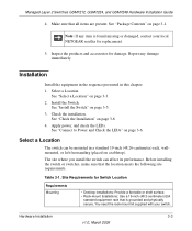
...LEDs. The site where you install the switch can be mounted in this chapter: 1. Before installing the switch or switches, make sure that all items are present. You need the rack-mount kit supplied with your local NETGEAR reseller for replacement. 5. Select a Location... contact your switch. See "Check the Installation" on page 3-6. Table 3-1. Site Requirements for damage. See "Install the Switch" on page 3-1. Hardware Installation 3-3 v1.0, March 2006 Report any item is grounded and physically secure. Install the Switch. Select a Location The switch can affect its...
...LEDs. The site where you install the switch can be mounted in this chapter: 1. Before installing the switch or switches, make sure that all items are present. You need the rack-mount kit supplied with your local NETGEAR reseller for replacement. 5. Select a Location... contact your switch. See "Check the Installation" on page 3-6. Table 3-1. Site Requirements for damage. See "Install the Switch" on page 3-1. Hardware Installation 3-3 v1.0, March 2006 Report any item is grounded and physically secure. Install the Switch. Select a Location The switch can affect its...

GSM7212 Hardware manual
Page 20
... noncondensing. Power specifications for the switch are shown in a dry area with a maximum relative humidity of electrical noise such as radio transmitters, broadcast amplifiers, power lines, and fluorescent lighting fixtures. 3-4 Hardware Installation v1.0, March 2006 Be sure that there... 40ºC). Route the cable to the outlet and the switch. Managed Layer 2 Switches GSM7212, GSM7224, and GSM7248 Hardware Installation Guide Table 3-1. Be sure that lets you intend to sunlight. Keep the switch away from strong electromagnetic field generators (such as direct sunlight,...
... noncondensing. Power specifications for the switch are shown in a dry area with a maximum relative humidity of electrical noise such as radio transmitters, broadcast amplifiers, power lines, and fluorescent lighting fixtures. 3-4 Hardware Installation v1.0, March 2006 Be sure that there... 40ºC). Route the cable to the outlet and the switch. Managed Layer 2 Switches GSM7212, GSM7224, and GSM7248 Hardware Installation Guide Table 3-1. Be sure that lets you intend to sunlight. Keep the switch away from strong electromagnetic field generators (such as direct sunlight,...

GSM7212 Hardware manual
Page 21
... mounting brackets to the side of the switch. Figure 3-1 3. Managed Layer 2 Switches GSM7212, GSM7224, and GSM7248 Hardware Installation Guide Install the Switch You can install the switch on the bottom of the switch. Installing the Switch in a Rack To install the switch in a standard 19-inch rack. Tighten the screws with your switch. 1. Stick one rubber footpad on each...
... mounting brackets to the side of the switch. Figure 3-1 3. Managed Layer 2 Switches GSM7212, GSM7224, and GSM7248 Hardware Installation Guide Install the Switch You can install the switch on the bottom of the switch. Installing the Switch in a Rack To install the switch in a standard 19-inch rack. Tighten the screws with your switch. 1. Stick one rubber footpad on each...

GSM7212 Hardware manual
Page 22
... select an AC outlet that cables are installed correctly. 3. Connect one end of the AC power adapter cable to the rear of the switch. For help with a No. 2 Phillips screwdriver to pass data. • If the POST fails, the Power LED blinks yellow. ...and the switch is to apply AC power. 1. The LED should light up , check that all cables are not damaged and will not create a safety hazard. 4. Tighten the screws with troubleshooting, see Chapter 4, "Troubleshooting". 3-6 Hardware Installation v1.0, March 2006 Managed Layer 2 Switches GSM7212, GSM7224, and GSM7248 Hardware ...
... select an AC outlet that cables are installed correctly. 3. Connect one end of the AC power adapter cable to the rear of the switch. For help with a No. 2 Phillips screwdriver to pass data. • If the POST fails, the Power LED blinks yellow. ...and the switch is to apply AC power. 1. The LED should light up , check that all cables are not damaged and will not create a safety hazard. 4. Tighten the screws with troubleshooting, see Chapter 4, "Troubleshooting". 3-6 Hardware Installation v1.0, March 2006 Managed Layer 2 Switches GSM7212, GSM7224, and GSM7248 Hardware ...
GSM7212 Hardware manual
Page 23
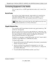
...and disables the copper interface. The switch selects the first connected interface. Insert the SFP module into the connector. 2. Hardware Installation 3-7 v1.0, March 2006 Managed Layer 2 Switches GSM7212, GSM7224, and GSM7248 Hardware Installation Guide Connecting Equipment to the Switch You can install an SFP Gigabit Ethernet...repeat step 1. Note: Ethernet specifications limit the cable length between the switch and the attached device to ensure that is compatible with an RJ-45 connector. Four ports on the switch can be used for management, use one of the management interfaces (...
...and disables the copper interface. The switch selects the first connected interface. Insert the SFP module into the connector. 2. Hardware Installation 3-7 v1.0, March 2006 Managed Layer 2 Switches GSM7212, GSM7224, and GSM7248 Hardware Installation Guide Connecting Equipment to the Switch You can install an SFP Gigabit Ethernet...repeat step 1. Note: Ethernet specifications limit the cable length between the switch and the attached device to ensure that is compatible with an RJ-45 connector. Four ports on the switch can be used for management, use one of the management interfaces (...
GSM7212 Hardware manual
Page 24
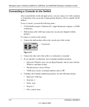
... Baud rate: 9,600 bps • Data bits: 8 • Parity: none • Stop bit: 1 • Flow control: none 3-8 Hardware Installation v1.0, March 2006 To use a console, you attached a workstation, start a terminal-emulation program. • Microsoft Windows users can use HyperTerminal, which comes with a... the Command Line Interface (CLI) to identify the IP address. Managed Layer 2 Switches GSM7212, GSM7224, and GSM7248 Hardware Installation Guide Connecting a Console to the Switch After you install the switch and apply power, you can connect to the console port of the cable to the...
... Baud rate: 9,600 bps • Data bits: 8 • Parity: none • Stop bit: 1 • Flow control: none 3-8 Hardware Installation v1.0, March 2006 To use a console, you attached a workstation, start a terminal-emulation program. • Microsoft Windows users can use HyperTerminal, which comes with a... the Command Line Interface (CLI) to identify the IP address. Managed Layer 2 Switches GSM7212, GSM7224, and GSM7248 Hardware Installation Guide Connecting a Console to the Switch After you install the switch and apply power, you can connect to the console port of the cable to the...

GSM7212 Hardware manual
Page 25
Hardware Installation 3-9 v1.0, March 2006 Managed Layer 2 Switches GSM7212, GSM7224, and GSM7248 Hardware Installation Guide After you connect a console to the switch, you will need to use the CLI, and is located on the NETGEAR CD. • Administration Manual for the 7200 Series Layer-2 Switches: Describes configuration tasks, and is located on the NETGEAR CD. The following documents...
Hardware Installation 3-9 v1.0, March 2006 Managed Layer 2 Switches GSM7212, GSM7224, and GSM7248 Hardware Installation Guide After you connect a console to the switch, you will need to use the CLI, and is located on the NETGEAR CD. • Administration Manual for the 7200 Series Layer-2 Switches: Describes configuration tasks, and is located on the NETGEAR CD. The following documents...

GSM7212 Hardware manual
Page 26
Managed Layer 2 Switches GSM7212, GSM7224, and GSM7248 Hardware Installation Guide 3-10 v1.0, March 2006 Hardware Installation
Managed Layer 2 Switches GSM7212, GSM7224, and GSM7248 Hardware Installation Guide 3-10 v1.0, March 2006 Hardware Installation
