GSM7212 Hardware manual
Page 10
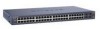
... receptacle for GSM7212 LED Description Power Mode MaxSpd (maximum speed), ACT (activity) or FDX Link (port number) SFP Port (1,000 Mbps only) • Green: Power is supplied, and the switch is operating normally. • Yellow: Power supply present, but it has failed. •... detected. Power receptacle Figure 2-2 2-2 v1.0, March 2006 Introduction Managed Layer 2 Switches GSM7212, GSM7224, and GSM7248 Hardware Installation Guide The following table describes the LEDs on the port.. • Solid green: Link is up. • Blinking green: The port is sending or receiving packets in...
... receptacle for GSM7212 LED Description Power Mode MaxSpd (maximum speed), ACT (activity) or FDX Link (port number) SFP Port (1,000 Mbps only) • Green: Power is supplied, and the switch is operating normally. • Yellow: Power supply present, but it has failed. •... detected. Power receptacle Figure 2-2 2-2 v1.0, March 2006 Introduction Managed Layer 2 Switches GSM7212, GSM7224, and GSM7248 Hardware Installation Guide The following table describes the LEDs on the port.. • Solid green: Link is up. • Blinking green: The port is sending or receiving packets in...
GSM7212 Hardware manual
Page 11
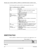
SFP port (1,000 Mbps only) • Solid green: Link is up. • Blinking green: The port is sending or receiving packets in 10 Mbps. Introduction 2-3 v1.0, March 2006 Managed Layer 2 Switches GSM7212, GSM7224, and GSM7248 Hardware Installation Guide GSM7224 Front Panel and LEDs The following table ... port Figure 2-3 The following figure shows the front panel of the switch. The front panel contains LEDs, RJ-45 jacks, and SFP module bays. Link/ACT (left) • Green: Link is up status. • Off: No link is disconnected. 10/100/1000 ports (two LEDs) Speed (right)...
SFP port (1,000 Mbps only) • Solid green: Link is up. • Blinking green: The port is sending or receiving packets in 10 Mbps. Introduction 2-3 v1.0, March 2006 Managed Layer 2 Switches GSM7212, GSM7224, and GSM7248 Hardware Installation Guide GSM7224 Front Panel and LEDs The following table ... port Figure 2-3 The following figure shows the front panel of the switch. The front panel contains LEDs, RJ-45 jacks, and SFP module bays. Link/ACT (left) • Green: Link is up status. • Off: No link is disconnected. 10/100/1000 ports (two LEDs) Speed (right)...

GSM7212 Hardware manual
Page 13
... is sending or receiving packets. • Off: No link is detected. • Solid green: Link is up. • Blinking green: The port is sending or receiving packets in link up status. • Off: No link is detected. Managed Layer 2 Switches GSM7212, GSM7224, and GSM7248 Hardware Installation Guide Table 2-3. GSM7248 Rear Panel The rear panel has a standard AC...
... is sending or receiving packets. • Off: No link is detected. • Solid green: Link is up. • Blinking green: The port is sending or receiving packets in link up status. • Off: No link is detected. Managed Layer 2 Switches GSM7212, GSM7224, and GSM7248 Hardware Installation Guide Table 2-3. GSM7248 Rear Panel The rear panel has a standard AC...
GSM7212 Hardware manual
Page 27
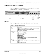
... all products are correct and comply with Ethernet specifications. Troubleshooting Problem Power LED is a problem. Link LED is not working. Check the crimp on the switch and the connected device are correct and comply with Ethernet specifications. Chapter 4 Troubleshooting Troubleshooting Chart The...4-1. Cause No power is received Port connection is off . See Appendix A, "Technical Specifications". Check for the switch at the switch and at both the switch and the connecting device. Make sure that the plug is set to auto-negotiate. Troubleshooting 4-1 v1.0, March 2006
... all products are correct and comply with Ethernet specifications. Troubleshooting Problem Power LED is a problem. Link LED is not working. Check the crimp on the switch and the connected device are correct and comply with Ethernet specifications. Chapter 4 Troubleshooting Troubleshooting Chart The...4-1. Cause No power is received Port connection is off . See Appendix A, "Technical Specifications". Check for the switch at the switch and at both the switch and the connecting device. Make sure that the plug is set to auto-negotiate. Troubleshooting 4-1 v1.0, March 2006

GSM7212 Hardware manual
Page 29
The gigabit port on the gigabit module negotiates speed, duplex mode, and flow control, provided that the attached device supports auto-negotiation. Troubleshooting 4-3 v1.0, March 2006 If the device does not support auto-negotiation, the switch only determines the speed correctly and the duplex mode defaults to half-duplex. Managed Layer 2 Switches GSM7212, GSM7224, and GSM7248 Hardware Installation Guide Auto-Negotiation The 10/100/1000 Mbps ports negotiate the correct duplex mode and speed if the device at the other end of the link supports auto-negotiation.
The gigabit port on the gigabit module negotiates speed, duplex mode, and flow control, provided that the attached device supports auto-negotiation. Troubleshooting 4-3 v1.0, March 2006 If the device does not support auto-negotiation, the switch only determines the speed correctly and the duplex mode defaults to half-duplex. Managed Layer 2 Switches GSM7212, GSM7224, and GSM7248 Hardware Installation Guide Auto-Negotiation The 10/100/1000 Mbps ports negotiate the correct duplex mode and speed if the device at the other end of the link supports auto-negotiation.
GSM7212 Hardware manual
Page 32
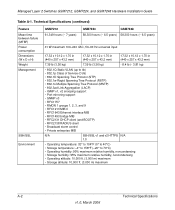
...; 802.1D Spanning Tree Protocol (STP) • 802.1w Rapid Spanning Tree Protocol (RSTP) • 802.1s Multiple Spanning Tree Protocol (MSTP) • 802.3ad Link Aggregation (LACP) • IGMP v1, v2 snooping support • Port mirroring support • SNMP v3 • RFC1757 • RMON 1 groups 1, 2, 3, and 9 • ...noncondensing • Operating altitude: 10,000 ft.( 3,000 m) maximum • Storage altitude: 10,000 ft. (3,000 m) maximum A-2 Technical Specifications v1.0, March 2006 Managed Layer 2 Switches GSM7212, GSM7224, and GSM7248 Hardware Installation Guide Table A-1.
...; 802.1D Spanning Tree Protocol (STP) • 802.1w Rapid Spanning Tree Protocol (RSTP) • 802.1s Multiple Spanning Tree Protocol (MSTP) • 802.3ad Link Aggregation (LACP) • IGMP v1, v2 snooping support • Port mirroring support • SNMP v3 • RFC1757 • RMON 1 groups 1, 2, 3, and 9 • ...noncondensing • Operating altitude: 10,000 ft.( 3,000 m) maximum • Storage altitude: 10,000 ft. (3,000 m) maximum A-2 Technical Specifications v1.0, March 2006 Managed Layer 2 Switches GSM7212, GSM7224, and GSM7248 Hardware Installation Guide Table A-1.

GSM7212 Command line reference manual
Page 13
... traps stpmode 10-6 snmptrap 10-7 snmptrap snmpversion 10-8 10.1.16 snmptrap ipaddr 10-8 10.1.17 snmptrap mode 10-8 10.1.18 snmp trap link-status 10-9 10.1.19 snmp trap link-status all 10-9 10.2 SNMP Show Commands 10-10 10.2.1 show snmpcommunity 10-10 10.2.2 show snmptrap 10-11 10.2.3 show trapflags...
... traps stpmode 10-6 snmptrap 10-7 snmptrap snmpversion 10-8 10.1.16 snmptrap ipaddr 10-8 10.1.17 snmptrap mode 10-8 10.1.18 snmp trap link-status 10-9 10.1.19 snmp trap link-status all 10-9 10.2 SNMP Show Commands 10-10 10.2.1 show snmpcommunity 10-10 10.2.2 show snmptrap 10-11 10.2.3 show trapflags...
GSM7212 Command line reference manual
Page 23
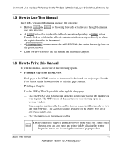
Each page in the HTML version of the manual is described in the manual. •A button to access the full NETGEAR, Inc. Click the PDF of This Chapter link at http://www.adobe.com. - The Acrobat reader is available on a single sheet of paper, you were viewing opens in a ...page. - Double-click on the browser toolbar to view and print PDF files. Use the PDF of This Chapter link at a time. Command Line Interface Reference for the ProSafe 7200 Series Layer-2 Switches, Software Ver- 1.5 How to Use This Manual The HTML version of this manual, choose one of the following ...
Each page in the HTML version of the manual is described in the manual. •A button to access the full NETGEAR, Inc. Click the PDF of This Chapter link at http://www.adobe.com. - The Acrobat reader is available on a single sheet of paper, you were viewing opens in a ...page. - Double-click on the browser toolbar to view and print PDF files. Use the PDF of This Chapter link at a time. Command Line Interface Reference for the ProSafe 7200 Series Layer-2 Switches, Software Ver- 1.5 How to Use This Manual The HTML version of this manual, choose one of the following ...
GSM7212 Command line reference manual
Page 24
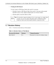
... the top left of the complete manual opens in a browser window. - Click the Complete PDF Manual link at the top left of any page. - Revision History of this manual. Tip: If your printer supports printing of two or ...sheet. 1.7 Revision History Table 1-3 lists the revision history of This Manual Document Part Number 202-10235-01 Revision 1.0 Change Description Document for the ProSafe 7200 Series Layer-2 Switches, Software Ver- • Printing the Full Manual. Table 1-3. Command Line Interface Reference for version 6.0 software release 1-4 About This Manual Publication ...
... the top left of the complete manual opens in a browser window. - Click the Complete PDF Manual link at the top left of any page. - Revision History of this manual. Tip: If your printer supports printing of two or ...sheet. 1.7 Revision History Table 1-3 lists the revision history of This Manual Document Part Number 202-10235-01 Revision 1.0 Change Description Document for the ProSafe 7200 Series Layer-2 Switches, Software Ver- • Printing the Full Manual. Table 1-3. Command Line Interface Reference for version 6.0 software release 1-4 About This Manual Publication ...

GSM7212 Command line reference manual
Page 29
...-channel interfaces. The port identifies the specific physical port or logical interface being managed on physical slots. Port-channel or Link Aggregation Group (LAG) interfaces are logical interfaces that are only used for routing functions. CPU ports are handled by the... logical slots. Type of Ports Port Type Description Physical Ports Logical Interfaces CPU ports The physical ports for the ProSafe 7200 Series Layer-2 Switches, Software Ver- Table 2-2. Parameter Descriptions Parameter Description Logical Interface Character strings Logical slot and port number. Use double...
...-channel interfaces. The port identifies the specific physical port or logical interface being managed on physical slots. Port-channel or Link Aggregation Group (LAG) interfaces are logical interfaces that are only used for routing functions. CPU ports are handled by the... logical slots. Type of Ports Port Type Description Physical Ports Logical Interfaces CPU ports The physical ports for the ProSafe 7200 Series Layer-2 Switches, Software Ver- Table 2-2. Parameter Descriptions Parameter Description Logical Interface Character strings Logical slot and port number. Use double...
GSM7212 Command line reference manual
Page 62
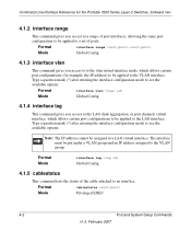
... range - Format interface vlan Mode Global Config 4.1.4 interface lag This command gives you access to the LAG (link aggregation, or port channel) virtual interface, which allows certain port configurations (for the ProSafe 7200 Series Layer-2 Switches, Software Ver- 4.1.2 interface range This command gives you access to to the vlan virtual interface mode, which...
... range - Format interface vlan Mode Global Config 4.1.4 interface lag This command gives you access to the LAG (link aggregation, or port channel) virtual interface, which allows certain port configurations (for the ProSafe 7200 Series Layer-2 Switches, Software Ver- 4.1.2 interface range This command gives you access to to the vlan virtual interface mode, which...

GSM7212 Command line reference manual
Page 68
... VLAN table. Interface(s) This field lists the slot/port interface(s) that the maximum capability of an entry in order for the ProSafe 7200 Series Layer-2 Switches, Software Ver- this port. 4.1.17 show port protocol { | all} Mode Privileged EXEC Group Name This field displays the ... indicates the VLAN associated with this object determines the port's duplex mode and transmission rate. Admin Mode Physical Mode Physical Status Link Status Link Trap LACP Mode Mon - Protocol(s) This field indicates the type of the protocol group. This object determines whether or not ...
... VLAN table. Interface(s) This field lists the slot/port interface(s) that the maximum capability of an entry in order for the ProSafe 7200 Series Layer-2 Switches, Software Ver- this port. 4.1.17 show port protocol { | all} Mode Privileged EXEC Group Name This field displays the ... indicates the VLAN associated with this object determines the port's duplex mode and transmission rate. Admin Mode Physical Mode Physical Status Link Status Link Trap LACP Mode Mon - Protocol(s) This field indicates the type of the protocol group. This object determines whether or not ...

GSM7212 Command line reference manual
Page 69
Command Line Interface Reference for combo port. Physical Status The actual speed and duplex mode Link Status Whether the link is in loop state or not. Loop Status Whether the port is Up or Down. The length of the prompt. Partner Flow Control...Setup Commands 4-9 v1.0, February 2007 The pre-login banner is using TFTP, Xmodem, Ymodem, or Zmodem. Media Type "Copper" or "Fiber" for the ProSafe 7200 Series Layer-2 Switches, Software Ver- 4.1.18 show port status { | all} Mode Privileged Exec Interface Valid slot and port number separated by using flow control or not. ...
Command Line Interface Reference for combo port. Physical Status The actual speed and duplex mode Link Status Whether the link is in loop state or not. Loop Status Whether the port is Up or Down. The length of the prompt. Partner Flow Control...Setup Commands 4-9 v1.0, February 2007 The pre-login banner is using TFTP, Xmodem, Ymodem, or Zmodem. Media Type "Copper" or "Fiber" for the ProSafe 7200 Series Layer-2 Switches, Software Ver- 4.1.18 show port status { | all} Mode Privileged Exec Interface Valid slot and port number separated by using flow control or not. ...

GSM7212 Command line reference manual
Page 94
...sets the path cost for this command sets the external-path cost for that multiple spanning tree instance. You can set based on Link Speed. If you specify an parameter that corresponds to an existing multiple spanning tree instance, the configurations are done for this port ...the external cost as the , the configurations are done for MST instance '0' i.e. You can set based on Link Speed. Command Line Interface Reference for the ProSafe 7200 Series Layer-2 Switches, Software Ver- 5.1.11 spanning-tree max-hops This command sets the MSTP Max Hops parameter to a new ...
...sets the path cost for this command sets the external-path cost for that multiple spanning tree instance. You can set based on Link Speed. If you specify an parameter that corresponds to an existing multiple spanning tree instance, the configurations are done for this port ...the external cost as the , the configurations are done for MST instance '0' i.e. You can set based on Link Speed. Command Line Interface Reference for the ProSafe 7200 Series Layer-2 Switches, Software Ver- 5.1.11 spanning-tree max-hops This command sets the MSTP Max Hops parameter to a new ...

GSM7212 Command line reference manual
Page 95
...this port for mst '0' instance, to the default value, i.e. If you specify cost, this command sets the path cost for the ProSafe 7200 Series Layer-2 Switches, Software Ver- The maximum number of 1 to 4094, that corresponds to the new instance ID to be added. Mode {external-cost ...128. Format spanning-tree mst instance Mode Global Config Spanning Tree Protocol Commands 5-7 v1.0, February 2007 a path cost value based on the Link Speed. Format no spanning-tree mst This command sets the Path Cost or Port Priority for this port within a range of multiple instances ...
...this port for mst '0' instance, to the default value, i.e. If you specify cost, this command sets the path cost for the ProSafe 7200 Series Layer-2 Switches, Software Ver- The maximum number of 1 to 4094, that corresponds to the new instance ID to be added. Mode {external-cost ...128. Format spanning-tree mst instance Mode Global Config Spanning Tree Protocol Commands 5-7 v1.0, February 2007 a path cost value based on the Link Speed. Format no spanning-tree mst This command sets the Path Cost or Port Priority for this port within a range of multiple instances ...

GSM7212 Command line reference manual
Page 104
...link. Link Trap The link trap configuration for the specified interface. 5.2.6 show spanning-tree mst port summary { | all multiple spanning tree instances in the specified spanning tree instance Port Role The role of one or all ports. The configured path cost for the ProSafe 7200 Series Layer-2 Switches... values are displayed. The parameter indicates a particular MST instance. The parameter { | all} indicates the desired switch port or all ports within the spanning tree. Command Line Interface Reference for this port. 5.2.5 show spanning-tree...
...link. Link Trap The link trap configuration for the specified interface. 5.2.6 show spanning-tree mst port summary { | all multiple spanning tree instances in the specified spanning tree instance Port Role The role of one or all ports. The configured path cost for the ProSafe 7200 Series Layer-2 Switches... values are displayed. The parameter indicates a particular MST instance. The parameter { | all} indicates the desired switch port or all ports within the spanning tree. Command Line Interface Reference for this port. 5.2.5 show spanning-tree...

GSM7212 Command line reference manual
Page 153
Table 9-1. Command Line Interface Reference for the ProSafe 7200 Series Layer-2 Switches, Software Ver- 9.1.10 show port-security violation Mode Privileged EXEC MAC Address MAC Address of discarded packet on any Ethernet port exceeds the high ...security violation This command displays the source MAC address of the last packet that was discarded on the port when the amount of the link speed, the switch discards the broadcasts traffic until the broadcast traffic returns to configure storm control and view stormcontrol configuration information. If the broadcast traffic on ...
Table 9-1. Command Line Interface Reference for the ProSafe 7200 Series Layer-2 Switches, Software Ver- 9.1.10 show port-security violation Mode Privileged EXEC MAC Address MAC Address of discarded packet on any Ethernet port exceeds the high ...security violation This command displays the source MAC address of the last packet that was discarded on the port when the amount of the link speed, the switch discards the broadcasts traffic until the broadcast traffic returns to configure storm control and view stormcontrol configuration information. If the broadcast traffic on ...

GSM7212 Command line reference manual
Page 154
... packet storm recovery mode. The thresholds are defined in Table 9-1) of the link speed, the switch discards the broadcasts traffic until the broadcast traffic returns to the low threshold percentage or less. Command Line Interface Reference for the ProSafe 7200 Series Layer-2 Switches, Software Ver- 9.2.1.1 no storm-control broadcast Mode Global Config 9.2.2 storm-control...
... packet storm recovery mode. The thresholds are defined in Table 9-1) of the link speed, the switch discards the broadcasts traffic until the broadcast traffic returns to the low threshold percentage or less. Command Line Interface Reference for the ProSafe 7200 Series Layer-2 Switches, Software Ver- 9.2.1.1 no storm-control broadcast Mode Global Config 9.2.2 storm-control...

GSM7212 Command line reference manual
Page 164
...command disables Multiple User traps. Command Line Interface Reference for the ProSafe 7200 Series Layer-2 Switches, Software Ver- 10.1.11 snmp-server traps linkmode This command enables Link Up/Down traps for the entire switch. Default enabled Format snmp-server traps multiusers Mode Global Config 10... 10-6 v1.0, February 2007 SNMP Commands Format no snmp-server traps linkmode This command disables Link Up/Down traps for the entire switch. Section 10.1.18 "snmp trap link-status" on page 10-9 Default enabled Format snmp-server traps linkmode Mode Global Config 10.1....
...command disables Multiple User traps. Command Line Interface Reference for the ProSafe 7200 Series Layer-2 Switches, Software Ver- 10.1.11 snmp-server traps linkmode This command enables Link Up/Down traps for the entire switch. Default enabled Format snmp-server traps multiusers Mode Global Config 10... 10-6 v1.0, February 2007 SNMP Commands Format no snmp-server traps linkmode This command disables Link Up/Down traps for the entire switch. Section 10.1.18 "snmp trap link-status" on page 10-9 Default enabled Format snmp-server traps linkmode Mode Global Config 10.1....

GSM7212 Command line reference manual
Page 167
... Interface Config 10.1.18.1 no snmp trap link-status Interface Config 10.1.19 snmp trap link-status all This command enables link status traps for the ProSafe 7200 Series Layer-2 Switches, Software Ver- 10.1.18 snmp trap link-status This command enables link status traps by interface. See 'snmp-server enable traps linkmode' command). Note: This command...
... Interface Config 10.1.18.1 no snmp trap link-status Interface Config 10.1.19 snmp trap link-status all This command enables link status traps for the ProSafe 7200 Series Layer-2 Switches, Software Ver- 10.1.18 snmp trap link-status This command enables link status traps by interface. See 'snmp-server enable traps linkmode' command). Note: This command...