GSM7212 Hardware manual
Page 7
... input Screen text, file and server names, extensions, commands, IP addresses This guide uses the following typographical conventions: Table 1-1. Audience, Conventions, Formats, and Scope This guide is used to highlight a procedure that will save time or resources. Warning: Ignoring... interest. Chapter 1 About This Manual The Managed Layer 2 Switches GSM7212, GSM7224, and GSM7248 Hardware Installation Guide contains information for network managers familiar with network management concepts and terminology This guide uses the following formats to highlight special messages: Note: This...
... input Screen text, file and server names, extensions, commands, IP addresses This guide uses the following typographical conventions: Table 1-1. Audience, Conventions, Formats, and Scope This guide is used to highlight a procedure that will save time or resources. Warning: Ignoring... interest. Chapter 1 About This Manual The Managed Layer 2 Switches GSM7212, GSM7224, and GSM7248 Hardware Installation Guide contains information for network managers familiar with network management concepts and terminology This guide uses the following formats to highlight special messages: Note: This...
GSM7212 Hardware manual
Page 8
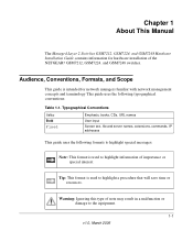
... version Manual publication date • ProSafe 12-Port Gigabit L2 Managed Switch Model GSM7212 • ProSafe 24-Port Gigabit L2 Managed Switch Model GSM7224 • ProSafe 48-Port Gigabit L2 Managed Switch Model GSM7248 March 2006 Note: Product updates are available on the NETGEAR, Inc. Managed Layer 2 Switches GSM7212, GSM7224, and GSM7248 Hardware Installation Guide Danger: This is written according to...
... version Manual publication date • ProSafe 12-Port Gigabit L2 Managed Switch Model GSM7212 • ProSafe 24-Port Gigabit L2 Managed Switch Model GSM7224 • ProSafe 48-Port Gigabit L2 Managed Switch Model GSM7248 March 2006 Note: Product updates are available on the NETGEAR, Inc. Managed Layer 2 Switches GSM7212, GSM7224, and GSM7248 Hardware Installation Guide Danger: This is written according to...

GSM7212 Hardware manual
Page 9
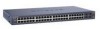
... solution. GSM7212 Front Panel and LEDs The following NETGEAR switches: • ProSafe 12-Port Gigabit L2 Managed Switch Model GSM7212 • ProSafe 24-Port Gigabit L2 Managed Switch Model GSM7224 • ProSafe 48-Port Gigabit L2 Managed Switch Model GSM7248 These switches can use to eliminate bottlenecks, boost performance, and increase productivity. This guide describes the hardware for each product, see...
... solution. GSM7212 Front Panel and LEDs The following NETGEAR switches: • ProSafe 12-Port Gigabit L2 Managed Switch Model GSM7212 • ProSafe 24-Port Gigabit L2 Managed Switch Model GSM7224 • ProSafe 48-Port Gigabit L2 Managed Switch Model GSM7248 These switches can use to eliminate bottlenecks, boost performance, and increase productivity. This guide describes the hardware for each product, see...
GSM7212 Hardware manual
Page 10
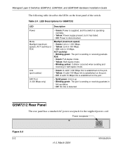
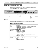
...MaxSpd (maximum speed), ACT (activity) or FDX Link (port number) SFP Port (1,000 Mbps only) • Green: Power is supplied, and the switch is operating normally. • Yellow: Power supply present, but it has failed. • Off: Power is sending or receiving packets in 10 Mbps... established on the port. • Off: A valid 10 Mbps link is established on the front panel of the switch. Table 2-1. Managed Layer 2 Switches GSM7212, GSM7224, and GSM7248 Hardware Installation Guide The following table describes the LEDs on the port.. • Solid green: Link is up status. • Off...
...MaxSpd (maximum speed), ACT (activity) or FDX Link (port number) SFP Port (1,000 Mbps only) • Green: Power is supplied, and the switch is operating normally. • Yellow: Power supply present, but it has failed. • Off: Power is sending or receiving packets in 10 Mbps... established on the port. • Off: A valid 10 Mbps link is established on the front panel of the switch. Table 2-1. Managed Layer 2 Switches GSM7212, GSM7224, and GSM7248 Hardware Installation Guide The following table describes the LEDs on the port.. • Solid green: Link is up status. • Off...
GSM7212 Hardware manual
Page 11
... green: The port is sending or receiving packets. • Off: No link is sending or receiving packets in 10 Mbps. Managed Layer 2 Switches GSM7212, GSM7224, and GSM7248 Hardware Installation Guide GSM7224 Front Panel and LEDs The following table shows the GSM7224 LEDs on the front of the GSM7224. Table 2-2. LEDs RJ-45 jacks...
... green: The port is sending or receiving packets. • Off: No link is sending or receiving packets in 10 Mbps. Managed Layer 2 Switches GSM7212, GSM7224, and GSM7248 Hardware Installation Guide GSM7224 Front Panel and LEDs The following table shows the GSM7224 LEDs on the front of the GSM7224. Table 2-2. LEDs RJ-45 jacks...
GSM7212 Hardware manual
Page 12
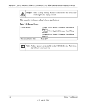
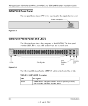
Managed Layer 2 Switches GSM7212, GSM7224, and GSM7248 Hardware Installation Guide GSM7224 Rear Panel The rear panel has a standard AC power receptacle for the supplied power cord. LEDs Figure 2-5 RJ-45 jacks SFP module bays Console port The following figure shows the front panel of the switch. Table 2-3. Power receptacle Figure 2-4 GSM7248 Front Panel and LEDs The...
Managed Layer 2 Switches GSM7212, GSM7224, and GSM7248 Hardware Installation Guide GSM7224 Rear Panel The rear panel has a standard AC power receptacle for the supplied power cord. LEDs Figure 2-5 RJ-45 jacks SFP module bays Console port The following figure shows the front panel of the switch. Table 2-3. Power receptacle Figure 2-4 GSM7248 Front Panel and LEDs The...

GSM7212 Hardware manual
Page 13
...equipment, observe the following safety guidelines to ensure your own personal safety and to electrical shock. GSM7248 Rear Panel The rear panel has a standard AC power receptacle for the supplied power cord. Introduction...marked with the triangular symbol with a lightning bolt may expose you to help protect your system documentation. - GSM7248 LED Description (continued) 10/100/1000 ports (two LEDs) SFP port (1,000 Mbps only) Speed (left)... or receiving packets in 10 Mbps. Managed Layer 2 Switches GSM7212, GSM7224, and GSM7248 Hardware Installation Guide Table 2-3.
...equipment, observe the following safety guidelines to ensure your own personal safety and to electrical shock. GSM7248 Rear Panel The rear panel has a standard AC power receptacle for the supplied power cord. Introduction...marked with the triangular symbol with a lightning bolt may expose you to help protect your system documentation. - GSM7248 LED Description (continued) 10/100/1000 ports (two LEDs) SFP port (1,000 Mbps only) Speed (left)... or receiving packets in 10 Mbps. Managed Layer 2 Switches GSM7212, GSM7224, and GSM7248 Hardware Installation Guide Table 2-3.

GSM7212 Hardware manual
Page 14
If you follow the operating instructions. • Keep your system. Managed Layer 2 Switches GSM7212, GSM7224, and GSM7248 Hardware Installation Guide • If any objects into the product. - Doing so can cause fire or electric shock by shorting out interior components. • Use ...damaged. - An object has fallen into the openings of Europe, the Middle East, and the Far East • Also, be sure the voltage selection switch (if provided) on your location. 2-6 Introduction v1.0, March 2006 The power cable, extension cable, or plug is set to match the power available ...
If you follow the operating instructions. • Keep your system. Managed Layer 2 Switches GSM7212, GSM7224, and GSM7248 Hardware Installation Guide • If any objects into the product. - Doing so can cause fire or electric shock by shorting out interior components. • Use ...damaged. - An object has fallen into the openings of Europe, the Middle East, and the Far East • Also, be sure the voltage selection switch (if provided) on your location. 2-6 Introduction v1.0, March 2006 The power cable, extension cable, or plug is set to match the power available ...
GSM7212 Hardware manual
Page 15
... not exceed 80 percent of all casters and stabilizers are equipped with properly grounded plugs. • Observe extension cable and power strip ratings. Managed Layer 2 Switches GSM7212, GSM7224, and GSM7248 Hardware Installation Guide • Use only approved power cables. ensure that nothing rests on the product. • To help ensure proper grounding.
... not exceed 80 percent of all casters and stabilizers are equipped with properly grounded plugs. • Observe extension cable and power strip ratings. Managed Layer 2 Switches GSM7212, GSM7224, and GSM7248 Hardware Installation Guide • Use only approved power cables. ensure that nothing rests on the product. • To help ensure proper grounding.

GSM7212 Hardware manual
Page 16
Managed Layer 2 Switches GSM7212, GSM7224, and GSM7248 Hardware Installation Guide 2-8 Introduction v1.0, March 2006
Managed Layer 2 Switches GSM7212, GSM7224, and GSM7248 Hardware Installation Guide 2-8 Introduction v1.0, March 2006

GSM7212 Hardware manual
Page 17
... Ethernet Switch models GSM7212, GSM7224, and GSM7248. Documentation including the Command Line Interface Reference for the ProSafe 7200 Series Layer-2 Switches, the Administration Manual for the 7200 Series Layer-2 Switches, the Quick Install Guide, and this Hardware Installation Guide • Warranty and Support Card • Quick Install Guide If you ordered SFP modules with 9-pin connectors • NETGEAR CD...
... Ethernet Switch models GSM7212, GSM7224, and GSM7248. Documentation including the Command Line Interface Reference for the ProSafe 7200 Series Layer-2 Switches, the Administration Manual for the 7200 Series Layer-2 Switches, the Quick Install Guide, and this Hardware Installation Guide • Warranty and Support Card • Quick Install Guide If you ordered SFP modules with 9-pin connectors • NETGEAR CD...

GSM7212 Hardware manual
Page 18
... discharge static electricity from the boxes. When unpacking a static-sensitive component from its shipping carton, leave it on the switch. Place the container on page 3-3. 3. Unpack the hardware from your system. You can also take the following steps ...2006 Unpacking the Hardware Check the contents of the electronic components, such as the microprocessor. Managed Layer 2 Switches GSM7212, GSM7224, and GSM7248 Hardware Installation Guide Protecting Against Electrostatic Discharge Warning: Static electricity can harm delicate components inside your body. 2. Remove all ...
... discharge static electricity from the boxes. When unpacking a static-sensitive component from its shipping carton, leave it on the switch. Place the container on page 3-3. 3. Unpack the hardware from your system. You can also take the following steps ...2006 Unpacking the Hardware Check the contents of the electronic components, such as the microprocessor. Managed Layer 2 Switches GSM7212, GSM7224, and GSM7248 Hardware Installation Guide Protecting Against Electrostatic Discharge Warning: Static electricity can harm delicate components inside your body. 2. Remove all ...
GSM7212 Hardware manual
Page 19
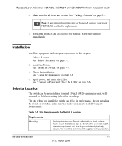
... secure. Install the Switch. Check the installation. See "Connect to Power and Check the LEDs" on page 3-1. Managed Layer 2 Switches GSM7212, GSM7224, and GSM7248 Hardware Installation Guide 4. See "Select a Location" on a tabletop). Select a Location The switch can affect its performance...following site requirements. See "Install the Switch" on page 3-6 4. Before installing the switch or switches, make sure that all items are present. Select a Location. Table 3-1. You need the rack-mount kit supplied with your local NETGEAR reseller for replacement. 5. See "Check...
... secure. Install the Switch. Check the installation. See "Connect to Power and Check the LEDs" on page 3-1. Managed Layer 2 Switches GSM7212, GSM7224, and GSM7248 Hardware Installation Guide 4. See "Select a Location" on a tabletop). Select a Location The switch can affect its performance...following site requirements. See "Install the Switch" on page 3-6 4. Before installing the switch or switches, make sure that all items are present. Select a Location. Table 3-1. You need the rack-mount kit supplied with your local NETGEAR reseller for replacement. 5. See "Check...

GSM7212 Hardware manual
Page 20
...of electrical noise such as direct sunlight, warm air exhausts, hot-air vents, and heaters. Site Requirements for cooling. Install the switch in the room or wiring closet where you access the front panel RJ-45 ports, view the front panel LEDs, and access the... such as radio transmitters, broadcast amplifiers, power lines, and fluorescent lighting fixtures. 3-4 Hardware Installation v1.0, March 2006 Managed Layer 2 Switches GSM7212, GSM7224, and GSM7248 Hardware Installation Guide Table 3-1. Be sure that the AC outlet is 32º to 104ºF (0º to the outlet and the...
...of electrical noise such as direct sunlight, warm air exhausts, hot-air vents, and heaters. Site Requirements for cooling. Install the switch in the room or wiring closet where you access the front panel RJ-45 ports, view the front panel LEDs, and access the... such as radio transmitters, broadcast amplifiers, power lines, and fluorescent lighting fixtures. 3-4 Hardware Installation v1.0, March 2006 Managed Layer 2 Switches GSM7212, GSM7224, and GSM7248 Hardware Installation Guide Table 3-1. Be sure that the AC outlet is 32º to 104ºF (0º to the outlet and the...

GSM7212 Hardware manual
Page 21
... each bracket. Stick one rubber footpad on the bottom of the switch. 2. Managed Layer 2 Switches GSM7212, GSM7224, and GSM7248 Hardware Installation Guide Install the Switch You can install the switch on a Flat Surface The switch ships with four self-adhesive rubber footpads. The rubber footpads cushion the switch against shock and vibrations. Figure 3-1 3. Attach the supplied mounting brackets...
... each bracket. Stick one rubber footpad on the bottom of the switch. 2. Managed Layer 2 Switches GSM7212, GSM7224, and GSM7248 Hardware Installation Guide Install the Switch You can install the switch on a Flat Surface The switch ships with four self-adhesive rubber footpads. The rubber footpads cushion the switch against shock and vibrations. Figure 3-1 3. Attach the supplied mounting brackets...

GSM7212 Hardware manual
Page 22
... equipment thoroughly. 2. Connect to secure the switch in the rack. Connect one end of the AC power adapter cable to a grounded 3-pronged AC outlet. 2. Align the bracket and rack holes. Managed Layer 2 Switches GSM7212, GSM7224, and GSM7248 Hardware Installation Guide 4. Tighten the screws with a No. ...2 Phillips screwdriver to Power and Check the LEDs The switch does not have an ON/OFF switch. Check the Power LED on the front panel of ...
... equipment thoroughly. 2. Connect to secure the switch in the rack. Connect one end of the AC power adapter cable to a grounded 3-pronged AC outlet. 2. Align the bracket and rack holes. Managed Layer 2 Switches GSM7212, GSM7224, and GSM7248 Hardware Installation Guide 4. Tighten the screws with a No. ...2 Phillips screwdriver to Power and Check the LEDs The switch does not have an ON/OFF switch. Check the Power LED on the front panel of ...
GSM7212 Hardware manual
Page 23
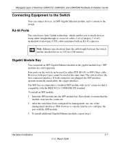
...fiber) cable. However, both connectors are sold separately. To install additional Gigabit Ethernet modules, repeat step 1. Four ports on the switch can be used for management, use one of the management interfaces (Web browser or console interface) to configure the port with the... first connected interface. Insert the SFP module into the connector. 2. Press firmly to the switch. Managed Layer 2 Switches GSM7212, GSM7224, and GSM7248 Hardware Installation Guide Connecting Equipment to the Switch You can connect devices, an SPF Gigabit Ethernet module, and a console to ensure that ...
...fiber) cable. However, both connectors are sold separately. To install additional Gigabit Ethernet modules, repeat step 1. Four ports on the switch can be used for management, use one of the management interfaces (Web browser or console interface) to configure the port with the... first connected interface. Insert the SFP module into the connector. 2. Press firmly to the switch. Managed Layer 2 Switches GSM7212, GSM7224, and GSM7248 Hardware Installation Guide Connecting Equipment to the Switch You can connect devices, an SPF Gigabit Ethernet module, and a console to ensure that ...
GSM7212 Hardware manual
Page 24
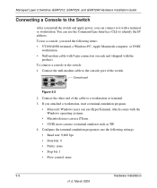
... a terminal or workstation. Connect the null-modem cable to the switch: 1. Connect the other end of the switch. Configure the terminal-emulation program to a workstation or terminal. 3. Managed Layer 2 Switches GSM7212, GSM7224, and GSM7248 Hardware Installation Guide Connecting a Console to the Switch After you install the switch and apply power, you can connect to identify the IP...
... a terminal or workstation. Connect the null-modem cable to the switch: 1. Connect the other end of the switch. Configure the terminal-emulation program to a workstation or terminal. 3. Managed Layer 2 Switches GSM7212, GSM7224, and GSM7248 Hardware Installation Guide Connecting a Console to the Switch After you install the switch and apply power, you can connect to identify the IP...

GSM7212 Hardware manual
Page 25
... both a print document and in PDF format on the NETGEAR CD). • Command Line Interface Reference for the ProSafe 7200 Series Layer-2 Switches: Gives detailed examples of how to configure the switch. Managed Layer 2 Switches GSM7212, GSM7224, and GSM7248 Hardware Installation Guide After you connect a console to the switch, you will need to use the CLI, and is...
... both a print document and in PDF format on the NETGEAR CD). • Command Line Interface Reference for the ProSafe 7200 Series Layer-2 Switches: Gives detailed examples of how to configure the switch. Managed Layer 2 Switches GSM7212, GSM7224, and GSM7248 Hardware Installation Guide After you connect a console to the switch, you will need to use the CLI, and is...

GSM7212 Hardware manual
Page 26
Managed Layer 2 Switches GSM7212, GSM7224, and GSM7248 Hardware Installation Guide 3-10 v1.0, March 2006 Hardware Installation
Managed Layer 2 Switches GSM7212, GSM7224, and GSM7248 Hardware Installation Guide 3-10 v1.0, March 2006 Hardware Installation