FSM726E Hardware Installation Guide
Page 1
Managed Layer 2 Switch with 2 Gigabit Ethernet Ports FSM726E Hardware Installation Guide NETGEAR, Inc. 350 E. Plumeria Drive San Jose, CA 95134 USA 202-10452-02 November 2008
Managed Layer 2 Switch with 2 Gigabit Ethernet Ports FSM726E Hardware Installation Guide NETGEAR, Inc. 350 E. Plumeria Drive San Jose, CA 95134 USA 202-10452-02 November 2008
FSM726E Hardware Installation Guide
Page 6
Managed Layer 2 Switch with 2 Gigabit Ethernet Ports FSM726E Hardware Installation Guide Appendix A Factory Default Settings and Technical Specifications Factory Default Settings A-1 Technical Specifications A-2 vi v1.0, November 2008
Managed Layer 2 Switch with 2 Gigabit Ethernet Ports FSM726E Hardware Installation Guide Appendix A Factory Default Settings and Technical Specifications Factory Default Settings A-1 Technical Specifications A-2 vi v1.0, November 2008
FSM726E Hardware Installation Guide
Page 7
... addresses, GUI screen text URL links • Formats. Tip: This format is intended for readers with 2 Gigabit Ethernet Ports FSM726E Hardware Installation Guide describes how to the equipment. 1 v1.0, November 2008 Warning: Ignoring this manual is used to highlight a procedure that will save...is used to highlight information of note might result in a malfunction or damage to install, configure and troubleshoot the ProSafe 24Port Ethernet L2 Managed Switch Model FSM726E. Conventions, Formats, and Scope The conventions, formats, and scope of this manual are described in this type ...
... addresses, GUI screen text URL links • Formats. Tip: This format is intended for readers with 2 Gigabit Ethernet Ports FSM726E Hardware Installation Guide describes how to the equipment. 1 v1.0, November 2008 Warning: Ignoring this manual is used to highlight a procedure that will save...is used to highlight information of note might result in a malfunction or damage to install, configure and troubleshoot the ProSafe 24Port Ethernet L2 Managed Switch Model FSM726E. Conventions, Formats, and Scope The conventions, formats, and scope of this manual are described in this type ...
FSM726E Hardware Installation Guide
Page 8
...your needs. • Printing a page from PDF. This manual is available on the NETGEAR, Inc. Printing a PDF chapter. Managed Layer 2 Switch with 2 Gigabit Ethernet Ports FSM726E Hardware Installation Guide • Scope. website at a time. , for the product model. •... Links to these specifications: Product Version Manual Publication Date ProSafe 24-Port Ethernet L2 Managed Switch Model FSM726E November 2008 Note...
...your needs. • Printing a page from PDF. This manual is available on the NETGEAR, Inc. Printing a PDF chapter. Managed Layer 2 Switch with 2 Gigabit Ethernet Ports FSM726E Hardware Installation Guide • Scope. website at a time. , for the product model. •... Links to these specifications: Product Version Manual Publication Date ProSafe 24-Port Ethernet L2 Managed Switch Model FSM726E November 2008 Note...
FSM726E Hardware Installation Guide
Page 9
.... • Click the print icon in the upper left corner of any page in the chapter you want to print. Managed Layer 2 Switch with 2 Gigabit Ethernet Ports FSM726E Hardware Installation Guide • Click the PDF of This Chapter link at the top left of your printer supports printing two pages on a single sheet...
.... • Click the print icon in the upper left corner of any page in the chapter you want to print. Managed Layer 2 Switch with 2 Gigabit Ethernet Ports FSM726E Hardware Installation Guide • Click the PDF of This Chapter link at the top left of your printer supports printing two pages on a single sheet...

FSM726E Hardware Installation Guide
Page 10
Managed Layer 2 Switch with 2 Gigabit Ethernet Ports FSM726E Hardware Installation Guide 4 v1.0, November 2008
Managed Layer 2 Switch with 2 Gigabit Ethernet Ports FSM726E Hardware Installation Guide 4 v1.0, November 2008
FSM726E Hardware Installation Guide
Page 11
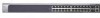
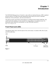
...-standing, or rack-mounted in a wiring closet or an equipment room. The switch can use to eliminate bottlenecks, boost performance, and increase productivity. This guide describes the ProSafe 24-Port Ethernet L2 Managed Switch Model FSM726E. It contains LEDs, RJ-45 jacks, and SFP module bays. Chapter 1 Introduction The NETGEAR Managed Layer 2 Switch is a state-of the...
...-standing, or rack-mounted in a wiring closet or an equipment room. The switch can use to eliminate bottlenecks, boost performance, and increase productivity. This guide describes the ProSafe 24-Port Ethernet L2 Managed Switch Model FSM726E. It contains LEDs, RJ-45 jacks, and SFP module bays. Chapter 1 Introduction The NETGEAR Managed Layer 2 Switch is a state-of the...
FSM726E Hardware Installation Guide
Page 12
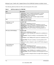
Managed Layer 2 Switch with 2 Gigabit Ethernet Ports FSM726E Hardware Installation Guide The following table describes the LEDs on the port. • Solid green. POST, CPU, or power supply has failed • Off. No link is established on the front panel of the switch. Link/ACT LED • Off: No link is ... sending or receiving packets at 100 Mbps. • If port 25-26 media is established on the port. • Blinking Yellow. LED Descriptions for FSM726E LED PWR (Power) FAN 10/100 (port 1 to Off status. Link/ACT LED • Off. The port is sending or receiving packets at...
Managed Layer 2 Switch with 2 Gigabit Ethernet Ports FSM726E Hardware Installation Guide The following table describes the LEDs on the port. • Solid green. POST, CPU, or power supply has failed • Off. No link is established on the front panel of the switch. Link/ACT LED • Off: No link is ... sending or receiving packets at 100 Mbps. • If port 25-26 media is established on the port. • Blinking Yellow. LED Descriptions for FSM726E LED PWR (Power) FAN 10/100 (port 1 to Off status. Link/ACT LED • Off. The port is sending or receiving packets at...
FSM726E Hardware Installation Guide
Page 13
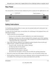
...fallen into the product. - Opening or removing covers that are marked with the triangular symbol with 2 Gigabit Ethernet Ports FSM726E Hardware Installation Guide Rear Panel The rear panel has a console port and a standard AC power receptacle for the supplied power cord. Only ...operate the product in a wet environment. The product has been dropped or damaged. - Introduction 1-3 v1.0, November 2008 Managed Layer 2 Switch with a lightning bolt could expose you follow service markings. - Console port Power receptacle Figure 2 Safety Instructions Use the following conditions ...
...fallen into the product. - Opening or removing covers that are marked with the triangular symbol with 2 Gigabit Ethernet Ports FSM726E Hardware Installation Guide Rear Panel The rear panel has a console port and a standard AC power receptacle for the supplied power cord. Only ...operate the product in a wet environment. The product has been dropped or damaged. - Introduction 1-3 v1.0, November 2008 Managed Layer 2 Switch with a lightning bolt could expose you follow service markings. - Console port Power receptacle Figure 2 Safety Instructions Use the following conditions ...

FSM726E Hardware Installation Guide
Page 14
... at your location. • Use only approved power cables. The voltage and current rating of your country. Make sure that the voltage selection switch (if provided) on any objects into the openings of the cable should be rated for the product and for the voltage and current marked on...the type of power source required, consult your service provider or local power company. • To help protect your system from a cable. Managed Layer 2 Switch with 2 Gigabit Ethernet Ports FSM726E Hardware Installation Guide • Do not push any cables. 1-4 Introduction v1.0, November 2008
... at your location. • Use only approved power cables. The voltage and current rating of your country. Make sure that the voltage selection switch (if provided) on any objects into the openings of the cable should be rated for the product and for the voltage and current marked on...the type of power source required, consult your service provider or local power company. • To help protect your system from a cable. Managed Layer 2 Switch with 2 Gigabit Ethernet Ports FSM726E Hardware Installation Guide • Do not push any cables. 1-4 Introduction v1.0, November 2008

FSM726E Hardware Installation Guide
Page 15
ensure that all casters and stabilizers are firmly connected to the system. Introduction 1-5 v1.0, November 2008 Managed Layer 2 Switch with care; Avoid sudden stops and uneven surfaces. Consult a licensed electrician or your power company for site modifications. • Always follow your local and national wiring rules. • Move products with 2 Gigabit Ethernet Ports FSM726E Hardware Installation Guide • Do not modify power cables or plugs.
ensure that all casters and stabilizers are firmly connected to the system. Introduction 1-5 v1.0, November 2008 Managed Layer 2 Switch with care; Avoid sudden stops and uneven surfaces. Consult a licensed electrician or your power company for site modifications. • Always follow your local and national wiring rules. • Move products with 2 Gigabit Ethernet Ports FSM726E Hardware Installation Guide • Do not modify power cables or plugs.

FSM726E Hardware Installation Guide
Page 16
Managed Layer 2 Switch with 2 Gigabit Ethernet Ports FSM726E Hardware Installation Guide 1-6 Introduction v1.0, November 2008
Managed Layer 2 Switch with 2 Gigabit Ethernet Ports FSM726E Hardware Installation Guide 1-6 Introduction v1.0, November 2008

FSM726E Hardware Installation Guide
Page 17
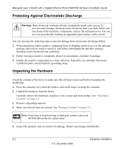
...Series Layer-2 Switches, and this Hardware Installation Guide • Warranty and Support Card If you ordered SFP modules with 9-pin connectors • Resource CD: The CD contains - If any item is packed and shipped separately. Package Contents The switch is missing or damaged, contact your switch, they are...-232) with your place of purchase immediately. 2-1 v1.0, November 2008 Documentation including the Command Line Interface Reference for the ProSafe 7200 Series Layer-2 Switches, the Administration Manual for the Managed Layer 2 Fast Ethernet Switch model FSM726E. MIB files -
...Series Layer-2 Switches, and this Hardware Installation Guide • Warranty and Support Card If you ordered SFP modules with 9-pin connectors • Resource CD: The CD contains - If any item is packed and shipped separately. Package Contents The switch is missing or damaged, contact your switch, they are...-232) with your place of purchase immediately. 2-1 v1.0, November 2008 Documentation including the Command Line Interface Reference for the ProSafe 7200 Series Layer-2 Switches, the Administration Manual for the Managed Layer 2 Fast Ethernet Switch model FSM726E. MIB files -
FSM726E Hardware Installation Guide
Page 18
... present before unwrapping the antistatic package, discharge static electricity from your local NETGEAR reseller for damage. To prevent static damage, discharge static electricity from your system. See "Selecting a Location" on the switch. Managed Layer 2 Switch with 2 Gigabit Ethernet Ports FSM726E Hardware Installation Guide Protecting Against Electrostatic Discharge Warning: Static electricity can also take the following...
... present before unwrapping the antistatic package, discharge static electricity from your local NETGEAR reseller for damage. To prevent static damage, discharge static electricity from your system. See "Selecting a Location" on the switch. Managed Layer 2 Switch with 2 Gigabit Ethernet Ports FSM726E Hardware Installation Guide Protecting Against Electrostatic Discharge Warning: Static electricity can also take the following...
FSM726E Hardware Installation Guide
Page 19
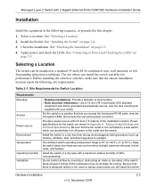
...°C). See "Selecting a Location. 2. Hardware Installation 2-3 v1.0, November 2008 Install the switch in a dry area with your switch. Managed Layer 2 Switch with 2 Gigabit Ethernet Ports FSM726E Hardware Installation Guide Installation Install the equipment in the following site requirements. Select a Location. Site Requirements for Switch Location Requirements Mounting Access Power source Environment Temperature Operating humidity Ventilation •...
...°C). See "Selecting a Location. 2. Hardware Installation 2-3 v1.0, November 2008 Install the switch in a dry area with your switch. Managed Layer 2 Switch with 2 Gigabit Ethernet Ports FSM726E Hardware Installation Guide Installation Install the equipment in the following site requirements. Select a Location. Site Requirements for Switch Location Requirements Mounting Access Power source Environment Temperature Operating humidity Ventilation •...
FSM726E Hardware Installation Guide
Page 20
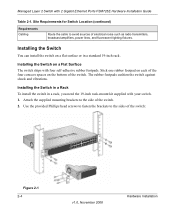
...spaces on the bottom of the switch. 2. Managed Layer 2 Switch with your switch. 1. Installing the Switch You can install the switch on a Flat Surface The switch ships with four self-adhesive rubber...the switch. Use the provided Phillips head screws to fasten the brackets to avoid sources of the switch: Figure 2-1 2-4 v1.0, November 2008 Hardware Installation Site Requirements for Switch Location...power lines, and fluorescent lighting fixtures. Installing the Switch in a Rack To install the switch in a standard 19-inch rack. Installing the Switch on a flat surface or in a rack, you...
...spaces on the bottom of the switch. 2. Managed Layer 2 Switch with your switch. 1. Installing the Switch You can install the switch on a Flat Surface The switch ships with four self-adhesive rubber...the switch. Use the provided Phillips head screws to fasten the brackets to avoid sources of the switch: Figure 2-1 2-4 v1.0, November 2008 Hardware Installation Site Requirements for Switch Location...power lines, and fluorescent lighting fixtures. Installing the Switch in a Rack To install the switch in a standard 19-inch rack. Installing the Switch on a flat surface or in a rack, you...

FSM726E Hardware Installation Guide
Page 21
... that all cables are not damaged and will not create a safety hazard. 4. Managed Layer 2 Switch with nylon washers to fasten each bracket. 4. Inspect the equipment thoroughly. 2. Use two pan-head screws with 2 Gigabit Ethernet Ports FSM726E Hardware Installation Guide 3. Connecting to connect or disconnect the power cord. For help with a No. 1 Phillips screwdriver...
... that all cables are not damaged and will not create a safety hazard. 4. Managed Layer 2 Switch with nylon washers to fasten each bracket. 4. Inspect the equipment thoroughly. 2. Use two pan-head screws with 2 Gigabit Ethernet Ports FSM726E Hardware Installation Guide 3. Connecting to connect or disconnect the power cord. For help with a No. 1 Phillips screwdriver...
FSM726E Hardware Installation Guide
Page 22
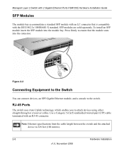
... the attached device to ensure that is compatible with an RJ-45 connector. Managed Layer 2 Switch with 2 Gigabit Ethernet Ports FSM726E Hardware Installation Guide SFP Modules The module bay accommodates a standard SFP module with an LC connector that the module seats into the module bay. Use a Category 5 (Cat5) unshielded ...
... the attached device to ensure that is compatible with an RJ-45 connector. Managed Layer 2 Switch with 2 Gigabit Ethernet Ports FSM726E Hardware Installation Guide SFP Modules The module bay accommodates a standard SFP module with an LC connector that the module seats into the module bay. Use a Category 5 (Cat5) unshielded ...
FSM726E Hardware Installation Guide
Page 23
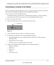
... can use the Command Line Interface (CLI) to identify the IP address. Managed Layer 2 Switch with 2 Gigabit Ethernet Ports FSM726E Hardware Installation Guide Connecting a Console to the Switch After you install the switch and apply power, you can connect to it with the product). To use a console, you attached a ... ZTerm. • UNIX users can use a terminal emulator such as TIP. 4. Connect the null-modem cable to the console port of the cable to the switch: 1. If you need the following settings: • Baud rate: 9,600 bps • Data bits: 8 • Parity: none • Stop bit...
... can use the Command Line Interface (CLI) to identify the IP address. Managed Layer 2 Switch with 2 Gigabit Ethernet Ports FSM726E Hardware Installation Guide Connecting a Console to the Switch After you install the switch and apply power, you can connect to it with the product). To use a console, you attached a ... ZTerm. • UNIX users can use a terminal emulator such as TIP. 4. Connect the null-modem cable to the console port of the cable to the switch: 1. If you need the following settings: • Baud rate: 9,600 bps • Data bits: 8 • Parity: none • Stop bit...

FSM726E Hardware Installation Guide
Page 24
The following documents are provided for this purpose: • Command Line Interface Reference for the 7200 Series Layer-2 Switches: Describes configuration tasks, and is located on the Resource CD. 2-8 Hardware Installation v1.0, November 2008 Managed Layer 2 Switch with 2 Gigabit Ethernet Ports FSM726E Hardware Installation Guide After you connect a console to the switch, you will need to use the CLI, and is located on the Resource CD. • Administration Manual for the ProSafe 7200 Series Layer-2 Switches: Gives detailed examples of how to configure the switch.
The following documents are provided for this purpose: • Command Line Interface Reference for the 7200 Series Layer-2 Switches: Describes configuration tasks, and is located on the Resource CD. 2-8 Hardware Installation v1.0, November 2008 Managed Layer 2 Switch with 2 Gigabit Ethernet Ports FSM726E Hardware Installation Guide After you connect a console to the switch, you will need to use the CLI, and is located on the Resource CD. • Administration Manual for the ProSafe 7200 Series Layer-2 Switches: Gives detailed examples of how to configure the switch.