Installation Guide
Page 2
.... Warning: This is operated in a residential area is declared by NETGEAR, Inc. Bestätigung des Herstellers/Importeurs Es wird hiermit bestätigt, daß das NETGEAR Model FE104 and Model FE108 Fast Ethernet Hubs gemäß der im BMPT-AmtsblVfg 243/1991 und Vfg 46...is not installed and used in which case users will be required to take appropriate measures. NETGEAR does not assume any liability that the NETGEAR Model FE104 and Model FE108 Fast Ethernet Hubs are trademarks or registered trademarks of this product may cause radio interference, in accordance with the ...
.... Warning: This is operated in a residential area is declared by NETGEAR, Inc. Bestätigung des Herstellers/Importeurs Es wird hiermit bestätigt, daß das NETGEAR Model FE104 and Model FE108 Fast Ethernet Hubs gemäß der im BMPT-AmtsblVfg 243/1991 und Vfg 46...is not installed and used in which case users will be required to take appropriate measures. NETGEAR does not assume any liability that the NETGEAR Model FE104 and Model FE108 Fast Ethernet Hubs are trademarks or registered trademarks of this product may cause radio interference, in accordance with the ...
Installation Guide
Page 7
... FE104 Fast Ethernet Hub 2-1 Front panel of the Model FE108 Fast Ethernet Hub 2-2 Link/Rx and Part (partition) LEDs on the RJ-45 ports 2-4 Normal/Uplink push button 2-4 Rear panel of the Model FE104 hub 2-5 Rear panel of the Model FE108 hub 2-6 Daisy-chaining two Model FE108 hubs 3-4 Connecting multiple hubs 3-5 Model FE104 and Model FE108 hubs as standalone hubs 5-2 Using the Model FE104 hub...
... FE104 Fast Ethernet Hub 2-1 Front panel of the Model FE108 Fast Ethernet Hub 2-2 Link/Rx and Part (partition) LEDs on the RJ-45 ports 2-4 Normal/Uplink push button 2-4 Rear panel of the Model FE104 hub 2-5 Rear panel of the Model FE108 hub 2-6 Daisy-chaining two Model FE108 hubs 3-4 Connecting multiple hubs 3-5 Model FE104 and Model FE108 hubs as standalone hubs 5-2 Using the Model FE104 hub...
Installation Guide
Page 11
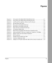
...more bandwidth than the conventional 10BASE-T network. By installing the Model FE104 or Model FE108 hub in your purchase of basic Ethernet • Familiarity with a low-cost, high-performance network solution ...hubs, connecting Fast Ethernet stations, and making network connections. It includes physical configuration guidelines for individuals who are designed to install and use the hubs. Users who have the following background and experience: • Working knowledge of the NETGEAR™ Model FE104 4-port Fast Ethernet Hub or the NETGEAR Model FE108 8-port Fast Ethernet Hub...
...more bandwidth than the conventional 10BASE-T network. By installing the Model FE104 or Model FE108 hub in your purchase of basic Ethernet • Familiarity with a low-cost, high-performance network solution ...hubs, connecting Fast Ethernet stations, and making network connections. It includes physical configuration guidelines for individuals who are designed to install and use the hubs. Users who have the following background and experience: • Working knowledge of the NETGEAR™ Model FE104 4-port Fast Ethernet Hub or the NETGEAR Model FE108 8-port Fast Ethernet Hub...

Installation Guide
Page 12
... Category 5 unshielded twisted pair (UTP) wiring. - Installation Guide for the Model FE104 and Model FE108 Fast Ethernet Hubs Features The Model FE104 and Model FE108 hubs have the following key features: • IEEE 802.3u standard compliance allows interoperation with all 100BASE-TX Fast Ethernet (100 Mbps) products. • Class II compliance enables network expansion by...
... Category 5 unshielded twisted pair (UTP) wiring. - Installation Guide for the Model FE104 and Model FE108 Fast Ethernet Hubs Features The Model FE104 and Model FE108 hubs have the following key features: • IEEE 802.3u standard compliance allows interoperation with all 100BASE-TX Fast Ethernet (100 Mbps) products. • Class II compliance enables network expansion by...
Installation Guide
Page 13
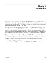
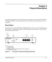
Use the key at the bottom of the Model FE108 hub. 1 2 3 4 5 Pwr Col 100BASE-TX FAST ETHERNET HUB FE104 100 Mbps F AST 1 10 20 >30 Utilization % Link/Rx Part Normal/Uplink 1 2 3 4 Key: 1 = Pwr (power) LED 2 = Col (collision) LED 3 = Utilization % LEDs 4 = RJ-45 ...ports with Link/Rx and Part (partition) LEDs on the front and rear panel components of the Model FE104 Fast Ethernet Hub Physical Description 2-1 Front Panel The front panel contains the LEDs, RJ-45 100BASE-TX port connectors, and Normal/Uplink push button. Front panel of the...
Use the key at the bottom of the Model FE108 hub. 1 2 3 4 5 Pwr Col 100BASE-TX FAST ETHERNET HUB FE104 100 Mbps F AST 1 10 20 >30 Utilization % Link/Rx Part Normal/Uplink 1 2 3 4 Key: 1 = Pwr (power) LED 2 = Col (collision) LED 3 = Utilization % LEDs 4 = RJ-45 ...ports with Link/Rx and Part (partition) LEDs on the front and rear panel components of the Model FE104 Fast Ethernet Hub Physical Description 2-1 Front Panel The front panel contains the LEDs, RJ-45 100BASE-TX port connectors, and Normal/Uplink push button. Front panel of the...

Installation Guide
Page 14
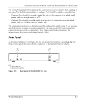
Installation Guide for all ports in the hub • Partition status for the Model FE104 and Model FE108 Fast Ethernet Hubs 1 2 3 4 5 Pwr Col 100BASE-TX FAST ETHERNET HUB FE108 100 Mbps F AST 1 10 20 >30 Utilization % 1 2 3 4 Link/Rx Part Normal/Uplink 5 6 6 8 Key: 1 = Pwr (power) LED 2 = Col (collision) LED 3 = Utilization % LEDs 4 = RJ-45 ports ...
Installation Guide for all ports in the hub • Partition status for the Model FE104 and Model FE108 Fast Ethernet Hubs 1 2 3 4 5 Pwr Col 100BASE-TX FAST ETHERNET HUB FE108 100 Mbps F AST 1 10 20 >30 Utilization % 1 2 3 4 Link/Rx Part Normal/Uplink 5 6 6 8 Key: 1 = Pwr (power) LED 2 = Col (collision) LED 3 = Utilization % LEDs 4 = RJ-45 ports ...

Installation Guide
Page 15
... four RJ-45 100BASE-TX ports, and the Model FE108 provides eight RJ-45 100BASE-TX ports. Installation Guide for the Model FE104 and Model FE108 Fast Ethernet Hubs Table 2-1 describes each LED on the port. The port is an 8-pin connector. RJ-45 100BASE-TX Ports The front panel of Category 5 UTP... cable with a 100 Mbps certified connector. There is data collision on the hub or stack of hubs is incoming data on the ...
... four RJ-45 100BASE-TX ports, and the Model FE108 provides eight RJ-45 100BASE-TX ports. Installation Guide for the Model FE104 and Model FE108 Fast Ethernet Hubs Table 2-1 describes each LED on the port. The port is an 8-pin connector. RJ-45 100BASE-TX Ports The front panel of Category 5 UTP... cable with a 100 Mbps certified connector. There is data collision on the hub or stack of hubs is incoming data on the ...

Installation Guide
Page 16
... When the push button is pressed in, Ports 4 and 8 are configured for the Model FE104 and Model FE108 Fast Ethernet Hubs As illustrated in Figure 2-3, two LEDs are positioned at the top corners of the hub, as illustrated in Figure 2-4, allows you to select uplink (MDI) or normal (MDI-X) wiring for ...normal wiring when the push button is the Part (partition) LED. Both LEDs are configured for Port 4 on the Model FE104 hub and Port 8 on the front panel of each RJ-45 connector. Ports 4 and 8 are described in the out position. Link/Rx and Part (partition)...
... When the push button is pressed in, Ports 4 and 8 are configured for the Model FE104 and Model FE108 Fast Ethernet Hubs As illustrated in Figure 2-3, two LEDs are positioned at the top corners of the hub, as illustrated in Figure 2-4, allows you to select uplink (MDI) or normal (MDI-X) wiring for ...normal wiring when the push button is the Part (partition) LED. Both LEDs are configured for Port 4 on the Model FE104 hub and Port 8 on the front panel of each RJ-45 connector. Ports 4 and 8 are described in the out position. Link/Rx and Part (partition)...
Installation Guide
Page 17
... as a 100 Mbps switch or another normal port, you must use a crossover cable for daisy-chaining or cascading. Installation Guide for the Model FE104 and Model FE108 Fast Ethernet Hubs The Normal/Uplink push button eliminates the need to use an RJ-45 crossover cable to connect the two ports (refer to Appendix...
... as a 100 Mbps switch or another normal port, you must use a crossover cable for daisy-chaining or cascading. Installation Guide for the Model FE104 and Model FE108 Fast Ethernet Hubs The Normal/Uplink push button eliminates the need to use an RJ-45 crossover cable to connect the two ports (refer to Appendix...
Installation Guide
Page 18
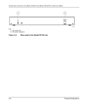
Rear panel of the Model FE108 hub 2 12 Vdc 1.2A -+ 182EA 2-6 Physical Description Installation Guide for the Model FE104 and Model FE108 Fast Ethernet Hubs 1 Key: 1 = Grounding clip 2 = DC power receptacle Figure 2-6.
Rear panel of the Model FE108 hub 2 12 Vdc 1.2A -+ 182EA 2-6 Physical Description Installation Guide for the Model FE104 and Model FE108 Fast Ethernet Hubs 1 Key: 1 = Grounding clip 2 = DC power receptacle Figure 2-6.
Installation Guide
Page 20
... packing materials. Installation Guide for the Model FE104 and Model FE108 Fast Ethernet Hubs Checking Package Contents This package should contain the following items: • Model FE104 or Model FE108 Fast Ethernet Hub • Rubber pads for the location of... purchase and return it to page iii for tabletop installation • DC power adapter • Warranty and Owner Registration Card • This manual Call your reseller or customer support in your area if there are any wrong, missing, or damaged parts. Refer to NETGEAR...
... packing materials. Installation Guide for the Model FE104 and Model FE108 Fast Ethernet Hubs Checking Package Contents This package should contain the following items: • Model FE104 or Model FE108 Fast Ethernet Hub • Rubber pads for the location of... purchase and return it to page iii for tabletop installation • DC power adapter • Warranty and Owner Registration Card • This manual Call your reseller or customer support in your area if there are any wrong, missing, or damaged parts. Refer to NETGEAR...

Installation Guide
Page 21
... Category 5 UTP cable and connectors to follow these steps: 1. Use the guidelines outlined in this chapter. Installation Guide for the Model FE104 and Model FE108 Fast Ethernet Hubs Installing a NETGEAR 100BASE-TX Hub This section provides information and instructions for wiring rules and guidelines. 5. Continue with the steps in "Verifying Your Installation" later in Figure...
... Category 5 UTP cable and connectors to follow these steps: 1. Use the guidelines outlined in this chapter. Installation Guide for the Model FE104 and Model FE108 Fast Ethernet Hubs Installing a NETGEAR 100BASE-TX Hub This section provides information and instructions for wiring rules and guidelines. 5. Continue with the steps in "Verifying Your Installation" later in Figure...

Installation Guide
Page 22
... Guide for the Model FE104 and Model FE108 Fast Ethernet Hubs Installing Multiple Hubs This section provides you have installed your hubs using one of the methods shown, connect the power adapter to the wall, and proceed to a server through the Model FS104 10/100 Mbps Fast Ethernet Switch. In Figure 3-2, multiple hubs are connected to "Verifying...
... Guide for the Model FE104 and Model FE108 Fast Ethernet Hubs Installing Multiple Hubs This section provides you have installed your hubs using one of the methods shown, connect the power adapter to the wall, and proceed to a server through the Model FS104 10/100 Mbps Fast Ethernet Switch. In Figure 3-2, multiple hubs are connected to "Verifying...

Installation Guide
Page 23
... Normal position) 4 = 10 Mbps connection 5 = PCs with 100 Mbps connection to Fast Ethernet hub 6 = PCs with 10 Mbps connection to Ethernet hub 7 = Model FE104 Fast Ethernet Hub (Normal/Uplink push button set in Uplink position) 8 = Model FE108 Fast Ethernet Hub (Normal/Uplink push button set in Uplink position) 9 = Model EN108 Ethernet hub (Normal/Uplink push button set in Uplink position) Figure 3-2.
... Normal position) 4 = 10 Mbps connection 5 = PCs with 100 Mbps connection to Fast Ethernet hub 6 = PCs with 10 Mbps connection to Ethernet hub 7 = Model FE104 Fast Ethernet Hub (Normal/Uplink push button set in Uplink position) 8 = Model FE108 Fast Ethernet Hub (Normal/Uplink push button set in Uplink position) 9 = Model EN108 Ethernet hub (Normal/Uplink push button set in Uplink position) Figure 3-2.

Installation Guide
Page 24
Installation Guide for the Model FE104 and Model FE108 Fast Ethernet Hubs Verifying Your Installation When installation is complete and power has been applied to Chapter 4, "Troubleshooting." 3-6 Installation If there are any problems, refer to the hub, the following conditions should exist: • The Pwr (power) LED on the front panel is on. • The...; The Utilization % LED on the front panel is on and shows the percentage of utilization when data is being received by any port on the hub.
Installation Guide for the Model FE104 and Model FE108 Fast Ethernet Hubs Verifying Your Installation When installation is complete and power has been applied to Chapter 4, "Troubleshooting." 3-6 Installation If there are any problems, refer to the hub, the following conditions should exist: • The Pwr (power) LED on the front panel is on. • The...; The Utilization % LED on the front panel is on and shows the percentage of utilization when data is being received by any port on the hub.
Installation Guide
Page 26
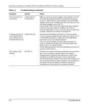
...Mbps LED and Link LEDs are on the network. If you are normal on Ethernet networks and occur when two or more computers transmit data on the front panel. Excessive collisions can result when multiple hubs are connected and when many computers are using a straight-through cable connected to...the Model FE104 hub or with Port 8 on the Model FE108 hub Col (collision) LED blinking Col LED on Check Make sure that the network adapter card installed in the PC is in working condition and that there is installed, and check for the Model FE104 and Model FE108 Fast Ethernet Hubs Table 4-1.
...Mbps LED and Link LEDs are on the network. If you are normal on Ethernet networks and occur when two or more computers transmit data on the front panel. Excessive collisions can result when multiple hubs are connected and when many computers are using a straight-through cable connected to...the Model FE104 hub or with Port 8 on the Model FE108 hub Col (collision) LED blinking Col LED on Check Make sure that the network adapter card installed in the PC is in working condition and that there is installed, and check for the Model FE104 and Model FE108 Fast Ethernet Hubs Table 4-1.

Installation Guide
Page 27
...5 cabling so connections can be used with multiple users or workgroups and other interconnection devices in various configurations. Examples are provided by incorporating NETGEAR Ethernet hubs and switches into your network connections. Chapter 5 Network Configuration This chapter provides an overview of the levels of service that are given to.... These services can be attached to provide flexibility in network environments of 100 Mbps for each user. Configuration Examples The Model FE104 and Model FE108 hubs are designed to any 10 or 100 Mbps...
...5 cabling so connections can be used with multiple users or workgroups and other interconnection devices in various configurations. Examples are provided by incorporating NETGEAR Ethernet hubs and switches into your network connections. Chapter 5 Network Configuration This chapter provides an overview of the levels of service that are given to.... These services can be attached to provide flexibility in network environments of 100 Mbps for each user. Configuration Examples The Model FE104 and Model FE108 hubs are designed to any 10 or 100 Mbps...

Installation Guide
Page 28
...access. As illustrated in Figure 5-2, adding a Model FE104 or Model FE108 hub allows power users to the server. When many local area network (LAN) environments, the primary problem is congestion. By adding a NETGEAR Model SW502 Ethernet Switch that has one 10 Mbps port and one ...server on a 10 Mbps link, congestion and collisions may occur more common problems affecting network performance is access to be used in low data throughput. Installation Guide for the Model FE104 and Model FE108 Fast Ethernet Hubs...
...access. As illustrated in Figure 5-2, adding a Model FE104 or Model FE108 hub allows power users to the server. When many local area network (LAN) environments, the primary problem is congestion. By adding a NETGEAR Model SW502 Ethernet Switch that has one 10 Mbps port and one ...server on a 10 Mbps link, congestion and collisions may occur more common problems affecting network performance is access to be used in low data throughput. Installation Guide for the Model FE104 and Model FE108 Fast Ethernet Hubs...

Installation Guide
Page 29
Installation Guide for the Model FE104 and Model FE108 Fast Ethernet Hubs 7 12 3 Model FE104 hub 4 56 Model SW502 switch 1 2 Model EN516 hub Model EN516 hub Model EN516 hub 8 8 7 7 217EA Key: 1 = PCs with 10 Mbps connections Figure 5-2. Using the Model FE104 hub to migrate your network to Model EN516 Ethernet Hub.) 6 = 10 Mbps connection 7 = Model EN516 Ethernet Hub (Normal/Uplink push button set in Uplink...
Installation Guide for the Model FE104 and Model FE108 Fast Ethernet Hubs 7 12 3 Model FE104 hub 4 56 Model SW502 switch 1 2 Model EN516 hub Model EN516 hub Model EN516 hub 8 8 7 7 217EA Key: 1 = PCs with 10 Mbps connections Figure 5-2. Using the Model FE104 hub to migrate your network to Model EN516 Ethernet Hub.) 6 = 10 Mbps connection 7 = Model EN516 Ethernet Hub (Normal/Uplink push button set in Uplink...

Installation Guide
Page 30
... position) Figure 5-3. Installation Guide for the Model FE104 and Model FE108 Fast Ethernet Hubs Multiport Switch with Fast Ethernet Backbone If the 10 Mbps shared repeater portion of the network experiences congestion, you can use the Model SW507 Ethernet Switch with six 10 Mbps ports and one of... 4 = Server 5 = Model SW507 switch (Normal/Uplink push button set in Uplink position) 6 = 10 Mbps connection 7 = Model EN516 Ethernet Hubs (Normal/Uplink push button set in Figure 5-3, adding the switch increases overall bandwidth and throughput because the traffic from one 10 Mbps segment ...
... position) Figure 5-3. Installation Guide for the Model FE104 and Model FE108 Fast Ethernet Hubs Multiport Switch with Fast Ethernet Backbone If the 10 Mbps shared repeater portion of the network experiences congestion, you can use the Model SW507 Ethernet Switch with six 10 Mbps ports and one of... 4 = Server 5 = Model SW507 switch (Normal/Uplink push button set in Uplink position) 6 = 10 Mbps connection 7 = Model EN516 Ethernet Hubs (Normal/Uplink push button set in Figure 5-3, adding the switch increases overall bandwidth and throughput because the traffic from one 10 Mbps segment ...


