EN104 Installation Guide
Page 10
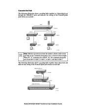
The following illustration shows cascading hubs together in a hierarchical star through the 10BASE-T ports and indicates the setting of the Normal/Uplink push button on each hub. Hub 1 10 BASE-T HUB EN116 Pwr Col 1 2 3 4 5 6 7 8 1 2 3 4 LINK Rx 5 6 7 8 Normal Hub 2 10 BASE-T HUB EN108TP Pwr Col 1 2 3 4 5 6 7 8 Uplink Hub 3 10 BASE-T HUB EN108TP Pwr Col 1 2 3 4 5 6 7 8 Uplink Hub 4 Uplink Hub 5 Uplink A B 8735FA Note: Ethernet specifications limit...
The following illustration shows cascading hubs together in a hierarchical star through the 10BASE-T ports and indicates the setting of the Normal/Uplink push button on each hub. Hub 1 10 BASE-T HUB EN116 Pwr Col 1 2 3 4 5 6 7 8 1 2 3 4 LINK Rx 5 6 7 8 Normal Hub 2 10 BASE-T HUB EN108TP Pwr Col 1 2 3 4 5 6 7 8 Uplink Hub 3 10 BASE-T HUB EN108TP Pwr Col 1 2 3 4 5 6 7 8 Uplink Hub 4 Uplink Hub 5 Uplink A B 8735FA Note: Ethernet specifications limit...


