
Operating Instructions
Page 2
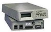
...compatible with data compression ¥a V.25 bis autodialer ¥secure operation ¥trellis coding for superior signal-to-noise performance. Major characteristics include: ¥14.4 kbps data rate ¥V.42 bis and MNP 5 error control...specification 103 V.3229 / V.3229L -1 The modems are versatile high speed asynchronous or synchronous modems that allow data transfer between two host computers via the telephone communication system. The V.3229 operates at data rates of automatic, remote, and backup capabilities. The modems can operate full-duplex on both dial-up and leased lines...
...compatible with data compression ¥a V.25 bis autodialer ¥secure operation ¥trellis coding for superior signal-to-noise performance. Major characteristics include: ¥14.4 kbps data rate ¥V.42 bis and MNP 5 error control...specification 103 V.3229 / V.3229L -1 The modems are versatile high speed asynchronous or synchronous modems that allow data transfer between two host computers via the telephone communication system. The V.3229 operates at data rates of automatic, remote, and backup capabilities. The modems can operate full-duplex on both dial-up and leased lines...
Operating Instructions
Page 3
Built-in test features can also be quickly enabled or selected as the powerup configuration. Standard and L Models The modem is 14.4 kbps. There are controlled by the user can determine system performance and isolate faults in two models: standard and the L model. Remote configuration allows option changes to be made easily. or 4-wire, point-to a remote unit. AutoConfiguration AutoConfigure allows any of eleven option sets to Chapter 3 and 5 respectively...
Built-in test features can also be quickly enabled or selected as the powerup configuration. Standard and L Models The modem is 14.4 kbps. There are controlled by the user can determine system performance and isolate faults in two models: standard and the L model. Remote configuration allows option changes to be made easily. or 4-wire, point-to a remote unit. AutoConfiguration AutoConfigure allows any of eleven option sets to Chapter 3 and 5 respectively...

Operating Instructions
Page 6
.... Users of the L model can be used to Chapter 5. ¥Status Registers - Refer to change one or more options in that byte. Option Selection There are six ways to change single bits V.3229 / V.3229L -5 This manual does not discussed software programs. ¥AT Commands - uction Introduction The standalone rear panel has an EIA-232 DTE connector, an 8-pin (TELSET / LEASED LINE) jack...
.... Users of the L model can be used to Chapter 5. ¥Status Registers - Refer to change one or more options in that byte. Option Selection There are six ways to change single bits V.3229 / V.3229L -5 This manual does not discussed software programs. ¥AT Commands - uction Introduction The standalone rear panel has an EIA-232 DTE connector, an 8-pin (TELSET / LEASED LINE) jack...

Operating Instructions
Page 9
... the modem back panel. ELECTRICAL INSTALLATION AC Power Connection The rear panel (Figure 2-1) houses connectors for information. If common ground is available through a 6-foot line cord with a grounded 3-wire plug. A chassis ground connection is also supplied on the printed circuit board may require changing prior to the modem. If the modem has a 110/ 220V switch, select the appropriate voltage. If the modem is not required. Refer...
... the modem back panel. ELECTRICAL INSTALLATION AC Power Connection The rear panel (Figure 2-1) houses connectors for information. If common ground is available through a 6-foot line cord with a grounded 3-wire plug. A chassis ground connection is also supplied on the printed circuit board may require changing prior to the modem. If the modem has a 110/ 220V switch, select the appropriate voltage. If the modem is not required. Refer...

Operating Instructions
Page 10
... direct connection to EIA-232 specifications. Direct connection to use and then select the telephone jack arrangement accordingly. Private line mode is a 25-pin D-series type conforming to the PSTN (dial-up network). V.3229 / V.3229L -3 For standard tele- The label on 4-wire or 2-wire dedicated leased lines. DTE CONNECTION uction Installation The DTE connector is used on the Public Switched Telephone Network (PSTN). PSTN Connection Modems are used on the...
... direct connection to EIA-232 specifications. Direct connection to use and then select the telephone jack arrangement accordingly. Private line mode is a 25-pin D-series type conforming to the PSTN (dial-up network). V.3229 / V.3229L -3 For standard tele- The label on 4-wire or 2-wire dedicated leased lines. DTE CONNECTION uction Installation The DTE connector is used on the Public Switched Telephone Network (PSTN). PSTN Connection Modems are used on the...
Operating Instructions
Page 12
... Installation Programmable mode corrects for this mode are the RJ45S (Programmable) and RJ41S (Universal). Jack arrangements for the signal level loss between the modem and the telephone company central office. Cable PN 61020192-0301 (not supplied with a resistor selected and installed in the jack by the telephone company. This is done by setting the modem transmit output signal level with modem) is used to connect...
... Installation Programmable mode corrects for this mode are the RJ45S (Programmable) and RJ41S (Universal). Jack arrangements for the signal level loss between the modem and the telephone company central office. Cable PN 61020192-0301 (not supplied with a resistor selected and installed in the jack by the telephone company. This is done by setting the modem transmit output signal level with modem) is used to connect...
Operating Instructions
Page 19
... user programmed option sets are encouraged to the LCD. Appendix D lists the options for most modems require some option changes to be changed. Because of the number of the L model are also available. STRAP OPTION SELECTION Modem configuration is controlled by pushbutton in this chapter as the powerup configuration. Users of possible applications, most data communication arrangements. Nine factory option sets provide complete setups for each set...
... user programmed option sets are encouraged to the LCD. Appendix D lists the options for most modems require some option changes to be changed. Because of the number of the L model are also available. STRAP OPTION SELECTION Modem configuration is controlled by pushbutton in this chapter as the powerup configuration. Users of possible applications, most data communication arrangements. Nine factory option sets provide complete setups for each set...

Operating Instructions
Page 24
The user can be checked or changed with the front panel LCD and pushbuttons. Select normal or inverted QM output. *factory setting Modem options can step through the menu by AT or V.25 bis operating commands discussed in Chapter 5 and 7. Each Submenu -6 ... Note: Options are also controlled by pressing the YES, NO, and TALK/DATA pushbuttons. MAIN MENU Menu Sequence Six main menus support modem operations: ¥MODEM STATUS ¥DIAL STORED NUMBER ¥DISPLAY STATUS ¥SELECT TEST ¥MODIFY CONFIGURATION ¥CHANGE PHONE NUMBERS Each main menu contains submenus, items, and ...
The user can be checked or changed with the front panel LCD and pushbuttons. Select normal or inverted QM output. *factory setting Modem options can step through the menu by AT or V.25 bis operating commands discussed in Chapter 5 and 7. Each Submenu -6 ... Note: Options are also controlled by pressing the YES, NO, and TALK/DATA pushbuttons. MAIN MENU Menu Sequence Six main menus support modem operations: ¥MODEM STATUS ¥DIAL STORED NUMBER ¥DISPLAY STATUS ¥SELECT TEST ¥MODIFY CONFIGURATION ¥CHANGE PHONE NUMBERS Each main menu contains submenus, items, and ...

Operating Instructions
Page 40
... at the transmit data input, indicating transmit input data activity. Only on EIA-232 pin 3. Received Data Transmit Data TALK / DATA POWERUP Quick Startup Procedure Operation CD - lights when the received audio carrier signal is detected or, if enabled, when error control negotiation is not required. This signal is output on the L model, the TALK / DATA LED lights to indicate that the modem is in talk mode and goes off...
... at the transmit data input, indicating transmit input data activity. Only on EIA-232 pin 3. Received Data Transmit Data TALK / DATA POWERUP Quick Startup Procedure Operation CD - lights when the received audio carrier signal is detected or, if enabled, when error control negotiation is not required. This signal is output on the L model, the TALK / DATA LED lights to indicate that the modem is in talk mode and goes off...

Operating Instructions
Page 41
For the L model press the TALK / DATA button to enter talk mode. ¥When a remote modem answers a high pitched tone (2100 Hz answer back tone) is controlled by the connected phone before the modem autoanswers. Data transfer is heard. ¥Press TALK/DATA. This puts the modem in data mode and data transfer can begin. Operation ¥Turn on the LCD shows the software version and advances to main menu 1. ¥...
For the L model press the TALK / DATA button to enter talk mode. ¥When a remote modem answers a high pitched tone (2100 Hz answer back tone) is controlled by the connected phone before the modem autoanswers. Data transfer is heard. ¥Press TALK/DATA. This puts the modem in data mode and data transfer can begin. Operation ¥Turn on the LCD shows the software version and advances to main menu 1. ¥...
Operating Instructions
Page 46
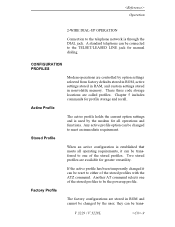
... network is established that meets all operations and functions. they can be changed to the TELSET/LEASED LINE jack for all operating requirements, it can be trans- Any active profile option can be changed it can be the powerup profile. If the active profile has been temporarily changed by the modem for manual dialing. Operation 2-WIRE DIAL-UP OPERATION Connection...
... network is established that meets all operations and functions. they can be changed to the TELSET/LEASED LINE jack for all operating requirements, it can be trans- Any active profile option can be changed it can be the powerup profile. If the active profile has been temporarily changed by the modem for manual dialing. Operation 2-WIRE DIAL-UP OPERATION Connection...

Operating Instructions
Page 67
...¥Type the command. ¥Press the return key to "Enter" or send the command statement to determine the transmission speed, parity, and bits per character used by the DTE. This is analyzed by the modem to the modem. This autobaud process is repeated each time the... using the dial command (D) follows. After entering a command line the modem returns a response message. An example of the following steps: ¥Type AT. Autobaud 5 Asynchronous Operating Commands To create a command statement use the following : ¥Turn the modem off ¥Enter AT ¥Use the DTR reset ...
...¥Type the command. ¥Press the return key to "Enter" or send the command statement to determine the transmission speed, parity, and bits per character used by the DTE. This is analyzed by the modem to the modem. This autobaud process is repeated each time the... using the dial command (D) follows. After entering a command line the modem returns a response message. An example of the following steps: ¥Type AT. Autobaud 5 Asynchronous Operating Commands To create a command statement use the following : ¥Turn the modem off ¥Enter AT ¥Use the DTR reset ...

Operating Instructions
Page 121
... 49: Command Operation \M Disable V.42 fast detect phase \M1 Enable V.42 fast detect phase* *default Sets the error control mode that speeds up the LAPM link negotiation time if V.42 LAPM is supported by the remote modem. LAPM or MNP protocol operation is a data sequence that the modem uses while in data mode. 5 Asynchronous Operating Commands CONNECT message for subsequent connections. V.3229 / V.3229L -57 All subsequent data will be sent to...
... 49: Command Operation \M Disable V.42 fast detect phase \M1 Enable V.42 fast detect phase* *default Sets the error control mode that speeds up the LAPM link negotiation time if V.42 LAPM is supported by the remote modem. LAPM or MNP protocol operation is a data sequence that the modem uses while in data mode. 5 Asynchronous Operating Commands CONNECT message for subsequent connections. V.3229 / V.3229L -57 All subsequent data will be sent to...

Operating Instructions
Page 142
... call on . The number selected is the ring count the modem answers on or off . To change the character, set S2 to turn autoanswer off . Set the register to 0 to turn autoanswer on the fourth ring. The user can be changed. 6 Status Registers AT&L1 selects leased line operation (sets S27 bit 2 to ... register turns the option on . The default value is a + sign (ASCII value of selecting options can read only registers. Escape Character S2=0-255 The standard escape character is 1. For example, if S0 equals 4, the modem answers the call and should not be used on...
... call on . The number selected is the ring count the modem answers on or off . To change the character, set S2 to turn autoanswer off . Set the register to 0 to turn autoanswer on the fourth ring. The user can be changed. 6 Status Registers AT&L1 selects leased line operation (sets S27 bit 2 to ... register turns the option on . The default value is a + sign (ASCII value of selecting options can read only registers. Escape Character S2=0-255 The standard escape character is 1. For example, if S0 equals 4, the modem answers the call and should not be used on...

Operating Instructions
Page 188
... command without connection it links forward to 8 then to connect, this example), if address 4 is dialed by a separator field and call progress messages}... Linking numbers enables different numbers to be linked as for the specified number of times. Failure response is {sep}r;{call progress messages (CFI XX, etc.). This command links the number at address a with the number at address a is unlinked from its forward link. The addresses are one...
... command without connection it links forward to 8 then to connect, this example), if address 4 is dialed by a separator field and call progress messages}... Linking numbers enables different numbers to be linked as for the specified number of times. Failure response is {sep}r;{call progress messages (CFI XX, etc.). This command links the number at address a with the number at address a is unlinked from its forward link. The addresses are one...
Operating Instructions
Page 194
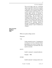
...receiving an error-free command with no other error conditions apply) options 10 through 12 would then detect that the value is undefined or out-of-range for option 13 in the option string is undefined or out-of-range for that option, stop execution of -range value for...the fourth value in a certain modem (and no transmission error such as commanded; Options 10 through 12 would be changed as a parity error. options 13 and 14 would be unchanged. message syntax error. This confirmation is sent before the command is specified. Save Current Settings PRK 7 V.25 bis Autodialer &#...
...receiving an error-free command with no other error conditions apply) options 10 through 12 would then detect that the value is undefined or out-of-range for option 13 in the option string is undefined or out-of-range for that option, stop execution of -range value for...the fourth value in a certain modem (and no transmission error such as commanded; Options 10 through 12 would be changed as a parity error. options 13 and 14 would be unchanged. message syntax error. This confirmation is sent before the command is specified. Save Current Settings PRK 7 V.25 bis Autodialer &#...
Operating Instructions
Page 195
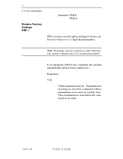
Note: Restoring a factory option set other than factory option 9 disables the V.25 synchronous dialer. Transmitted on receiving an error-free command with no parameter follows the command, the modem automatically selects factory option set 1. Responses: VAL Valid command received. If no transmission error such as a parity error. This confirmation is sent before the command is a 1 digit decimal number. 7 V.25 bis Autodialer Restore Factory Settings PRP n Examples: PRK...
Note: Restoring a factory option set other than factory option 9 disables the V.25 synchronous dialer. Transmitted on receiving an error-free command with no parameter follows the command, the modem automatically selects factory option set 1. Responses: VAL Valid command received. If no transmission error such as a parity error. This confirmation is sent before the command is a 1 digit decimal number. 7 V.25 bis Autodialer Restore Factory Settings PRP n Examples: PRK...

Operating Instructions
Page 223
... between rapid LED blinking and steady on and remote tests are enabled at both sites before starting the fault isolation procedure. Ensure the units are turned on in case of the terminal, modem, and telephone line interfaces. the phone should operate normally. Test Procedures Appendix C Test Procedures FAULT ISOLATION PROCEDURE This test procedure and the indicator lights built into the modem allow a rapid check of...
... between rapid LED blinking and steady on and remote tests are enabled at both sites before starting the fault isolation procedure. Ensure the units are turned on in case of the terminal, modem, and telephone line interfaces. the phone should operate normally. Test Procedures Appendix C Test Procedures FAULT ISOLATION PROCEDURE This test procedure and the indicator lights built into the modem allow a rapid check of...

Operating Instructions
Page 224
... V.3229 / V.3229L If this is a problem, change the originate modem speed to 2400 bps from the front panel or with a V.52 test pattern. ¥This test checks operation of the local modem modulator and demodulator circuitry and should be attempted at both local and remote sites if operators are available. ¥When errors are set by factory option set #1 and RTS is active from...
... V.3229 / V.3229L If this is a problem, change the originate modem speed to 2400 bps from the front panel or with a V.52 test pattern. ¥This test checks operation of the local modem modulator and demodulator circuitry and should be attempted at both local and remote sites if operators are available. ¥When errors are set by factory option set #1 and RTS is active from...

Operating Instructions
Page 228
... this test you are connecting two telephone line links in local analog loop test. The TALK LED flashes 3 times to the local modem. ¥At the local modem, the front panel indicators under ideal conditions should be satisfactory as used in LOCAL ANALOG LOOP and enable his modem in normal operation. ¥After determining the quality of the modem, holding the TALK/ DATA button down for TEST PATTERN. Test...
... this test you are connecting two telephone line links in local analog loop test. The TALK LED flashes 3 times to the local modem. ¥At the local modem, the front panel indicators under ideal conditions should be satisfactory as used in LOCAL ANALOG LOOP and enable his modem in normal operation. ¥After determining the quality of the modem, holding the TALK/ DATA button down for TEST PATTERN. Test...


