User Guide
Page 2
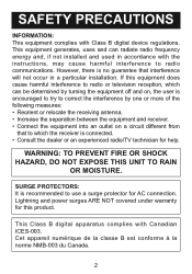
... which the receiver is no guarantee that to radio communications. Lightning and power surges ARE NOT covered under warranty for AC connection. This equipment generates, uses and can radiate radio frequency energy and, if not installed and used in accordance with the ...the following measures: • Reorient or relocate the receiving antenna. • Increase the separation between the equipment and receiver. • Connect the equipment into an outlet on a circuit different from that interference will not occur in a particular installation. If this product. SAFETY PRECAUTIONS...
... which the receiver is no guarantee that to radio communications. Lightning and power surges ARE NOT covered under warranty for AC connection. This equipment generates, uses and can radiate radio frequency energy and, if not installed and used in accordance with the ...the following measures: • Reorient or relocate the receiving antenna. • Increase the separation between the equipment and receiver. • Connect the equipment into an outlet on a circuit different from that interference will not occur in a particular installation. If this product. SAFETY PRECAUTIONS...

User Guide
Page 3
... may not have been adhered to your unit. ATTACHMENTS Do not use attachments not recommended by the manufacturer. 8A. in the operating instructions should be connected to overturn. 9. The product may cause the appliance and cart combination to an outdoor antenna. 1. RETAIN INSTRUCTIONS The safety and operating instructions should be retained...
... may not have been adhered to your unit. ATTACHMENTS Do not use attachments not recommended by the manufacturer. 8A. in the operating instructions should be connected to overturn. 9. The product may cause the appliance and cart combination to an outdoor antenna. 1. RETAIN INSTRUCTIONS The safety and operating instructions should be retained...

User Guide
Page 4
... local power company. This plug will prevent damage to the product due to the operating instructions. 11. POWER LINES An outside antenna is connected to the product, be located in a risk of the polarized plug. 12. This is left unattended and unused for long periods of ...fit, contact your product from touching such power lines or circuits as they exit from the wall outlet and disconnect the antenna or cable system. SAFETY PRECAUTIONS consult your obsolete outlet. GROUNDING OR POLARIZATION This product is grounded so as this product through openings as contact with a...
... local power company. This plug will prevent damage to the product due to the operating instructions. 11. POWER LINES An outside antenna is connected to the product, be located in a risk of the polarized plug. 12. This is left unattended and unused for long periods of ...fit, contact your product from touching such power lines or circuits as they exit from the wall outlet and disconnect the antenna or cable system. SAFETY PRECAUTIONS consult your obsolete outlet. GROUNDING OR POLARIZATION This product is grounded so as this product through openings as contact with a...

User Guide
Page 5
...by a qualified technician to restore the product to dangerous voltage or other hazards. 20. e. HEAT The product should be connected to the grounding system of the NEC that provides guidelines for proper grounding and, in fire, electric shock or other hazards. Unauthorized substitutions may ...70, provides information with respect to proper grounding of the mast and supporting structure, grounding of antenna discharge product, connection to service this indicates a need for grounding electrodes. 18. b. SERVICING Do not attempt to grounding electrodes and requirements for service. 23....
...by a qualified technician to restore the product to dangerous voltage or other hazards. 20. e. HEAT The product should be connected to the grounding system of the NEC that provides guidelines for proper grounding and, in fire, electric shock or other hazards. Unauthorized substitutions may ...70, provides information with respect to proper grounding of the mast and supporting structure, grounding of antenna discharge product, connection to service this indicates a need for grounding electrodes. 18. b. SERVICING Do not attempt to grounding electrodes and requirements for service. 23....

User Guide
Page 11
... the videos/photos on your external TV. 11 OR NOTES: • Set the TV's TV/VIDEO button or switch to the VIDEO setting. • When connecting the unit, refer to the owner's manual of your iPod and set the TV Out setting to ON, otherwise, you can...; Make sure to go into the Settings menu of the TV, as well as this manual. • When connecting the unit, make sure the power is off and both units are using an iPod that has photo/video capability, and your TV has a standard ...
... the videos/photos on your external TV. 11 OR NOTES: • Set the TV's TV/VIDEO button or switch to the VIDEO setting. • When connecting the unit, refer to the owner's manual of your iPod and set the TV Out setting to ON, otherwise, you can...; Make sure to go into the Settings menu of the TV, as well as this manual. • When connecting the unit, make sure the power is off and both units are using an iPod that has photo/video capability, and your TV has a standard ...

User Guide
Page 12
DVD TV DVD: To listen to the DVD player connected to the owner's manual of the TV, as well as this speaker. NOTES: • When connecting the unit, refer to the DVD In jacks, press ...audio player, with audio left and right out jacks. • If your local electronics supply store. 12 INPUT CONNECTIONS Connect a DVD to the DVD Audio In jacks and a TV to the TV Audio In jacks to the TV...until DVD appears in the display. TV: To listen to the TV connected to output the sound through this manual. • When connecting the unit, make sure the power is off and both units are unplugged before...
DVD TV DVD: To listen to the DVD player connected to the owner's manual of the TV, as well as this speaker. NOTES: • When connecting the unit, refer to the DVD In jacks, press ...audio player, with audio left and right out jacks. • If your local electronics supply store. 12 INPUT CONNECTIONS Connect a DVD to the DVD Audio In jacks and a TV to the TV Audio In jacks to the TV...until DVD appears in the display. TV: To listen to the TV connected to output the sound through this manual. • When connecting the unit, make sure the power is off and both units are unplugged before...
User Guide
Page 14
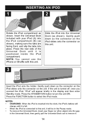
... finger (or other object) into the dock, the iPod's battery will charge until it is full. • When the iPod is turned off, once you connect the iPod, "iPod" will be in the Pause mode. • To remove the Universal Dock, insert your iPod (A) into the iPod compartment (B) (as ...shown), making sure the tabs are facing front, and slip the tabs into the Universal Dock (as shown. NOTES: • CHARGING: When the iPod is positioned inside the iPod compartment. Press the ...
... finger (or other object) into the dock, the iPod's battery will charge until it is full. • When the iPod is turned off, once you connect the iPod, "iPod" will be in the Pause mode. • To remove the Universal Dock, insert your iPod (A) into the iPod compartment (B) (as ...shown), making sure the tabs are facing front, and slip the tabs into the Universal Dock (as shown. NOTES: • CHARGING: When the iPod is positioned inside the iPod compartment. Press the ...

User Guide
Page 15
... ON/OFF switch on the main unit to the ON position. "iPod" will go out. OPERATION USING AN iPod WITH THIS UNIT 1 2 With an iPod connected (see previous page), if this unit is not already on, turn this unit to operate the iPod. 3 4 To play/pause the iPod: Press the PLAY...
... ON/OFF switch on the main unit to the ON position. "iPod" will go out. OPERATION USING AN iPod WITH THIS UNIT 1 2 With an iPod connected (see previous page), if this unit is not already on, turn this unit to operate the iPod. 3 4 To play/pause the iPod: Press the PLAY...

User Guide
Page 17
SYMPTOM No sound from iPod. No image/video on your iPod, set to ON. SOLUTION Increase volume using VOL + / - Check the connection (see page 12). Incorrectly connected. iPod has incorrect settings selected. Unit not connected with the AC cord and/or not turned on . 17 Incorrectly connected. In...iPod can charge only when the unit is set the TV Out setting to minimum. Check the connection (see page 11). iPod not charging. buttons. CAUSE Volume is connected with this unit, check the chart below before calling for service. TROUBLESHOOTING GUIDE If you experience...
SYMPTOM No sound from iPod. No image/video on your iPod, set to ON. SOLUTION Increase volume using VOL + / - Check the connection (see page 12). Incorrectly connected. iPod has incorrect settings selected. Unit not connected with the AC cord and/or not turned on . 17 Incorrectly connected. In...iPod can charge only when the unit is set the TV Out setting to minimum. Check the connection (see page 11). iPod not charging. buttons. CAUSE Volume is connected with this unit, check the chart below before calling for service. TROUBLESHOOTING GUIDE If you experience...

Service Manual
Page 1
MIHTS3202 SERVICE MANUAL Electronic partğ 1ē BOMğ č LIST OF SPARE PART Ď 2ē SchematicğčMAIN aINPUT aVFD / MCU aIPODĎ 3ē ... board 6ē Deal with source and speaker. ēRemote control unavailabilityğ aē Check whether battery install correctly. configuration partğ 1ē Explode view bē Check whether the voltage is connected correctly. cē Whether select a correct mode ( TV or DVD or IPOD ). dē Check whether the system is set minimum adjust it accordingly...
MIHTS3202 SERVICE MANUAL Electronic partğ 1ē BOMğ č LIST OF SPARE PART Ď 2ē SchematicğčMAIN aINPUT aVFD / MCU aIPODĎ 3ē ... board 6ē Deal with source and speaker. ēRemote control unavailabilityğ aē Check whether battery install correctly. configuration partğ 1ē Explode view bē Check whether the voltage is connected correctly. cē Whether select a correct mode ( TV or DVD or IPOD ). dē Check whether the system is set minimum adjust it accordingly...

Service Manual
Page 28
1 2 3 SPEAKER BASS OUT D BASS OUT L OUT CON2 1 2 CON10 1 2 3 4 R OUT C CON9 1 2 3 CON8 MAIN CON12 CON6 CON7 4 CON11 CON1 6 5 4 3 2 1 CON3 3 2 1 6 5 4 3 2 1 5 4 3 2 1 2 1 1 2 5 4 3 2 1 B 5 6 CON401 1 D 2 3 INPUT 4 5 ... 9 8 7 6 5 4 3 2 1 1 2 3 4 5 1 2 1 2 10 11 1 2 3 4 5 3 2 1 1 2 3 4 5 6 7 8 9 TO-CON9 TO-CON8 TO-CON12 A TRANSFORMER 1 2 CON200 VFD 3 CON300 MCU 4 CON1 IPOD A Title TE-2116I connection chart of pcb board Size Number Revision B G.R.Q Date: File: 3-Jun-2008 E ddb Sheet of Drawn By: 5 6
1 2 3 SPEAKER BASS OUT D BASS OUT L OUT CON2 1 2 CON10 1 2 3 4 R OUT C CON9 1 2 3 CON8 MAIN CON12 CON6 CON7 4 CON11 CON1 6 5 4 3 2 1 CON3 3 2 1 6 5 4 3 2 1 5 4 3 2 1 2 1 1 2 5 4 3 2 1 B 5 6 CON401 1 D 2 3 INPUT 4 5 ... 9 8 7 6 5 4 3 2 1 1 2 3 4 5 1 2 1 2 10 11 1 2 3 4 5 3 2 1 1 2 3 4 5 6 7 8 9 TO-CON9 TO-CON8 TO-CON12 A TRANSFORMER 1 2 CON200 VFD 3 CON300 MCU 4 CON1 IPOD A Title TE-2116I connection chart of pcb board Size Number Revision B G.R.Q Date: File: 3-Jun-2008 E ddb Sheet of Drawn By: 5 6

