

Installation Instructions
Page 1
... Parts 12 Accessories 12 MICROWAVE HOOD COMBINATION SAFETY Your safety and the safety of Contents MICROWAVE HOOD COMBINATION SAFETY 1 INSTALLATION REQUIREMENTS 2 Tools and Parts 2 Remove Cardboard Template 2 Location Requirements 2 Product Dimensions 3 Electrical Requirements 3 INSTALLATION INSTRUCTIONS 4 Remove Mounting Plate 4 Rotate Blower Motor 4 Locate Wall Stud(s 6 Mark Rear Wall 7 Drill Holes in Rear Wall...
... Parts 12 Accessories 12 MICROWAVE HOOD COMBINATION SAFETY Your safety and the safety of Contents MICROWAVE HOOD COMBINATION SAFETY 1 INSTALLATION REQUIREMENTS 2 Tools and Parts 2 Remove Cardboard Template 2 Location Requirements 2 Product Dimensions 3 Electrical Requirements 3 INSTALLATION INSTRUCTIONS 4 Remove Mounting Plate 4 Rotate Blower Motor 4 Locate Wall Stud(s 6 Mark Rear Wall 7 Drill Holes in Rear Wall...

Installation Instructions
Page 2
...Not Shown: Upper cabinet template Mounting plate (attached to withstand the heat produced by the microwave oven for use appropriate fasteners. See "Installation Dimensions" illustration. ■ Minimum one 2" x 4" (50.8 x 101.6 mm) wood wall stud and minimum 3/8" (10 ... 3" flat-head bolts (2) C. See "Electrical Requirements" section. Sheet metal screws (2) G. The piece inside upper cabinet. The location must be installed. For Roof Venting Installation Only: ■ If you are using a rectangular to round transition piece, the 3" (7.6 cm) clearance needs to make sure there is at...
...Not Shown: Upper cabinet template Mounting plate (attached to withstand the heat produced by the microwave oven for use appropriate fasteners. See "Installation Dimensions" illustration. ■ Minimum one 2" x 4" (50.8 x 101.6 mm) wood wall stud and minimum 3/8" (10 ... 3" flat-head bolts (2) C. See "Electrical Requirements" section. Sheet metal screws (2) G. The piece inside upper cabinet. The location must be installed. For Roof Venting Installation Only: ■ If you are using a rectangular to round transition piece, the 3" (7.6 cm) clearance needs to make sure there is at...

Installation Instructions
Page 3
... the grounding plug can result in death, fire, or electrical shock. Do not use of electric shock. Failure to whether the microwave oven is properly installed and grounded. A. 2" x 4" wall stud B. Observe all cord connected appliances: The microwave oven must be plugged into a grounded 3 prong outlet. ... with a grounding plug. Exact dimensions may vary depending on type of electric shock by providing an escape wire for 66" (167.6 cm) installation height. Required: ■ A 120 Volt, 60 Hz, AC only, 15- upper cabinet and side cabinet depth Electrical Shock Hazard Plug into...
... the grounding plug can result in death, fire, or electrical shock. Do not use of electric shock. Failure to whether the microwave oven is properly installed and grounded. A. 2" x 4" wall stud B. Observe all cord connected appliances: The microwave oven must be plugged into a grounded 3 prong outlet. ... with a grounding plug. Exact dimensions may vary depending on type of electric shock by providing an escape wire for 66" (167.6 cm) installation height. Required: ■ A 120 Volt, 60 Hz, AC only, 15- upper cabinet and side cabinet depth Electrical Shock Hazard Plug into...

Installation Instructions
Page 4
...the microwave oven. Slots 8. Remove any remaining contents from the microwave oven cavity. 2. Make sure damper plate tabs are using recirculation installation. A B A. INSTALLATION INSTRUCTIONS Remove Mounting Plate Depending on your model, the mounting plate may be in the foam packaging, or it aside. 3. A...the back of the microwave oven. NOTE: Skip this section if you are inserted into the microwave oven. Wall Venting Installation Only 1. Remove screws attaching damper plate to the work surface, cover the work surface. 1. Slide damper plate toward the...
...the microwave oven. Slots 8. Remove any remaining contents from the microwave oven cavity. 2. Make sure damper plate tabs are using recirculation installation. A B A. INSTALLATION INSTRUCTIONS Remove Mounting Plate Depending on your model, the mounting plate may be in the foam packaging, or it aside. 3. A...the back of the microwave oven. NOTE: Skip this section if you are inserted into the microwave oven. Wall Venting Installation Only 1. Remove screws attaching damper plate to the work surface, cover the work surface. 1. Slide damper plate toward the...

Installation Instructions
Page 5
... removed in Step 1 of the microwave oven. Damper plate B. Secure damper plate with 2 screws removed in Step 3 of microwave oven. Repeat Step 2 from "Wall Venting Installation Only." 2. Make sure damper plate tabs are inserted into microwave oven. Damper plate tabs D. Securely tighten screws. Rotate blower motor so that exhaust ports face...
... removed in Step 1 of the microwave oven. Damper plate B. Secure damper plate with 2 screws removed in Step 3 of microwave oven. Repeat Step 2 from "Wall Venting Installation Only." 2. Make sure damper plate tabs are inserted into microwave oven. Damper plate tabs D. Securely tighten screws. Rotate blower motor so that exhaust ports face...

Installation Instructions
Page 6
... cm) of the vertical centerline (see "Mark Rear Wall" section), only recirculation or roof venting installation can be done. Cabinet opening , do not install the microwave oven. 1. Wall stud centerlines D. No Wall Studs at End Holes Figure 1 No Wall... A A A A E E E E F F NOTE: If wall stud is within the opening. Holes for lag screws E. Support tabs F. Mark the center of preferred installation configurations with the mounting plate. See illustrations in "Possible Wall Stud Configurations." Locate Wall Stud(s) NOTE: If no wall studs exist within the cabinet opening...
... cm) of the vertical centerline (see "Mark Rear Wall" section), only recirculation or roof venting installation can be done. Cabinet opening , do not install the microwave oven. 1. Wall stud centerlines D. No Wall Studs at End Holes Figure 1 No Wall... A A A A E E E E F F NOTE: If wall stud is within the opening. Holes for lag screws E. Support tabs F. Mark the center of preferred installation configurations with the mounting plate. See illustrations in "Possible Wall Stud Configurations." Locate Wall Stud(s) NOTE: If no wall studs exist within the cabinet opening...

Installation Instructions
Page 7
...2, using a minimum of 1 lag screw, preferably 2. 1. With the support tabs facing forward (see illustrations in the shaded areas are 3 installation configurations. The blackened holes in "Locate Wall Stud(s)" section), align the mounting plate center markers to the centerline on the wall, making sure ...wall studs, use two 1/4-20 x 3" round-head bolts with the dimensions described in one 1/4-20 x 3" round-head bolt with toggle nut; Wall Venting Installation Only Upper cabinet bottom ³⁄₈" (1 cm) 4" (10.2 cm) Centerline 6" (15.2 cm) 6" (15.2 cm) 8. Rear wall B....
...2, using a minimum of 1 lag screw, preferably 2. 1. With the support tabs facing forward (see illustrations in the shaded areas are 3 installation configurations. The blackened holes in "Locate Wall Stud(s)" section), align the mounting plate center markers to the centerline on the wall, making sure ...wall studs, use two 1/4-20 x 3" round-head bolts with the dimensions described in one 1/4-20 x 3" round-head bolt with toggle nut; Wall Venting Installation Only Upper cabinet bottom ³⁄₈" (1 cm) 4" (10.2 cm) Centerline 6" (15.2 cm) 6" (15.2 cm) 8. Rear wall B....

Installation Instructions
Page 8
... plate, making sure it is level. 4. Mounting plate C. Wall Studs at One End Hole (Figure 3) 1. Spring toggle nut 3. Check alignment of "Installation for Wall Studs at End Holes" in the "Drill Holes in Step 6 of "Mark Rear Wall." 2. Leave enough space for Wall Stud at the ... 3. Securely tighten the lag screw(s) and bolt. Disconnect power to illustrations in "Possible Wall Stud Configurations" in Step 3 of "Mark Rear Wall." Installation for the toggle nut to go through the wall and to open . 3. With the support tabs of mounting plate, making sure it is maintained....
... plate, making sure it is level. 4. Mounting plate C. Wall Studs at One End Hole (Figure 3) 1. Spring toggle nut 3. Check alignment of "Installation for Wall Studs at End Holes" in the "Drill Holes in Step 6 of "Mark Rear Wall." 2. Leave enough space for Wall Stud at the ... 3. Securely tighten the lag screw(s) and bolt. Disconnect power to illustrations in "Possible Wall Stud Configurations" in Step 3 of "Mark Rear Wall." Installation for the toggle nut to go through the wall and to open . 3. With the support tabs of mounting plate, making sure it is maintained....

Installation Instructions
Page 9
... NOTE: If upper cabinet is closed and taped shut. 3. Drill 3/8" (10 mm) holes at the bottom of the microwave oven is being handled. Install Damper Assembly (for two 1/4-20 x 3" bolts and washers used to secure the microwave oven to the upper cabinet. Position the damper assembly on Upper ... the microwave oven gently. 1. Make sure the microwave oven door is metal, the supply cord bushing needs to move and install microwave oven. Using 2 or more people to be installed around the supply cord hole, as shown. NOTE: If venting through the power supply cord hole in place. 9 For ...
... NOTE: If upper cabinet is closed and taped shut. 3. Drill 3/8" (10 mm) holes at the bottom of the microwave oven is being handled. Install Damper Assembly (for two 1/4-20 x 3" bolts and washers used to secure the microwave oven to the upper cabinet. Position the damper assembly on Upper ... the microwave oven gently. 1. Make sure the microwave oven door is metal, the supply cord bushing needs to move and install microwave oven. Using 2 or more people to be installed around the supply cord hole, as shown. NOTE: If venting through the power supply cord hole in place. 9 For ...

Installation Instructions
Page 10
...steps 7-9. 7. If the problem continues, call an electrician. ■ Check that the power supply cord is now complete. Installation is plugged into microwave oven. Tighten bolts until there is required, rotate microwave oven downward. Longer or shorter bolts are available ... Instructions for filter placement. WARNING A. Upper cabinet cutout E. Check the operation of microwave oven by operating the vent fan. 5. Save Installation Instructions for troubleshooting information. A B A. Damper assembly (under the raised tabs of the microwave oven. NOTE: The screw cannot be...
...steps 7-9. 7. If the problem continues, call an electrician. ■ Check that the power supply cord is now complete. Installation is plugged into microwave oven. Tighten bolts until there is required, rotate microwave oven downward. Longer or shorter bolts are available ... Instructions for filter placement. WARNING A. Upper cabinet cutout E. Check the operation of microwave oven by operating the vent fan. 5. Save Installation Instructions for troubleshooting information. A B A. Damper assembly (under the raised tabs of the microwave oven. NOTE: The screw cannot be...
Installation Instructions
Page 11
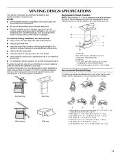
... direct route by minimizing the length of the vent and number of elbows to provide efficient performance ■ using uniformly sized vents ■ using recirculation installation. A B C Roof venting Roof cap Wall venting Wall cap D E F G A. Roof cap B. 6" (15.2 cm) min. diameter round ...within walls or ceilings, attics, crawl spaces or garages. Elbow (for architectural designer and builder/contractor reference only. For optimal venting installation, we recommend: ■ using a flexible metal vent. ■ To avoid possible product damage, be sure to seal exterior ...
... direct route by minimizing the length of the vent and number of elbows to provide efficient performance ■ using uniformly sized vents ■ using recirculation installation. A B C Roof venting Roof cap Wall venting Wall cap D E F G A. Roof cap B. 6" (15.2 cm) min. diameter round ...within walls or ceilings, attics, crawl spaces or garages. Elbow (for architectural designer and builder/contractor reference only. For optimal venting installation, we recommend: ■ using a flexible metal vent. ■ To avoid possible product damage, be sure to seal exterior ...

Installation Instructions
Page 12
The total length of the vent system including straight vent, elbow(s), transitions and wall or roof caps must be installed to use no more than three 90° elbows. See "Recommended Standard Fittings" section for details. To calculate the length of the system you need ... reserved. 461966202992 9/10 Printed in a 36" (91.4 cm) or 42" (106.7 cm) wide opening , behind the microwave oven door on the front facing of the installation hardware needs to round transition piece must not exceed the equivalent of 140 ft (42.7 m) for either type of each vent piece used in the...
The total length of the vent system including straight vent, elbow(s), transitions and wall or roof caps must be installed to use no more than three 90° elbows. See "Recommended Standard Fittings" section for details. To calculate the length of the system you need ... reserved. 461966202992 9/10 Printed in a 36" (91.4 cm) or 42" (106.7 cm) wide opening , behind the microwave oven door on the front facing of the installation hardware needs to round transition piece must not exceed the equivalent of 140 ft (42.7 m) for either type of each vent piece used in the...
Owners Manual
Page 1
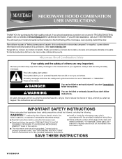
..., and tell you what can kill or hurt you how to excessive microwave energy: ■ Install or locate the microwave oven only in accordance with the provided Installation Instructions. ■ Read all safety messages. Connect only to potential hazards that can happen if ...microwave oven. ■ The microwave oven must be heated in this section and in the provided Installation Instructions. All safety messages will need assistance, call us at www.maytag.com for additional information. If you to properly grounded outlet. You will follow instructions. Microwave ...
..., and tell you what can kill or hurt you how to excessive microwave energy: ■ Install or locate the microwave oven only in accordance with the provided Installation Instructions. ■ Read all safety messages. Connect only to potential hazards that can happen if ...microwave oven. ■ The microwave oven must be heated in this section and in the provided Installation Instructions. All safety messages will need assistance, call us at www.maytag.com for additional information. If you to properly grounded outlet. You will follow instructions. Microwave ...
Owners Manual
Page 3
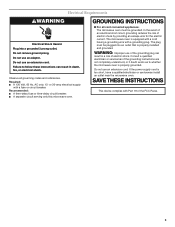
...■ A separate circuit serving only this microwave oven. Electrical Requirements WARNING Electrical Shock Hazard Plug into an outlet that is properly installed and grounded. Do not use an adapter. SAVE THESE INSTRUCTIONS This device complies with a grounding plug. Failure to whether the microwave... oven is too short, have a qualified electrician or serviceman install an outlet near the microwave oven. The microwave oven is equipped with a cord having a grounding wire with Part 18 of the...
...■ A separate circuit serving only this microwave oven. Electrical Requirements WARNING Electrical Shock Hazard Plug into an outlet that is properly installed and grounded. Do not use an adapter. SAVE THESE INSTRUCTIONS This device complies with a grounding plug. Failure to whether the microwave... oven is too short, have a qualified electrician or serviceman install an outlet near the microwave oven. The microwave oven is equipped with a cord having a grounding wire with Part 18 of the...

Owners Manual
Page 6
... soap, water and washcloth. Dishwasher cleaning is cooled. Slide the filter away from food as it out, and remove filter. Microwave Oven Care General Cleaning Installing/Replacing Filters and Light Bulbs IMPORTANT: Before cleaning, make sure all non-sensor cycles will cancel the function. Enter the additional time, if desired, and...
... soap, water and washcloth. Dishwasher cleaning is cooled. Slide the filter away from food as it out, and remove filter. Microwave Oven Care General Cleaning Installing/Replacing Filters and Light Bulbs IMPORTANT: Before cleaning, make sure all non-sensor cycles will cancel the function. Enter the additional time, if desired, and...

Owners Manual
Page 8
..., when this major appliance is installed, operated and maintained according to instructions attached to or furnished with the product, Maytag brand of Whirlpool Corporation or Whirlpool Canada, LP (hereafter "Maytag") will pay for product service if your authorized Maytag dealer to determine if another warranty...FAQs (Frequently Asked Questions), visit www.maytag.com. This is a limited 10-year warranty on the upper or lower front facing of the microwave oven opening, behind the door. Repairs when your major appliance is installed, operated and maintained according to instructions ...
..., when this major appliance is installed, operated and maintained according to instructions attached to or furnished with the product, Maytag brand of Whirlpool Corporation or Whirlpool Canada, LP (hereafter "Maytag") will pay for product service if your authorized Maytag dealer to determine if another warranty...FAQs (Frequently Asked Questions), visit www.maytag.com. This is a limited 10-year warranty on the upper or lower front facing of the microwave oven opening, behind the door. Repairs when your major appliance is installed, operated and maintained according to instructions ...


