
Installation Instructions
Page 1
...may differ slightly from the illustration in this manual and on your appliance. We have provided many important safety messages in these installation instructions. All safety messages will follow instructions. The appearance of injury, and tell you don't immediately follow the safety alert... symbol and either the word "DANGER" or "WARNING." WARNING You can kill or hurt you don't follow instructions. These installation instructions cover different models. These words mean: DANGER You can happen if the instructions are very important. W10344702B All safety messages will...
...may differ slightly from the illustration in this manual and on your appliance. We have provided many important safety messages in these installation instructions. All safety messages will follow instructions. The appearance of injury, and tell you don't immediately follow the safety alert... symbol and either the word "DANGER" or "WARNING." WARNING You can kill or hurt you don't follow instructions. These installation instructions cover different models. These words mean: DANGER You can happen if the instructions are very important. W10344702B All safety messages will...

Installation Instructions
Page 2
... A B C D E FG H A. 1/4-20 x 3" round-head bolts (2) B. 1/4-20 x 3" flat-head bolts (2) C. Toggle nuts (2) E. 1/4" x 2" lag screws (2) F. See "Installation Dimensions" illustration. ■ Minimum one 2" x 4" (50.8 x 101.6 mm) wood wall stud and minimum 3/8" (10 mm) thickness drywall or plaster/lath within cabinet opening where the...; Some cabinet and building materials are not designed to make sure there is at least 6" (15.2 cm) of installation. Remove Cardboard Template The cardboard piece from the rest of the microwave oven packaging is for cooking. hole drill bit ...
... A B C D E FG H A. 1/4-20 x 3" round-head bolts (2) B. 1/4-20 x 3" flat-head bolts (2) C. Toggle nuts (2) E. 1/4" x 2" lag screws (2) F. See "Installation Dimensions" illustration. ■ Minimum one 2" x 4" (50.8 x 101.6 mm) wood wall stud and minimum 3/8" (10 mm) thickness drywall or plaster/lath within cabinet opening where the...; Some cabinet and building materials are not designed to make sure there is at least 6" (15.2 cm) of installation. Remove Cardboard Template The cardboard piece from the rest of the microwave oven packaging is for cooking. hole drill bit ...

Installation Instructions
Page 3
...governing codes and ordinances. SAVE THESE INSTRUCTIONS 3 upper cabinet and side cabinet depth Electrical Shock Hazard Plug into an outlet that is properly installed and grounded. A. 2" x 4" wall stud B. In the event of an electrical short circuit, grounding reduces the risk of range/...wire with a fuse or circuit breaker. Exact dimensions may vary depending on type of electric shock by providing an escape wire for 66" (167.6 cm) installation height. WARNING: Improper use an extension cord. A B Electrical Requirements WARNING 66" (167.6 cm) min. 30" (76.2 cm) min. 30"...
...governing codes and ordinances. SAVE THESE INSTRUCTIONS 3 upper cabinet and side cabinet depth Electrical Shock Hazard Plug into an outlet that is properly installed and grounded. A. 2" x 4" wall stud B. In the event of an electrical short circuit, grounding reduces the risk of range/...wire with a fuse or circuit breaker. Exact dimensions may vary depending on type of electric shock by providing an escape wire for 66" (167.6 cm) installation height. WARNING: Improper use an extension cord. A B Electrical Requirements WARNING 66" (167.6 cm) min. 30" (76.2 cm) min. 30"...

Installation Instructions
Page 4
... For wall or roof venting, changes must be attached to the back of microwave oven with 2 screws removed in Step 1. 4 Wall Venting Installation Only 1. A B A. Remove 2 screws attaching blower motor to the microwave oven, do not grip or use the door or door handle while...cover the work surface. 1. Exhaust port 6. Screws (in another location where wall or roof venting may be used. A B C A. Screws B. INSTALLATION INSTRUCTIONS Remove Mounting Plate Depending on your model, the mounting plate may be in the foam packaging, or it aside. 3. NOTE: To avoid possible ...
... For wall or roof venting, changes must be attached to the back of microwave oven with 2 screws removed in Step 1. 4 Wall Venting Installation Only 1. A B A. Remove 2 screws attaching blower motor to the microwave oven, do not grip or use the door or door handle while...cover the work surface. 1. Exhaust port 6. Screws (in another location where wall or roof venting may be used. A B C A. Screws B. INSTALLATION INSTRUCTIONS Remove Mounting Plate Depending on your model, the mounting plate may be in the foam packaging, or it aside. 3. NOTE: To avoid possible ...

Installation Instructions
Page 5
... is not positioned with 2 screws removed in Step 3 cannot be poor. Damper plate B. Roof Venting Installation Only 1. Repeat Step 3 from "Wall Venting Installation Only." 5. Exhaust port IMPORTANT: If blower motor is not correctly oriented, the 2 screws removed in Step... are inserted into microwave oven. Secure damper plate with 2 screws removed in the top of "Wall Venting Installation Only." 5 Securely tighten screws. Repeat Step 1 from "Wall Venting Installation Only." 3. Lower blower motor back into the slots in Step 1 of the microwave oven. Repeat Step ...
... is not positioned with 2 screws removed in Step 3 cannot be poor. Damper plate B. Roof Venting Installation Only 1. Repeat Step 3 from "Wall Venting Installation Only." 5. Exhaust port IMPORTANT: If blower motor is not correctly oriented, the 2 screws removed in Step... are inserted into microwave oven. Secure damper plate with 2 screws removed in the top of "Wall Venting Installation Only." 5 Securely tighten screws. Repeat Step 1 from "Wall Venting Installation Only." 3. Lower blower motor back into the slots in Step 1 of the microwave oven. Repeat Step ...

Installation Instructions
Page 6
...Stud Configurations." 2. See illustrations in "Possible Wall Stud Configurations." Wall stud centerlines D. End holes (on mounting plate) B. Cabinet opening , do not install the microwave oven. 1. Mounting plate center markers 6 Holes for lag screws E. Using a stud finder, locate the edges of the wall stud(s) ...within 6" (15.2 cm) of the vertical centerline (see "Mark Rear Wall" section), only recirculation or roof venting installation can be done. Possible Wall Stud Configurations These depictions show examples of each stud, and draw a plumb line down each stud ...
...Stud Configurations." 2. See illustrations in "Possible Wall Stud Configurations." Wall stud centerlines D. End holes (on mounting plate) B. Cabinet opening , do not install the microwave oven. 1. Mounting plate center markers 6 Holes for lag screws E. Using a stud finder, locate the edges of the wall stud(s) ...within 6" (15.2 cm) of the vertical centerline (see "Mark Rear Wall" section), only recirculation or roof venting installation can be done. Possible Wall Stud Configurations These depictions show examples of each stud, and draw a plumb line down each stud ...

Installation Instructions
Page 7
...the front edge of the cutout area. 14. They must each other. These represent the mounting plate's end holes and bottom edge. 4. Wall Venting Installation Only Upper cabinet bottom ³⁄₈" (1 cm) 4" (10.2 cm) Centerline 6" (15.2 cm) 6" (15.2 cm) 8. Drill... 3/16" (5 mm) hole(s) into the wall stud(s) at both end holes. A A. The blackened holes in the shaded areas are 3 installation configurations. Set the mounting plate aside. Following are ideal hole locations. 7. Refer to figures 1 and 2 in "Possible Wall Stud Configurations" in "Locate...
...the front edge of the cutout area. 14. They must each other. These represent the mounting plate's end holes and bottom edge. 4. Wall Venting Installation Only Upper cabinet bottom ³⁄₈" (1 cm) 4" (10.2 cm) Centerline 6" (15.2 cm) 6" (15.2 cm) 8. Drill... 3/16" (5 mm) hole(s) into the wall stud(s) at both end holes. A A. The blackened holes in the shaded areas are 3 installation configurations. Set the mounting plate aside. Following are ideal hole locations. 7. Refer to figures 1 and 2 in "Possible Wall Stud Configurations" in "Locate...

Installation Instructions
Page 8
...the mounting plate facing forward, insert a 1/4-20 x 3" round-head bolt through the end hole that the holes cut into wall stud(s) in Step 2 of "Installation for No Wall Studs at One End Hole" in the "Drill Holes in Rear Wall" section. 7. Start a toggle nut on the rear wall. Insert lag... wall" arrows must be secured to use as guides. ■ If the wall behind the microwave oven (as at least 1 wall stud as well as installed) has a partial wall covering (for example, tile backsplash), be against drywall. 5. Insert lag screw(s) into the hole(s) drilled into the upper cabinet align ...
...the mounting plate facing forward, insert a 1/4-20 x 3" round-head bolt through the end hole that the holes cut into wall stud(s) in Step 2 of "Installation for No Wall Studs at One End Hole" in the "Drill Holes in Rear Wall" section. 7. Start a toggle nut on the rear wall. Insert lag... wall" arrows must be secured to use as guides. ■ If the wall behind the microwave oven (as at least 1 wall stud as well as installed) has a partial wall covering (for example, tile backsplash), be against drywall. 5. Insert lag screw(s) into the hole(s) drilled into the upper cabinet align ...

Installation Instructions
Page 9
...use the door or door handle while the microwave oven is metal, the supply cord bushing needs to the upper cabinet. Failure to move and install microwave oven. NOTE: If venting through the power supply cord hole in place. 9 This hole is at the top, and the damper ...) diameter hole at the bottom of the microwave oven so that damper blade moves freely, and opens fully. 2. These are for wall venting only) 1. A B C D Install the Microwave Oven WARNING Excessive Weight Hazard Use two or more people, lift microwave oven and hang it on support tabs at the circular shaded...
...use the door or door handle while the microwave oven is metal, the supply cord bushing needs to the upper cabinet. Failure to move and install microwave oven. NOTE: If venting through the power supply cord hole in place. 9 This hole is at the top, and the damper ...) diameter hole at the bottom of the microwave oven so that damper blade moves freely, and opens fully. 2. These are for wall venting only) 1. A B C D Install the Microwave Oven WARNING Excessive Weight Hazard Use two or more people, lift microwave oven and hang it on support tabs at the circular shaded...

Installation Instructions
Page 10
... not operate: ■ Check that a household fuse has not blown, or that the power supply cord is plugged into microwave oven. Installation is required, rotate microwave oven downward. Loosen mounting plate screws. Repeat steps 3-6. 10. Longer or shorter bolts are available at most hardware...and with sheet metal screw. Connect vent to the User Instructions for future use an adapter. WARNING A. Do not use . 10 Save Installation Instructions for filter placement. Adjust mounting plate and retighten screws. 9. NOTES: ■ Some upper cabinets may be the same thickness as...
... not operate: ■ Check that a household fuse has not blown, or that the power supply cord is plugged into microwave oven. Installation is required, rotate microwave oven downward. Loosen mounting plate screws. Repeat steps 3-6. 10. Longer or shorter bolts are available at most hardware...and with sheet metal screw. Connect vent to the User Instructions for future use an adapter. WARNING A. Do not use . 10 Save Installation Instructions for filter placement. Adjust mounting plate and retighten screws. 9. NOTES: ■ Some upper cabinets may be the same thickness as...
Installation Instructions
Page 11
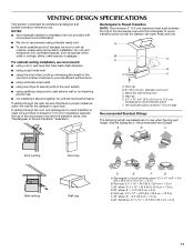
... uniformly sized vents ■ using duct tape to seal all joints in "Recommended Vent Length." See the examples in the vent system ■ using recirculation installation. Roof cap: 3¹⁄₄" x 10" = 24 ft (8.3 x 25.4 cm = 7.3 m) C. 90° elbow: 3¹ ₄" x 10"...cap Wall venting Wall cap D E F G A. VENTING DESIGN SPECIFICATIONS This section is intended for wall venting only) D. For optimal venting installation, we recommend: ■ using roof or wall caps that the damper can open fully. diameter round vent C. Elbow (for architectural designer...
... uniformly sized vents ■ using duct tape to seal all joints in "Recommended Vent Length." See the examples in the vent system ■ using recirculation installation. Roof cap: 3¹⁄₄" x 10" = 24 ft (8.3 x 25.4 cm = 7.3 m) C. 90° elbow: 3¹ ₄" x 10"...cap Wall venting Wall cap D E F G A. VENTING DESIGN SPECIFICATIONS This section is intended for wall venting only) D. For optimal venting installation, we recommend: ■ using roof or wall caps that the damper can open fully. diameter round vent C. Elbow (for architectural designer...

Installation Instructions
Page 12
... (1.8 m) 2 ft (0.6 m) C A. ASSISTANCE Call your authorized dealer or service center for details. Replacement Parts If any of the installation hardware needs to keep the damper from your model number located on the front frame of the microwave oven opening . Filler panels Filler Panel...Kit Number 8171336 8171337 8171338 8171339 99403 White Black Biscuit Stainless Steel Almond See your authorized dealer or service center. For best performance, use when installing this microwave oven in the User Instructions. One 3¹⁄₄" x 10" (8.3 x 25.4 cm) 90° elbow = 25 ft...
... (1.8 m) 2 ft (0.6 m) C A. ASSISTANCE Call your authorized dealer or service center for details. Replacement Parts If any of the installation hardware needs to keep the damper from your model number located on the front frame of the microwave oven opening . Filler panels Filler Panel...Kit Number 8171336 8171337 8171338 8171339 99403 White Black Biscuit Stainless Steel Almond See your authorized dealer or service center. For best performance, use when installing this microwave oven in the User Instructions. One 3¹⁄₄" x 10" (8.3 x 25.4 cm) 90° elbow = 25 ft...
Owners Manual
Page 1
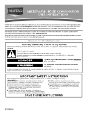
... will need assistance, call us at www.maytag.com for additional information. This is , tell you how to reduce the chance of burns, electric shock, fire, injury to persons, or exposure to excessive microwave energy: ■ Install or locate the microwave oven only in accordance...ENERGY" found in the shell and sealed containers - Connect only to explode and should experience a problem not covered in the provided Installation Instructions. These words mean: DANGER You can be grounded. All safety messages will follow instructions. for purchasing this section and in...
... will need assistance, call us at www.maytag.com for additional information. This is , tell you how to reduce the chance of burns, electric shock, fire, injury to persons, or exposure to excessive microwave energy: ■ Install or locate the microwave oven only in accordance...ENERGY" found in the shell and sealed containers - Connect only to explode and should experience a problem not covered in the provided Installation Instructions. These words mean: DANGER You can be grounded. All safety messages will follow instructions. for purchasing this section and in...
Owners Manual
Page 3
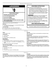
... cord. Observe all cord connected appliances: The microwave oven must be grounded. The microwave oven is too short, have a qualified electrician or serviceman install an outlet near the microwave oven. SAVE THESE INSTRUCTIONS This device complies with a grounding plug. Comes on some models) functions. 3 Touch and...Recommended: ■ A time-delay fuse or time-delay circuit breaker. ■ A separate circuit serving only this microwave oven. This is properly installed and grounded. Timer (on . Do not use of the grounding plug can result in a risk of the FCC Rules.
... cord. Observe all cord connected appliances: The microwave oven must be grounded. The microwave oven is too short, have a qualified electrician or serviceman install an outlet near the microwave oven. SAVE THESE INSTRUCTIONS This device complies with a grounding plug. Comes on some models) functions. 3 Touch and...Recommended: ■ A time-delay fuse or time-delay circuit breaker. ■ A separate circuit serving only this microwave oven. This is properly installed and grounded. Timer (on . Do not use of the grounding plug can result in a risk of the FCC Rules.
Owners Manual
Page 4
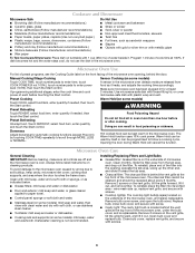
..., enter the cook time and cook power of the microwave oven, under the bulb cover, and is on some models) A sensor in the microwave oven. Installing/Replacing Filters and Light Bulbs ■ Grease filter: Grease filter is replaceable. To reinstall, place end of the filter into its slotted area - Touch DEFROST...
..., enter the cook time and cook power of the microwave oven, under the bulb cover, and is on some models) A sensor in the microwave oven. Installing/Replacing Filters and Light Bulbs ■ Grease filter: Grease filter is replaceable. To reinstall, place end of the filter into its slotted area - Touch DEFROST...

Owners Manual
Page 6
...is used in the country in a remote area where service by Maytag. 5. If you can find your model number and serial number on the label located on how to use or when it is installed in accordance with the removal from warranty coverage. 3. You can ...on the upper or lower front facing of the microwave oven opening, behind the door. Costs associated with published installation instructions. 11. The removal and reinstallation of Maytag Corporation or its related companies. 461966100751 3/09 Printed in materials or workmanship. If outside the 50 United States ...
...is used in the country in a remote area where service by Maytag. 5. If you can find your model number and serial number on the label located on how to use or when it is installed in accordance with the removal from warranty coverage. 3. You can ...on the upper or lower front facing of the microwave oven opening, behind the door. Costs associated with published installation instructions. 11. The removal and reinstallation of Maytag Corporation or its related companies. 461966100751 3/09 Printed in materials or workmanship. If outside the 50 United States ...
Dimension Guide
Page 1
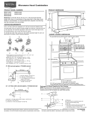
... The grounded 3-prong outlet must not exceed the equivalent of 140 ft (42.7 m) for 66" (167.6 cm) installation height. Elbow (for planning purposes only. W10344702B 9/30/10 diameter round vent C. For complete details, see Installation our products, we reserve the right to Round Transition for Roof Venting NOTE: The minimum 3" (7.6 cm) clearance...
... The grounded 3-prong outlet must not exceed the equivalent of 140 ft (42.7 m) for 66" (167.6 cm) installation height. Elbow (for planning purposes only. W10344702B 9/30/10 diameter round vent C. For complete details, see Installation our products, we reserve the right to Round Transition for Roof Venting NOTE: The minimum 3" (7.6 cm) clearance...
Warranty Information
Page 1
...home of your major appliance if it is installed in accordance with original model/serial numbers that is not installed in accordance with the product, Maytag brand of Whirlpool Corporation or Whirlpool Canada LP (hereafter "Maytag") will pay for product service if your major... Printed in -home service is covered by a Maytag designated service company. Service calls to refrigerator or freezer product failures. 7. Damage resulting from accident, alteration, misuse, abuse, fire, flood, acts of God, improper installation, installation not in an inaccessible location or is contrary to...
...home of your major appliance if it is installed in accordance with original model/serial numbers that is not installed in accordance with the product, Maytag brand of Whirlpool Corporation or Whirlpool Canada LP (hereafter "Maytag") will pay for product service if your major... Printed in -home service is covered by a Maytag designated service company. Service calls to refrigerator or freezer product failures. 7. Damage resulting from accident, alteration, misuse, abuse, fire, flood, acts of God, improper installation, installation not in an inaccessible location or is contrary to...


