Owners Manual
Page 1
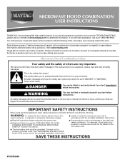
... of burns, electric shock, fire, injury to persons, or exposure to explode and should experience a problem not covered in the provided Installation Instructions. Puede encontrar su número de modelo y de serie en la etiqueta ubicada en la parte frontal de la abertura del ...." MICROWAVE HOOD COMBINATION USER INSTRUCTIONS THANK YOU for example, closed glass jars - All safety messages will need assistance, call us at www.maytag.com for additional information. for purchasing this section and in TROUBLESHOOTING, please visit our website at 1-800-688-9900. If you should not...
... of burns, electric shock, fire, injury to persons, or exposure to explode and should experience a problem not covered in the provided Installation Instructions. Puede encontrar su número de modelo y de serie en la etiqueta ubicada en la parte frontal de la abertura del ...." MICROWAVE HOOD COMBINATION USER INSTRUCTIONS THANK YOU for example, closed glass jars - All safety messages will need assistance, call us at www.maytag.com for additional information. for purchasing this section and in TROUBLESHOOTING, please visit our website at 1-800-688-9900. If you should not...
Owners Manual
Page 3
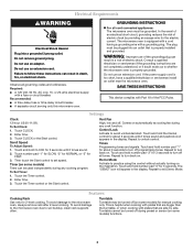
...and padlock icon appears in a risk of the FCC Rules. Repeat to turn back on automatically as to whether the microwave oven is properly installed and grounded. Touch and hold the Cancel control for about 3 seconds to exit Demo Mode. The plug must be turned off (on the...Cooking Rack Use only for FAST. 3. Turntable Turntable may be used independently during any cooking program. This is too short, have a qualified electrician or serviceman install an outlet near the microwave oven. Required: ■ A 120 Volt, 60 Hz, AC only, 15- Touch CLOCK. 2. Then touch the Start ...
...and padlock icon appears in a risk of the FCC Rules. Repeat to turn back on automatically as to whether the microwave oven is properly installed and grounded. Touch and hold the Cancel control for about 3 seconds to exit Demo Mode. The plug must be turned off (on the...Cooking Rack Use only for FAST. 3. Turntable Turntable may be used independently during any cooking program. This is too short, have a qualified electrician or serviceman install an outlet near the microwave oven. Required: ■ A 120 Volt, 60 Hz, AC only, 15- Touch CLOCK. 2. Then touch the Start ...
Owners Manual
Page 4
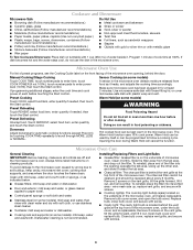
... screws. 4 The Warm Hold function uses 10% cook power. Preset Reheating Touch REHEAT, select food item, enter quantity if needed , then touch the Start control. Installing/Replacing Filters and Light Bulbs ■ Grease filter: Grease filter is not recommended. wire mesh side up the other end, and slide it . Microwave Oven...
... screws. 4 The Warm Hold function uses 10% cook power. Preset Reheating Touch REHEAT, select food item, enter quantity if needed , then touch the Start control. Installing/Replacing Filters and Light Bulbs ■ Grease filter: Grease filter is not recommended. wire mesh side up the other end, and slide it . Microwave Oven...

Owners Manual
Page 6
...Service must be repaired in the home and only in materials or workmanship and is reported to Maytag within 30 days from the date of purchase. 6. Service calls to correct the installation of your major appliance, to instruct you on how to use or when it is used ...correct defects in accordance with original model/serial numbers that is contrary to published user or operator instructions and/or installation instructions. 4. If you may contact Maytag at : Maytag Brand Home Appliances Customer eXperience Center 553 Benson Road Benton Harbor, MI 49022-2692 Please include a daytime phone ...
...Service must be repaired in the home and only in materials or workmanship and is reported to Maytag within 30 days from the date of purchase. 6. Service calls to correct the installation of your major appliance, to instruct you on how to use or when it is used ...correct defects in accordance with original model/serial numbers that is contrary to published user or operator instructions and/or installation instructions. 4. If you may contact Maytag at : Maytag Brand Home Appliances Customer eXperience Center 553 Benson Road Benton Harbor, MI 49022-2692 Please include a daytime phone ...
Installation Instructions
Page 1
...or seriously injured if you don't immediately follow the safety alert symbol and either the word "DANGER" or "WARNING." See "Installation Requirements" section for use above electric or gas cooking products up to potential hazards that can kill or hurt you what the ...potential hazard is, tell you how to Wall 8 Prepare Upper Cabinet 8 Install Damper Assembly 9 Install the Microwave Oven 9 Complete Installation 10 VENTING DESIGN SPECIFICATIONS 11 ASSISTANCE 12 Replacement Parts 12 Accessories 12 MICROWAVE HOOD COMBINATION SAFETY Your safety and the...
...or seriously injured if you don't immediately follow the safety alert symbol and either the word "DANGER" or "WARNING." See "Installation Requirements" section for use above electric or gas cooking products up to potential hazards that can kill or hurt you what the ...potential hazard is, tell you how to Wall 8 Prepare Upper Cabinet 8 Install Damper Assembly 9 Install the Microwave Oven 9 Complete Installation 10 VENTING DESIGN SPECIFICATIONS 11 ASSISTANCE 12 Replacement Parts 12 Accessories 12 MICROWAVE HOOD COMBINATION SAFETY Your safety and the...
Installation Instructions
Page 2
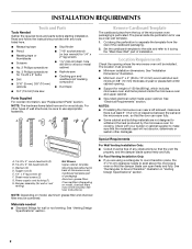
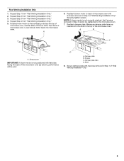
...may not be sure to separate the template from the top of the microwave oven packaging is at least 6" (15.2 cm) of installation. Sheet metal screws (2) G. Power supply cord bushing (1) H. The piece inside upper cabinet. Set the cardboard template to the side and... Duct tape ■ 3/4" (19 mm) hole saw Parts Supplied For reorder information, see "Replacement Parts" section. The location must be installed. See "Venting Design Specifications" section. See "Installation Dimensions" illustration. ■ Minimum one 2" x 4" (50.8 x 101.6 mm) wood wall stud and minimum 3/8" (10 mm) ...
...may not be sure to separate the template from the top of the microwave oven packaging is at least 6" (15.2 cm) of installation. Sheet metal screws (2) G. Power supply cord bushing (1) H. The piece inside upper cabinet. Set the cardboard template to the side and... Duct tape ■ 3/4" (19 mm) hole saw Parts Supplied For reorder information, see "Replacement Parts" section. The location must be installed. See "Venting Design Specifications" section. See "Installation Dimensions" illustration. ■ Minimum one 2" x 4" (50.8 x 101.6 mm) wood wall stud and minimum 3/8" (10 mm) ...
Installation Instructions
Page 3
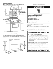
...only this microwave oven. Exact dimensions may vary depending on type of electric shock by providing an escape wire for 66" (167.6 cm) installation height. Product Dimensions 17¹⁄₄" (43.8 cm) 16¹⁄₄" (41.3 cm) (411.06¹c⁄₈m")... (35.6 cm) max. upper cabinet depth Electrical Shock Hazard Plug into an outlet that is properly installed and grounded. The microwave oven is properly grounded. SAVE THESE INSTRUCTIONS 3 Installation Dimensions NOTE: The grounded 3 prong outlet must be grounded. In the event of an electrical short ...
...only this microwave oven. Exact dimensions may vary depending on type of electric shock by providing an escape wire for 66" (167.6 cm) installation height. Product Dimensions 17¹⁄₄" (43.8 cm) 16¹⁄₄" (41.3 cm) (411.06¹c⁄₈m")... (35.6 cm) max. upper cabinet depth Electrical Shock Hazard Plug into an outlet that is properly installed and grounded. The microwave oven is properly grounded. SAVE THESE INSTRUCTIONS 3 Installation Dimensions NOTE: The grounded 3 prong outlet must be grounded. In the event of an electrical short ...
Installation Instructions
Page 4
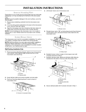
...the microwave oven. A B A. Exhaust port 6. Make sure damper plate tabs are using recirculation installation. A B C A. Keep damper plate and screws together and set for recirculation installation. For wall or roof venting, changes must be made to the back of microwave oven exterior. ... the work surface. 1. Reattach damper plate. Damper plate B. Lift blower motor out of the microwave oven and lift up. Wall Venting Installation Only 1. Damper plate 2. Screws (in Step 1. 4 Damper plate tabs D. Remove any remaining contents from the microwave oven cavity. 2....
...the microwave oven. A B A. Exhaust port 6. Make sure damper plate tabs are using recirculation installation. A B C A. Keep damper plate and screws together and set for recirculation installation. For wall or roof venting, changes must be made to the back of microwave oven exterior. ... the work surface. 1. Reattach damper plate. Damper plate B. Lift blower motor out of the microwave oven and lift up. Wall Venting Installation Only 1. Damper plate 2. Screws (in Step 1. 4 Damper plate tabs D. Remove any remaining contents from the microwave oven cavity. 2....
Installation Instructions
Page 5
... motor to the microwave oven. 7. Make sure damper plate tabs are inserted into microwave oven. A B C A. Screws C. Roof Venting Installation Only 1. Repeat Step 2 from "Wall Venting Installation Only." 5. Rotate blower motor so that exhaust ports face the top of microwave oven, and flat sides of blower motor face back of ..."Wall Venting Installation Only." NOTE: If blower motor is not positioned with flat sides facing the back of the microwave oven (as shown), performance will...
... motor to the microwave oven. 7. Make sure damper plate tabs are inserted into microwave oven. A B C A. Screws C. Roof Venting Installation Only 1. Repeat Step 2 from "Wall Venting Installation Only." 5. Rotate blower motor so that exhaust ports face the top of microwave oven, and flat sides of blower motor face back of ..."Wall Venting Installation Only." NOTE: If blower motor is not positioned with flat sides facing the back of the microwave oven (as shown), performance will...
Installation Instructions
Page 6
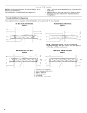
...stud finder, locate the edges of the wall stud(s) within the opening vertical centerline C. Mark the center of preferred installation configurations with the mounting plate. Possible Wall Stud Configurations These depictions show examples of each stud, and draw a ...Hole Figure 3 Wall Studs at End Holes Figure 2 B C C C D B D A A A A E E E E F F NOTE: If wall stud is within the cabinet opening, do not install the microwave oven. 1. No Wall Studs at End Holes Figure 1 No Wall Studs at Both End Holes Figure 4 B D B A A,D A,D A,D E E E E C C C C F F ...
...stud finder, locate the edges of the wall stud(s) within the opening vertical centerline C. Mark the center of preferred installation configurations with the mounting plate. Possible Wall Stud Configurations These depictions show examples of each stud, and draw a ...Hole Figure 3 Wall Studs at End Holes Figure 2 B C C C D B D A A A A E E E E F F NOTE: If wall stud is within the cabinet opening, do not install the microwave oven. 1. No Wall Studs at End Holes Figure 1 No Wall Studs at Both End Holes Figure 4 B D B A A,D A,D A,D E E E E C C C C F F ...
Installation Instructions
Page 7
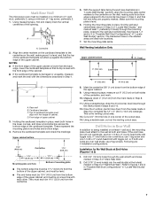
... if 1 end hole is damaged or unusable, measure and mark the wall with the dimensions described in the shaded areas are 3 installation configurations. Following are ideal hole locations. 7. Drill 3/4" (19 mm) holes through the wall at both end holes are over a ..., preferably 2. 1. See figures 1, 2 and/or 3 in "Possible Wall Stud Configurations" in "Locate Wall Stud(s)" section. 7 Set the mounting plate aside. Wall Venting Installation Only Upper cabinet bottom ³⁄₈" (1 cm) 4" (10.2 cm) Centerline 6" (15.2 cm) 6" (15.2 cm) 8. Using measuring tape, measure out ...
... if 1 end hole is damaged or unusable, measure and mark the wall with the dimensions described in the shaded areas are 3 installation configurations. Following are ideal hole locations. 7. Drill 3/4" (19 mm) holes through the wall at both end holes are over a ..., preferably 2. 1. See figures 1, 2 and/or 3 in "Possible Wall Stud Configurations" in "Locate Wall Stud(s)" section. 7 Set the mounting plate aside. Wall Venting Installation Only Upper cabinet bottom ³⁄₈" (1 cm) 4" (10.2 cm) Centerline 6" (15.2 cm) 6" (15.2 cm) 8. Using measuring tape, measure out ...
Installation Instructions
Page 8
..."Locate Wall Stud(s)" section. 3. Securely tighten all contents from the rear wall to points "D" and "E" on at least 1 wall stud as well as installed) has a partial wall covering (for example, tile backsplash), be sure the "Rear Wall" arrows align to the thickest part of the rear wall (for ... bolts. B D A. 1/4-20 x 3" round-head bolt B. Start toggle nuts on the bolt from the back of the mounting plate. Check alignment of "Installation for the toggle nut to go through the wall and to open . 3. Insert lag screw(s) into the hole(s) drilled into the studs at End Holes...
..."Locate Wall Stud(s)" section. 3. Securely tighten all contents from the rear wall to points "D" and "E" on at least 1 wall stud as well as installed) has a partial wall covering (for example, tile backsplash), be sure the "Rear Wall" arrows align to the thickest part of the rear wall (for ... bolts. B D A. 1/4-20 x 3" round-head bolt B. Start toggle nuts on the bolt from the back of the mounting plate. Check alignment of "Installation for the toggle nut to go through the wall and to open . 3. Insert lag screw(s) into the hole(s) drilled into the studs at End Holes...
Installation Instructions
Page 9
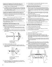
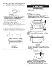
...tilted, thread power supply cord through the wall, make sure the damper assembly fits easily into the vent in back or other injury. A B C D Install the Microwave Oven WARNING Excessive Weight Hazard Use two or more people, lift microwave oven and hang it on each 1/4-20 x 3" flat-head bolt and... place inside upper cabinet near the 3/8" (10 mm) holes. 2. Failure to move and install microwave oven. Place a washer on support tabs at the bottom of the microwave oven so that damper blade moves freely, and opens fully. 2. NOTE: ...
...tilted, thread power supply cord through the wall, make sure the damper assembly fits easily into the vent in back or other injury. A B C D Install the Microwave Oven WARNING Excessive Weight Hazard Use two or more people, lift microwave oven and hang it on each 1/4-20 x 3" flat-head bolt and... place inside upper cabinet near the 3/8" (10 mm) holes. 2. Failure to move and install microwave oven. Place a washer on support tabs at the bottom of the microwave oven so that damper blade moves freely, and opens fully. 2. NOTE: ...
Installation Instructions
Page 10
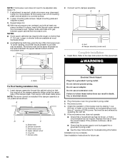
... ■ See the User Instructions for future use. 10 Raised tabs B. Long tab F. Do not use an adapter. Damper assembly C. Installation is plugged into microwave oven. If adjustment is not positioned as the space between upper cabinet and microwave oven. Adjust mounting plate and retighten ...screws. 9. With the microwave oven centered, and with sheet metal screw. To avoid warping, wood filler blocks (installer to follow these instructions can result in place, insert bolts through the cabinet cutout so that a circuit breaker has not tripped. Connect...
... ■ See the User Instructions for future use. 10 Raised tabs B. Long tab F. Do not use an adapter. Damper assembly C. Installation is plugged into microwave oven. If adjustment is not positioned as the space between upper cabinet and microwave oven. Adjust mounting plate and retighten ...screws. 9. With the microwave oven centered, and with sheet metal screw. To avoid warping, wood filler blocks (installer to follow these instructions can result in place, insert bolts through the cabinet cutout so that a circuit breaker has not tripped. Connect...
Installation Instructions
Page 11
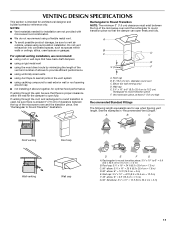
... 7.3 m) C. 90° elbow: 3¹ ₄" x 10" = 25 ft (8.3 x 25.4 cm = 7.6 m) D. 90° elbow: 6" = 10 ft (15.2 cm = 3 m) E. For optimal venting installation, we recommend: ■ using a flexible metal vent. ■ To avoid possible product damage, be sure that there is proper clearance within walls or ceilings, attics...the examples in the vent system ■ using caulking compound to seal exterior wall or roof opening around cap ■ not installing 2 elbows together, for optimal hood performance If venting through the roof, and rectangular to round transition is used, be sure ...
... 7.3 m) C. 90° elbow: 3¹ ₄" x 10" = 25 ft (8.3 x 25.4 cm = 7.6 m) D. 90° elbow: 6" = 10 ft (15.2 cm = 3 m) E. For optimal venting installation, we recommend: ■ using a flexible metal vent. ■ To avoid possible product damage, be sure that there is proper clearance within walls or ceilings, attics...the examples in the vent system ■ using caulking compound to seal exterior wall or roof opening around cap ■ not installing 2 elbows together, for optimal hood performance If venting through the roof, and rectangular to round transition is used, be sure ...
Installation Instructions
Page 12
.... Recommended Vent Length A 3¹⁄₄" x 10" (8.3 x 25.4 cm) rectangular or 6" (15.2 cm) round vent should be installed to keep the damper from your model number located on the front facing of the microwave oven opening . The filler panels come in China Each... the system you call us at our toll free number or visit our website listed in the User Instructions. To calculate the length of the installation hardware needs to round transition piece = 5 ft (1.5 m) D. 2 ft (0.6 m) + 6 ft (1.8 m) straight = 8 ft (2.4 m) If the existing vent is located behind the ...
.... Recommended Vent Length A 3¹⁄₄" x 10" (8.3 x 25.4 cm) rectangular or 6" (15.2 cm) round vent should be installed to keep the damper from your model number located on the front facing of the microwave oven opening . The filler panels come in China Each... the system you call us at our toll free number or visit our website listed in the User Instructions. To calculate the length of the installation hardware needs to round transition piece = 5 ft (1.5 m) D. 2 ft (0.6 m) + 6 ft (1.8 m) straight = 8 ft (2.4 m) If the existing vent is located behind the ...


