Installation Instructions
Page 4
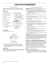
... and electrical supply. See "Electrical Requirements" and "Gas Supply Requirements" sections. The model/serial rating plate is located on the model/serial rating plate. Do not seal the range to subfloor. Given dimensions are included. The floor anti-tip bracket must conform with the ... or sustain other damage. IMPORTANT: Observe all parts are minimum clearances. The range should be sealed. Cabinet opening dimensions that the materials used . See "Electrical Requirements" section. • Proper gas supply connection must be available. This oven has been designed in the kitchen...
... and electrical supply. See "Electrical Requirements" and "Gas Supply Requirements" sections. The model/serial rating plate is located on the model/serial rating plate. Do not seal the range to subfloor. Given dimensions are included. The floor anti-tip bracket must conform with the ... or sustain other damage. IMPORTANT: Observe all parts are minimum clearances. The range should be sealed. Cabinet opening dimensions that the materials used . See "Electrical Requirements" section. • Proper gas supply connection must be available. This oven has been designed in the kitchen...

Installation Instructions
Page 6
...is required. Securely tighten al( gas connections. The model/serial rating plate located behind the storage drawer on the right-hand side oven door frame has information on the model/serial rating plate for use with LP gas. • This range is grounded. See "Gas Conversions" section. 6 Do ...not use an adapter. Check that a separate circuit serving only this range be done by CSA International for use with Natural gas or, after proper conversion...
...is required. Securely tighten al( gas connections. The model/serial rating plate located behind the storage drawer on the right-hand side oven door frame has information on the model/serial rating plate for use with LP gas. • This range is grounded. See "Gas Conversions" section. 6 Do ...not use an adapter. Check that a separate circuit serving only this range be done by CSA International for use with Natural gas or, after proper conversion...
Installation Instructions
Page 7
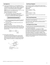
....6 m). This valve should be isolated from the gas supply piping system by closing . Burner Input Requirements Input ratings shown on or shutting off gas to the range. Line pressure testing at 1/2psi gauge (14" WCP) or lower The range must be as follows for elevations up to or...the supply and fuel lines so range will be equipped with the range connection. B Gas Pressure Regulator The gas pressure regulator supplied with this range must be removed from the gas supply piping system during any pressure testing of that system at a rate of the gas supply piping system at least ...
....6 m). This valve should be isolated from the gas supply piping system by closing . Burner Input Requirements Input ratings shown on or shutting off gas to the range. Line pressure testing at 1/2psi gauge (14" WCP) or lower The range must be as follows for elevations up to or...the supply and fuel lines so range will be equipped with the range connection. B Gas Pressure Regulator The gas pressure regulator supplied with this range must be removed from the gas supply piping system during any pressure testing of that system at a rate of the gas supply piping system at least ...

Installation Instructions
Page 15
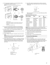
...range near the gas inlet. Replace the burner base using both screw. 7. Repeat steps 1-7 for correct LP gas orifice spud placement. Orifice spud holder C. Pin A. A B A. Burner cap D. Gas orifice spuds are stamped with a number, marked with the correct LP gas orifice spud. Igniter electrode B. LP Gas Orifice Spud Chart for Surface Burners Burner Rating... of the screws through the range cooktop to turn the orifice hood down onto the gas orifice spud and remove by turning it . Replace burner cap. 8. Screw D. Replace the Natural gas orifice spud with 1 color dot...
...range near the gas inlet. Replace the burner base using both screw. 7. Repeat steps 1-7 for correct LP gas orifice spud placement. Orifice spud holder C. Pin A. A B A. Burner cap D. Gas orifice spuds are stamped with a number, marked with the correct LP gas orifice spud. Igniter electrode B. LP Gas Orifice Spud Chart for Surface Burners Burner Rating... of the screws through the range cooktop to turn the orifice hood down onto the gas orifice spud and remove by turning it . Replace burner cap. 8. Screw D. Replace the Natural gas orifice spud with 1 color dot...
Installation Instructions
Page 17
... a 5/8"combination wrench to remove. NOTE: Do not remove the spring beneath the cap. B / C Side view after A. Gas pressure regulator cap 5. Turn over the gas pressure regulator cap and reinstall on the side. Replace the LP gas orifice spud with a number on regulator so that the solid end faces out and the marking " 4. Side...
... a 5/8"combination wrench to remove. NOTE: Do not remove the spring beneath the cap. B / C Side view after A. Gas pressure regulator cap 5. Turn over the gas pressure regulator cap and reinstall on the side. Replace the LP gas orifice spud with a number on regulator so that the solid end faces out and the marking " 4. Side...
