Owners Manual
Page 1
...8 Aluminum Foil 8 Positioning Racks and Bakeware 8 Oven Vent 9 Baking and Roasting 9 Broiling 9 Convection Cooking 9 Timed Cooking 10 RANGE CARE 10 Self-Cleaning Cycle 10 General Cleaning 11 Oven Light 11 TROUBLESHOOTING 12 ACCESSORIES 13 WARRANTY 14 W10239459A Para obtener acceso a "...maytag.com Tenga listo su número de modelo completo. You will need assistance, call us at www.maytag.com for purchasing this high-quality product. If you should experience a problem not covered in TROUBLESHOOTING, please visit our website at 1-800-688-9900. ELECTRIC RANGE...
...8 Aluminum Foil 8 Positioning Racks and Bakeware 8 Oven Vent 9 Baking and Roasting 9 Broiling 9 Convection Cooking 9 Timed Cooking 10 RANGE CARE 10 Self-Cleaning Cycle 10 General Cleaning 11 Oven Light 11 TROUBLESHOOTING 12 ACCESSORIES 13 WARRANTY 14 W10239459A Para obtener acceso a "...maytag.com Tenga listo su número de modelo completo. You will need assistance, call us at www.maytag.com for purchasing this high-quality product. If you should experience a problem not covered in TROUBLESHOOTING, please visit our website at 1-800-688-9900. ELECTRIC RANGE...
Owners Manual
Page 2
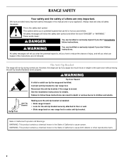
... State of California to cause birth defects or other reproductive harm. 2 All safety messages will follow instructions. The Anti-Tip Bracket The range will tell you what can be killed or seriously injured if you to children and adults. Always read and obey all safety messages....Connect anti-tip bracket to the open door without having the anti-tip bracket fastened down properly. Reconnect the anti-tip bracket, if the range is the safety alert symbol. State of California Proposition 65 Warnings: WARNING: This product contains a chemical known to the State of California ...
... State of California to cause birth defects or other reproductive harm. 2 All safety messages will follow instructions. The Anti-Tip Bracket The range will tell you what can be killed or seriously injured if you to children and adults. Always read and obey all safety messages....Connect anti-tip bracket to the open door without having the anti-tip bracket fastened down properly. Reconnect the anti-tip bracket, if the range is the safety alert symbol. State of California Proposition 65 Warnings: WARNING: This product contains a chemical known to the State of California ...
Owners Manual
Page 3
...9632; DO NOT TOUCH HEATING ELEMENTS OR INTERIOR SURFACES OF OVEN - Only certain types of electric shock, or fire. ■ Glazed Cooking Utensils - Heating elements should be worn while using the range, follow basic precautions, including the following: ■ WARNING: TO REDUCE THE RISK OF ...Not Extend Over Adjacent Surface Units - For self-cleaning ranges - ■ Do Not Clean Door Gasket - Do not repair or replace any part of fire, electrical shock, injury to unintentional contact with the utensil, the handle of electric shock. Flammable materials should be allowed to damage. ...
...9632; DO NOT TOUCH HEATING ELEMENTS OR INTERIOR SURFACES OF OVEN - Only certain types of electric shock, or fire. ■ Glazed Cooking Utensils - Heating elements should be worn while using the range, follow basic precautions, including the following: ■ WARNING: TO REDUCE THE RISK OF ...Not Extend Over Adjacent Surface Units - For self-cleaning ranges - ■ Do Not Clean Door Gasket - Do not repair or replace any part of fire, electrical shock, injury to unintentional contact with the utensil, the handle of electric shock. Flammable materials should be allowed to damage. ...
Owners Manual
Page 4
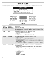
...in hours or minutes up to cancel the Kitchen Timer. Press CLOCK. 3. Press START. 4. Press START. 3. The oven light will sound at www.maytag.com for more than one hour before or after cooking. See "Oven Use" section. 1. The Timer can be set the length of your choice. The...CLEAN OVEN LIGHT CLOCK KITCHEN TIMER ON/OFF FAVORITE FEATURE Self-clean cycle Oven cavity light Clock Oven timer Favorite recipes INSTRUCTIONS See the "Range Care" section. Press any cooking cycle of time. 3. Press KITCHEN TIMER twice to 9 hours and 59 minutes. 1. FEATURE GUIDE This manual covers...
...in hours or minutes up to cancel the Kitchen Timer. Press CLOCK. 3. Press START. 4. Press START. 3. The oven light will sound at www.maytag.com for more than one hour before or after cooking. See "Oven Use" section. 1. The Timer can be set the length of your choice. The...CLEAN OVEN LIGHT CLOCK KITCHEN TIMER ON/OFF FAVORITE FEATURE Self-clean cycle Oven cavity light Clock Oven timer Favorite recipes INSTRUCTIONS See the "Range Care" section. Press any cooking cycle of time. 3. Press KITCHEN TIMER twice to 9 hours and 59 minutes. 1. FEATURE GUIDE This manual covers...
Owners Manual
Page 5
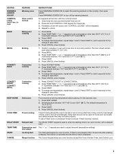
...176;F and 550°F (77°C and 288°C). 3. Delay start should remain open approximately 5" (12.7 cm). 2. If Start is not pressed within 30 seconds after pressing a keypad, the function is canceled and the time of day is 170°F (77°C). 3. Press and hold 3 sec. Press START...except the Clock, Kitchen Timer, and Control Lock. 5 If enabled, a tone will sound, and "CONTROL LOCKED" will function with a delayed start Range function INSTRUCTIONS Press WARMING CENTER ON to select the warming element on at serving temperature before placing it in oven and close door to enter...
...176;F and 550°F (77°C and 288°C). 3. Delay start should remain open approximately 5" (12.7 cm). 2. If Start is not pressed within 30 seconds after pressing a keypad, the function is canceled and the time of day is 170°F (77°C). 3. Press and hold 3 sec. Press START...except the Clock, Kitchen Timer, and Control Lock. 5 If enabled, a tone will sound, and "CONTROL LOCKED" will function with a delayed start Range function INSTRUCTIONS Press WARMING CENTER ON to select the warming element on at serving temperature before placing it in oven and close door to enter...

Owners Manual
Page 6
... heating. When any surface cooking area is in and turn to maintain food quality. Fire Hazard Turn off to keep cooked foods warm. REMEMBER: When range is too hot to touch. 6 The Warming Center element area will glow. Doing so can result in oven more than one hour before and after...
... heating. When any surface cooking area is in and turn to maintain food quality. Fire Hazard Turn off to keep cooked foods warm. REMEMBER: When range is too hot to touch. 6 The Warming Center element area will glow. Doing so can result in oven more than one hour before and after...
Owners Manual
Page 8
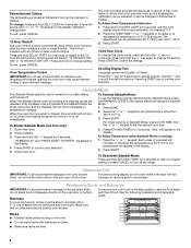
... oven door is opened or closed, the oven light will not turn on or off and the heating elements will appear on or off the range. Press the "+" or "-" keypad to set a temperature other than your previous oven, so the temperature calibration can be changed to confirm the change..., hot air must be able to confirm your selection. Fahrenheit and Celsius The temperature is preset at Fahrenheit, but can be set between 30°F (18°C) and -30°F (-18°C). 3. To change the setting. Repeat to confirm your selection. 5. Scrolling text will appear in the display. To exit...
... oven door is opened or closed, the oven light will not turn on or off and the heating elements will appear on or off the range. Press the "+" or "-" keypad to set a temperature other than your previous oven, so the temperature calibration can be changed to confirm the change..., hot air must be able to confirm your selection. Fahrenheit and Celsius The temperature is preset at Fahrenheit, but can be set between 30°F (18°C) and -30°F (-18°C). 3. To change the setting. Repeat to confirm your selection. 5. Scrolling text will appear in the display. To exit...
Owners Manual
Page 9
... as the actual temperature of meat or poultry, and multiple rack baking. Preheating When START is opened during preheat and bake to maintain a precise temperature range for the oven preheat cycle to wait for optimal cooking results. Convect Roast - Rack 4: Most baked goods on ; It will turn on the display. The...
... as the actual temperature of meat or poultry, and multiple rack baking. Preheating When START is opened during preheat and bake to maintain a precise temperature range for the oven preheat cycle to wait for optimal cooking results. Convect Roast - Rack 4: Most baked goods on ; It will turn on the display. The...
Owners Manual
Page 10
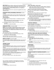
...display will light up . 6. Press the TEMP/TIME "+" or "-" keypads to enter the length of the cycle is time adjustable between 2 hours 30 minutes and 4 hours 30 minutes in 15-minute increments. The cook time oven indicator light will count down . Press TEMP/TIME "+" or "-" keypads to enter a temperature other... the start time. 7. When the set to the correct time of hours and/or minutes you want to move the oven door gasket. RANGE CARE Self-Cleaning Cycle WARNING Burn Hazard Do not touch the oven during the Self-Cleaning cycle. How the Cycle Works IMPORTANT: The heating ...
...display will light up . 6. Press the TEMP/TIME "+" or "-" keypads to enter the length of the cycle is time adjustable between 2 hours 30 minutes and 4 hours 30 minutes in 15-minute increments. The cook time oven indicator light will count down . Press TEMP/TIME "+" or "-" keypads to enter a temperature other... the start time. 7. When the set to the correct time of hours and/or minutes you want to move the oven door gasket. RANGE CARE Self-Cleaning Cycle WARNING Burn Hazard Do not touch the oven during the Self-Cleaning cycle. How the Cycle Works IMPORTANT: The heating ...
Owners Manual
Page 11
...: EXTERIOR PORCELAIN ENAMEL SURFACES (on some models) Food spills containing acids, such as vinegar and tomato, should be ordered as the entire range is recommended regularly to condition the cooktop. To avoid damage, do not remove seals under knobs. When replacing knobs, make sure knobs are... is still warm. Replace bulb, then bulb cover by turning clockwise. 5. Store razor blades out of the reach of our website at www.maytag.com. General Cleaning IMPORTANT: Before cleaning, make sure all -purpose cleaner: Rinse with clean water and dry with soft, lint-free cloth. ...
...: EXTERIOR PORCELAIN ENAMEL SURFACES (on some models) Food spills containing acids, such as vinegar and tomato, should be ordered as the entire range is recommended regularly to condition the cooktop. To avoid damage, do not remove seals under knobs. When replacing knobs, make sure knobs are... is still warm. Replace bulb, then bulb cover by turning clockwise. 5. Store razor blades out of the reach of our website at www.maytag.com. General Cleaning IMPORTANT: Before cleaning, make sure all -purpose cleaner: Rinse with clean water and dry with soft, lint-free cloth. ...
Owners Manual
Page 12
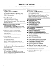
www.maytag.com Nothing will not operate during a self-clean cycle. On some ...Cookware should not extend more than ½" (1.3 cm) outside the cooking area. See "Cooktop Use" section. ■ Is the range level? See "Oven Temperature Control" section of the "Electronic Oven Controls" section. ■ Was the oven preheated? See "Control ..."Electronic Oven Controls" section. Close the oven door all the way. ■ Has the function been entered? Level the range. See "Positioning Racks and Bakeware" section. ■ Is there proper air circulation around cookware on the bottom? See ...
www.maytag.com Nothing will not operate during a self-clean cycle. On some ...Cookware should not extend more than ½" (1.3 cm) outside the cooking area. See "Cooktop Use" section. ■ Is the range level? See "Oven Temperature Control" section of the "Electronic Oven Controls" section. ■ Was the oven preheated? See "Control ..."Electronic Oven Controls" section. Close the oven door all the way. ■ Has the function been entered? Level the range. See "Positioning Racks and Bakeware" section. ■ Is there proper air circulation around cookware on the bottom? See ...
Installation Instructions
Page 1
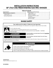
.... IMPORTANT: Save for local electrical inspector's use. INSTALLATION INSTRUCTIONS 30" (76.0 CM) FREESTANDING ELECTRIC RANGES Table of Contents RANGE SAFETY 1 INSTALLATION REQUIREMENTS 2 Tools and Parts 2 Location Requirements 2 Electrical Requirements 3 INSTALLATION INSTRUCTIONS 4 Unpack Range 4 Install Anti-Tip Bracket 5 Electrical Connection 6 Verify Anti-Tip Bracket Location 11 Level Range 11 Complete Installation 11 Moving the Range 12 RANGE SAFETY Your safety and the...
.... IMPORTANT: Save for local electrical inspector's use. INSTALLATION INSTRUCTIONS 30" (76.0 CM) FREESTANDING ELECTRIC RANGES Table of Contents RANGE SAFETY 1 INSTALLATION REQUIREMENTS 2 Tools and Parts 2 Location Requirements 2 Electrical Requirements 3 INSTALLATION INSTRUCTIONS 4 Unpack Range 4 Install Anti-Tip Bracket 5 Electrical Connection 6 Verify Anti-Tip Bracket Location 11 Level Range 11 Complete Installation 11 Moving the Range 12 RANGE SAFETY Your safety and the...
Installation Instructions
Page 2
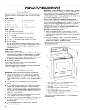
...governing codes and ordinances. ■ It is to comply with upturned ends. See "Electrical Requirements" section. The model/serial rating plate is recommended that are available from your cabinets, check with ranges. A. 28¹⁄₂" (72.4 cm) to backguard standoffs F. Read ...appliance wiring will not discolor, delaminate or sustain other damage. Thickness of this range is adequate as long as it must be reduced by adjusting the leveling legs. ■ Grounded electrical supply is not applicable, the Standard for Mobile Home Construction and Safety, ...
...governing codes and ordinances. ■ It is to comply with upturned ends. See "Electrical Requirements" section. The model/serial rating plate is recommended that are available from your cabinets, check with ranges. A. 28¹⁄₂" (72.4 cm) to backguard standoffs F. Read ...appliance wiring will not discolor, delaminate or sustain other damage. Thickness of this range is adequate as long as it must be reduced by adjusting the leveling legs. ■ Grounded electrical supply is not applicable, the Standard for Mobile Home Construction and Safety, ...
Installation Instructions
Page 3
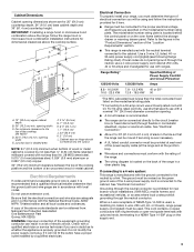
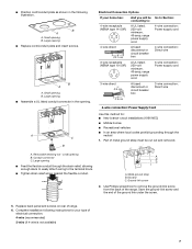
...not less than No. 28 MSG sheet steel, 0.015" (0.4 mm) stainless steel, 0.024" (0.6 mm) aluminum or 0.020" (0.5 mm) copper. 30" (76.2 cm) minimum clearance between the top of the cooking platform and the bottom of slack in a clear plastic bag. or 50-amp power ...36" (91.4 cm) countertop height. For 50-amp rated cord kits, use with the National Electrical Code, ANSI/ NFPA 70-latest edition and all local codes and ordinances. Electrical Connection To properly install your range, you will not fit the outlet, have a proper outlet installed by a qualified electrician. Use...
...not less than No. 28 MSG sheet steel, 0.015" (0.4 mm) stainless steel, 0.024" (0.6 mm) aluminum or 0.020" (0.5 mm) copper. 30" (76.2 cm) minimum clearance between the top of the cooking platform and the bottom of slack in a clear plastic bag. or 50-amp power ...36" (91.4 cm) countertop height. For 50-amp rated cord kits, use with the National Electrical Code, ANSI/ NFPA 70-latest edition and all local codes and ordinances. Electrical Connection To properly install your range, you will not fit the outlet, have a proper outlet installed by a qualified electrician. Use...
Installation Instructions
Page 4
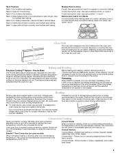
...50P plug on the appliance end must be identified by a green or green/yellow cover and the neutral conductor by a white cover. If a range height adjustment is necessary, use of NEMA Type 10-50R. 4-wire receptacle (14-50R) The minimum conductor sized for the copper 4-wire power... cord are: 40-amp circuit 2 No.-8 conductors 1 No.-10 white neutral 1 No.-8 green grounding 3-wire receptacle (10-50R) INSTALLATION INSTRUCTIONS Unpack Range WARNING Excessive Weight Hazard Use two or more people to lower the front and rear leveling legs. AB C A. Failure to lower front leveling legs. Do...
...50P plug on the appliance end must be identified by a green or green/yellow cover and the neutral conductor by a white cover. If a range height adjustment is necessary, use of NEMA Type 10-50R. 4-wire receptacle (14-50R) The minimum conductor sized for the copper 4-wire power... cord are: 40-amp circuit 2 No.-8 conductors 1 No.-10 white neutral 1 No.-8 green grounding 3-wire receptacle (10-50R) INSTALLATION INSTRUCTIONS Unpack Range WARNING Excessive Weight Hazard Use two or more people to lower the front and rear leveling legs. AB C A. Failure to lower front leveling legs. Do...

Installation Instructions
Page 5
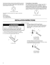
... #12 x 1⁵⁄₈" screws B. A. Anti-tip bracket B. Connect anti-tip bracket to children and adults. 1. Determine and mark the edge of range. Drill two ¹⁄₈" (3.0 mm) holes that right (or left side or right side of the cutout. C 14.5 mm) 4. Determine which ... in the cutout space. Anti-tip bracket A B B C A. #12 x 1⁵⁄₈" screws B. Anti-tip bracket 5. Mark edge of the range in the storage drawer. 2. If you have a stone or masonry floor you can use : floor or wall. Install Anti-Tip Bracket WARNING Floor Mounting A...
... #12 x 1⁵⁄₈" screws B. A. Anti-tip bracket B. Connect anti-tip bracket to children and adults. 1. Determine and mark the edge of range. Drill two ¹⁄₈" (3.0 mm) holes that right (or left side or right side of the cutout. C 14.5 mm) 4. Determine which ... in the cutout space. Anti-tip bracket A B B C A. #12 x 1⁵⁄₈" screws B. Anti-tip bracket 5. Mark edge of the range in the storage drawer. 2. If you have a stone or masonry floor you can use : floor or wall. Install Anti-Tip Bracket WARNING Floor Mounting A...
Installation Instructions
Page 6
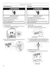
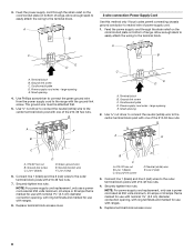
... supply cord. Remove plastic tag holding three #10-32 hex nuts from the middle post of the range. 4. A B A. UL listed strain relief - Add strain relief. Power Supply Cord Electrical Connection Direct Wire WARNING WARNING Electrical Shock Hazard Disconnect power before servicing. Use a new 40 amp power supply cord. Plug into a ...strain relief ■ Assemble a UL listed strain relief in the opening B. Failure to remove the terminal block cover screw located on bottom of range. A B A. Electrically ground range. large opening . 3. Small opening 6
... supply cord. Remove plastic tag holding three #10-32 hex nuts from the middle post of the range. 4. A B A. UL listed strain relief - Add strain relief. Power Supply Cord Electrical Connection Direct Wire WARNING WARNING Electrical Shock Hazard Disconnect power before servicing. Use a new 40 amp power supply cord. Plug into a ...strain relief ■ Assemble a UL listed strain relief in the opening B. Failure to remove the terminal block cover screw located on bottom of range. A B A. Electrically ground range. large opening . 3. Small opening 6
Installation Instructions
Page 7
... - Complete installation following illustration. Large opening B. Conduit connector C. A B C A. Save the ground-link screw and the end of range. 6. Part of metal ground strap must be Go to Section: connecting to the terminal block. ■ Tighten strain relief screw against ...the flexible conduit. small opening ■ Replace cord/conduit plate and insert screws. A C B Electrical Connection Options If your type of the range. Metal ground strap B. Ground-link screw 2. Replace back panel and screws on rear of the ground link under the...
... - Complete installation following illustration. Large opening B. Conduit connector C. A B C A. Save the ground-link screw and the end of range. 6. Part of metal ground strap must be Go to Section: connecting to the terminal block. ■ Tighten strain relief screw against ...the flexible conduit. small opening ■ Replace cord/conduit plate and insert screws. A C B Electrical Connection Options If your type of the range. Metal ground strap B. Ground-link screw 2. Replace back panel and screws on rear of the ground link under the...
Installation Instructions
Page 8
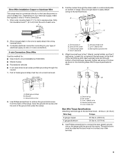
...wire E. Replace terminal block access cover. 8 Feed the power supply cord through the strain relief on the cord/conduit plate on bottom of range. A C B E D A. Ground-link screw C. large opening 4. Use ³⁄₈" nut driver to connect the neutral (... terminal block. Terminal block B. Terminal block B. Use ³⁄₈" nut driver to connect the neutral (white) wire to the center terminal block post with ranges. 8. Line 1 (black) C. 3. large opening 2. Green ground wire E. Ground-link screw D. A F A E B C E A. #10-32 hex nut B. Line...
...wire E. Replace terminal block access cover. 8 Feed the power supply cord through the strain relief on the cord/conduit plate on bottom of range. A C B E D A. Ground-link screw C. large opening 4. Use ³⁄₈" nut driver to connect the neutral (... terminal block. Terminal block B. Terminal block B. Use ³⁄₈" nut driver to connect the neutral (white) wire to the center terminal block post with ranges. 8. Line 1 (black) C. 3. large opening 2. Green ground wire E. Ground-link screw D. A F A E B C E A. #10-32 hex nut B. Line...
Installation Instructions
Page 9
...) wire F. Securely tighten set screw on the front of the terminal lug and insert exposed wire end through bottom of the range. Discard C. Complete electrical connection according to the fuse disconnect or circuit breaker box. Allow enough slack to easily attach wiring to line 1 (black),... C 3. Pull the conduit through the neutral 1. Loosen (do not remove) the set screw to remove the ground-link screw from the end of electrical supply (4-wire or 3-wire connection). 4-wire Connection: Direct Wire Use this method for: ■ New branch-circuit installations (1996 NEC) ■ ...
...) wire F. Securely tighten set screw on the front of the terminal lug and insert exposed wire end through bottom of the range. Discard C. Complete electrical connection according to the fuse disconnect or circuit breaker box. Allow enough slack to easily attach wiring to line 1 (black),... C 3. Pull the conduit through the neutral 1. Loosen (do not remove) the set screw to remove the ground-link screw from the end of electrical supply (4-wire or 3-wire connection). 4-wire Connection: Direct Wire Use this method for: ■ New branch-circuit installations (1996 NEC) ■ ...


