
Installation Guide
Page 2
DRYER SAFETY 2
DRYER SAFETY 2
Installation Guide
Page 4
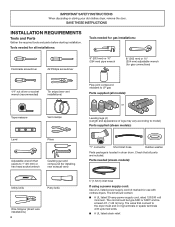
...Tape measure Vent clamps Level Pliers Adjustable wrench that all models): or Leveling legs (4) (Length and appearance of legs may vary according to the dryer must end in dryer drum. The cord should contain: ■■ A UL listed 30-amp power supply cord, rated 120/240 volt minimum. The kit should ...to model) Parts supplied (steam models): "Y" connector Short inlet hose Rubber washer Parts package is located in ring terminals or spade terminals with clothes dryers. INSTALLATION REQUIREMENTS Tools and Parts Gather the required tools and parts before starting installation.
...Tape measure Vent clamps Level Pliers Adjustable wrench that all models): or Leveling legs (4) (Length and appearance of legs may vary according to the dryer must end in dryer drum. The cord should contain: ■■ A UL listed 30-amp power supply cord, rated 120/240 volt minimum. The kit should ...to model) Parts supplied (steam models): "Y" connector Short inlet hose Rubber washer Parts package is located in ring terminals or spade terminals with clothes dryers. INSTALLATION REQUIREMENTS Tools and Parts Gather the required tools and parts before starting installation.
Installation Guide
Page 5
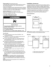
...717 mm) A B A. Wide opening hamper door 5 For further information, please refer to shut off at end of 1" (25 mm) under entire dryer. Dryer Dimensions Front View 29" (737 mm) 407/8" (1038 mm) You will be considered. ■■ Level floor with maximum slope of automatic sensor ...the water fill valves, and water pressure of the accompanying washer. Parts needed for your dryer. Add spacing on all sides of dryer to support dryer and a total weight (dryer and load) of dryer. If not level, clothes may not tumble properly and automatic sensor cycles may use the ...
...717 mm) A B A. Wide opening hamper door 5 For further information, please refer to shut off at end of 1" (25 mm) under entire dryer. Dryer Dimensions Front View 29" (737 mm) 407/8" (1038 mm) You will be considered. ■■ Level floor with maximum slope of automatic sensor ...the water fill valves, and water pressure of the accompanying washer. Parts needed for your dryer. Add spacing on all sides of dryer to support dryer and a total weight (dryer and load) of dryer. If not level, clothes may not tumble properly and automatic sensor cycles may use the ...
Installation Guide
Page 6
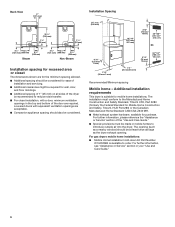
... spacing should also be considered. Louvered doors with a door, minimum ventilation openings in your "Use and Care Guide." 6 For gas dryers mobile home installations: ■■ Mobile Home Installation Hold-down Kit Part Number W10432680 is suitable for mobile home installations. For further ... wall, door, and floor moldings. ■■ Additional spacing of 1" (25 mm) on all sides of the dryer is recommended to reduce noise transfer. ■■ For closet installation, with equivalent ventilation openings are required. Additional installation requirements This...
... spacing should also be considered. Louvered doors with a door, minimum ventilation openings in your "Use and Care Guide." 6 For gas dryers mobile home installations: ■■ Mobile Home Installation Hold-down Kit Part Number W10432680 is suitable for mobile home installations. For further ... wall, door, and floor moldings. ■■ Additional spacing of 1" (25 mm) on all sides of the dryer is recommended to reduce noise transfer. ■■ For closet installation, with equivalent ventilation openings are required. Additional installation requirements This...
Installation Guide
Page 7
...wire, see "Optional 3-wire connection" section. ■■ A 4-wire power supply connection must be used , it here. ■■ This dryer is adequate. When the neutral ground conductor is isolated from : National Fire Protection Association, One Batterymarch Park, Quincy, MA 02269. ■■ To... cord with flexible metallic conduit. The 4-wire power supply cord, at least 4 ft. (1.22 m) long, must end in conformance with clothes dryers. The neutral conductor must match power supply (4-wire or 3-wire) and be insulated. ■■ 10-gauge solid copper wire (do not ...
...wire, see "Optional 3-wire connection" section. ■■ A 4-wire power supply connection must be used , it here. ■■ This dryer is adequate. When the neutral ground conductor is isolated from : National Fire Protection Association, One Batterymarch Park, Quincy, MA 02269. ■■ To... cord with flexible metallic conduit. The 4-wire power supply cord, at least 4 ft. (1.22 m) long, must end in conformance with clothes dryers. The neutral conductor must match power supply (4-wire or 3-wire) and be insulated. ■■ 10-gauge solid copper wire (do not ...
Installation Guide
Page 8
...is equipped with a CSA International Certified Power Cord intended to be plugged into an appropriate outlet that a separate circuit serving only this dryer be provided. 8 In the event of malfunction or breakdown, grounding will not t the outlet, have a proper outlet installed by... providing a path of least resistance for electric current. This dryer is properly installed and grounded in "Assistance or Service" section of your responsibility: ■■ To contact a qualified electrical installer. &#...
...is equipped with a CSA International Certified Power Cord intended to be plugged into an appropriate outlet that a separate circuit serving only this dryer be provided. 8 In the event of malfunction or breakdown, grounding will not t the outlet, have a proper outlet installed by... providing a path of least resistance for electric current. This dryer is properly installed and grounded in "Assistance or Service" section of your responsibility: ■■ To contact a qualified electrical installer. &#...
Installation Guide
Page 9
... "Assistance or Service" section of the equipment- Do not use LP gas, 3/8" LP compatible copper tubing can result in a risk of the dryer. It is designcertified by a quali ed electrician. GAS SUPPLY LINE Option 1 (Recommended Method) Flexible stainless steel gas connector: ■■ If... local codes permit, use with the National Fuel Gas Code, ANSI Z223.1. GROUNDING INSTRUCTIONS I For a grounded, cord-connected dryer: This dryer must be plugged into an appropriate outlet that is properly installed and grounded in accordance with all local codes and ordinances. The plug ...
... "Assistance or Service" section of the equipment- Do not use LP gas, 3/8" LP compatible copper tubing can result in a risk of the dryer. It is designcertified by a quali ed electrician. GAS SUPPLY LINE Option 1 (Recommended Method) Flexible stainless steel gas connector: ■■ If... local codes permit, use with the National Fuel Gas Code, ANSI Z223.1. GROUNDING INSTRUCTIONS I For a grounded, cord-connected dryer: This dryer must be plugged into an appropriate outlet that is properly installed and grounded in accordance with all local codes and ordinances. The plug ...

Installation Guide
Page 10
...tapping D. 1/2" NPT gas supply line E. Gas supply pressure testing ■ The dryer must be disconnected from dryer carton; Slide the dryer until it is required for each 1,000 ft. (305 m) increase in leveling legs Dryer gas pipe or ■ The gas pipe that comes out through the rear ... wrench and tape measure, screw leveling legs into leg holes until bottom of foot is approximately 1/2" (13 mm) from bottom of dryer (so that the dryer height matches that complies with the standard for connectors for leveling legs GAS SUPPLY CONNECTION REQUIREMENTS ■ Use an elbow and a 3/8"...
...tapping D. 1/2" NPT gas supply line E. Gas supply pressure testing ■ The dryer must be disconnected from dryer carton; Slide the dryer until it is required for each 1,000 ft. (305 m) increase in leveling legs Dryer gas pipe or ■ The gas pipe that comes out through the rear ... wrench and tape measure, screw leveling legs into leg holes until bottom of foot is approximately 1/2" (13 mm) from bottom of dryer (so that the dryer height matches that complies with the standard for connectors for leveling legs GAS SUPPLY CONNECTION REQUIREMENTS ■ Use an elbow and a 3/8"...
Installation Guide
Page 12
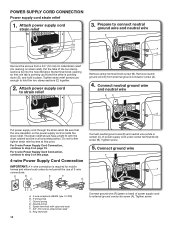
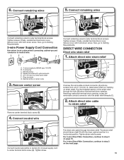
... of the two clamp sections (C) into the hole (B) below the terminal block opening so that the wire insulation on page 13. B. C. Spade terminals with the dryer cabinet and be in place. Put the tabs of 3-wire connections. Attach power supply cord to external ground conductor screw (A). Neutral prong E. Ring terminals 12...
... of the two clamp sections (C) into the hole (B) below the terminal block opening so that the wire insulation on page 13. B. C. Spade terminals with the dryer cabinet and be in place. Put the tabs of 3-wire connections. Attach power supply cord to external ground conductor screw (A). Neutral prong E. Ring terminals 12...
Installation Guide
Page 13
... to outer terminal block screws. DIRECT WIRE CONNECTION Direct wire strain relief 1. Neutral prong D. Tighten screw. Now, go to neutral wire. C. Spade terminals with the dryer cabinet and be in a horizontal position. The strain relief should have a tight fit with upturned ends E. 3/4" (19 mm) UL listed strain relief F. For 4-wire Direct...
... to outer terminal block screws. DIRECT WIRE CONNECTION Direct wire strain relief 1. Neutral prong D. Tighten screw. Now, go to neutral wire. C. Spade terminals with the dryer cabinet and be in a horizontal position. The strain relief should have a tight fit with upturned ends E. 3/4" (19 mm) UL listed strain relief F. For 4-wire Direct...
Installation Guide
Page 14
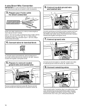
... is required for direct connection EC 31 (89 ⁄2" mm) (251"mm) B (127 5" mm) Direct wire cable must have 5 ft. (1.52 m) of extra length so dryer may be moved if needed. Connect neutral ground wire and neutral wire 3.
... is required for direct connection EC 31 (89 ⁄2" mm) (251"mm) B (127 5" mm) Direct wire cable must have 5 ft. (1.52 m) of extra length so dryer may be moved if needed. Connect neutral ground wire and neutral wire 3.
Installation Guide
Page 15
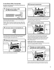
... ends together and tighten screws. Prepare to Venting Requirements. Shape wire ends into slot of extra length so dryer may be moved if needed. Optional 3-wire Connection You must have 5 ft. (1.52 m) of dryer rear panel. Connect remaining wires To connect wires to neutral wire. 6. Now, go to connect neutral ground wire...
... ends together and tighten screws. Prepare to Venting Requirements. Shape wire ends into slot of extra length so dryer may be moved if needed. Optional 3-wire Connection You must have 5 ft. (1.52 m) of dryer rear panel. Connect remaining wires To connect wires to neutral wire. 6. Now, go to connect neutral ground wire...
Installation Guide
Page 16
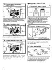
.... Bubbles will show a leak. Using a wrench to tighten, connect gas supply to Venting Requirements. Tighten screws. 4. Now, go to dryer. Correct any leaks found. 16 Tighten screw. 3. Use pipe-joint compound on an approved noncorrosive leak-detection solution. valve is open when ...handle is parallel to dryer Flared B maAle fitting mNoalne-fflBiattriendg Connect neutral ground wire (E) and neutral wire (white or center wire) (C) of LP gas. ...
.... Bubbles will show a leak. Using a wrench to tighten, connect gas supply to Venting Requirements. Tighten screws. 4. Now, go to dryer. Correct any leaks found. 16 Tighten screw. 3. Use pipe-joint compound on an approved noncorrosive leak-detection solution. valve is open when ...handle is parallel to dryer Flared B maAle fitting mNoalne-fflBiattriendg Connect neutral ground wire (E) and neutral wire (white or center wire) (C) of LP gas. ...
Installation Guide
Page 17
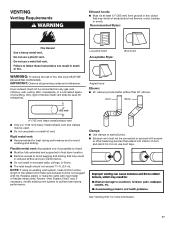
... space of a building. IMPORTANT: Observe all joints. ■■ Exhaust vent must not be connected into interior of duct and catch lint. Dryer exhaust must not be connected or secured with screws or other fastening devices that extend into any object that may result in reduced airflow and... not use plastic or metal foil vent. Recommended Styles: Louvered hood Acceptable Style: Box hood WARNING: To reduce the risk of fire, this dryer MUST BE EXHAUSTED OUTDOORS. VENTING Venting Requirements Exhaust hoods: ■■ Must be at least 12" (305 mm) from entire length of ...
... space of a building. IMPORTANT: Observe all joints. ■■ Exhaust vent must not be connected into interior of duct and catch lint. Dryer exhaust must not be connected or secured with screws or other fastening devices that extend into any object that may result in reduced airflow and... not use plastic or metal foil vent. Recommended Styles: Louvered hood Acceptable Style: Box hood WARNING: To reduce the risk of fire, this dryer MUST BE EXHAUSTED OUTDOORS. VENTING Venting Requirements Exhaust hoods: ■■ Must be at least 12" (305 mm) from entire length of ...
Installation Guide
Page 18
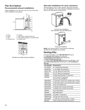
... possible. Elbow C. Venting Kits For more information, call 1-800-688-2002 (Whirlpool and Maytag) or visit us at www.whirlpoolparts.ca (Whirlpool) or www.maytag.ca (Maytag). B C D A E F G B E H A. Exhaust hood E. Two close elbow 4396007RW Through-the-wall vent cap 4396008RP 4" steel dryer venting clamps - 2 pack 8212662 Flush mounting louvered vent hood 4" Refer to connect elbows...
... possible. Elbow C. Venting Kits For more information, call 1-800-688-2002 (Whirlpool and Maytag) or visit us at www.whirlpoolparts.ca (Whirlpool) or www.maytag.ca (Maytag). B C D A E F G B E H A. Exhaust hood E. Two close elbow 4396007RW Through-the-wall vent cap 4396008RP 4" steel dryer venting clamps - 2 pack 8212662 Flush mounting louvered vent hood 4" Refer to connect elbows...
Installation Guide
Page 19
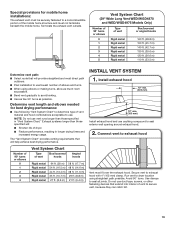
...and must fit over the exhaust hood. Terminate the exhaust vent outside. Exhaust systems longer than those specified will: ■ Shorten life of dryer. ■ Reduce performance, resulting in "Vent System Chart." The "Vent System Chart" provides venting requirements that will help achieve best drying ...(17.7 m) 48 ft. (14.6 m) 38 ft. (11.6 m) 29 ft. (8.8 m) 21 ft. (6.4 m) Vent must not terminate beneath the mobile home. Run vent to dryer location using elbows or making turns, allow as much room as possible. ■ Bend vent gradually to avoid kinking. ■ Use as few 90°...
...and must fit over the exhaust hood. Terminate the exhaust vent outside. Exhaust systems longer than those specified will: ■ Shorten life of dryer. ■ Reduce performance, resulting in "Vent System Chart." The "Vent System Chart" provides venting requirements that will help achieve best drying ...(17.7 m) 48 ft. (14.6 m) 38 ft. (11.6 m) 29 ft. (8.8 m) 21 ft. (6.4 m) Vent must not terminate beneath the mobile home. Run vent to dryer location using elbows or making turns, allow as much room as possible. ■ Bend vent gradually to avoid kinking. ■ Use as few 90°...
Installation Guide
Page 20
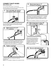
... it is turned on cold water faucet Using pliers, tighten the couplings with new rubber washer. 2. NOTE: Do not overtighten. Attach long hose to dryer fill valve and tighten coupling 301/4" (768 mm) Attach 2 ft (0.6 m) inlet hose to the "Y" connector. Screw on coupling by hand until...For non-steam models, skip to the coupling can result. 6. Then attach "Y" connector to the cold water faucet using the new inlet hoses. The dryer must be connected to end of "Y" connector. NOTE: Do not overtighten. Screw on coupling by hand until it is seated on "Y" connector. 3. ...
... it is turned on cold water faucet Using pliers, tighten the couplings with new rubber washer. 2. NOTE: Do not overtighten. Attach long hose to dryer fill valve and tighten coupling 301/4" (768 mm) Attach 2 ft (0.6 m) inlet hose to the "Y" connector. Screw on coupling by hand until...For non-steam models, skip to the coupling can result. 6. Then attach "Y" connector to the cold water faucet using the new inlet hoses. The dryer must be connected to end of "Y" connector. NOTE: Do not overtighten. Screw on coupling by hand until it is seated on "Y" connector. 3. ...
Installation Guide
Page 22
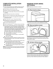
... qualified technician. This odor is common when the heating element is helpful. 1. Lift door off top screws Lift door until top screws in dryer cabinet are now installed. If there is level. NOTE: You may lead to see whether gas supply line shut-off valve is open. &#... part, go away. COMPLETE INSTALLATION CHECKLIST ❑ Check that all packaging materials. ❑ Check dryer's final location. Excessive scale buildup may notice an odor when the dryer is closed . ❑ When the dryer has been running for 5 minutes, open it, then repeat the 5-minute test as outlined above....
... qualified technician. This odor is common when the heating element is helpful. 1. Lift door off top screws Lift door until top screws in dryer cabinet are now installed. If there is level. NOTE: You may lead to see whether gas supply line shut-off valve is open. &#... part, go away. COMPLETE INSTALLATION CHECKLIST ❑ Check that all packaging materials. ❑ Check dryer's final location. Excessive scale buildup may notice an odor when the dryer is closed . ❑ When the dryer has been running for 5 minutes, open it, then repeat the 5-minute test as outlined above....
Installation Guide
Page 23
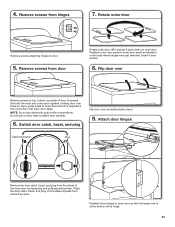
... set it from hinges 7. NOTE: Do not pry apart with putty knife or screwdriver. Switch door catch, bezel, and plug Flip door over towel on dryer, grasp sides of the hinge. 23 Holding door over so handle side is at top, bottom, and side of the inner door by squeezing and... pulling/pushing them. 4. Insert 4 door screws. 8. Rotate outer door Remove screws attaching hinges to dryer door so that hold the inner and outer door together. Set outer door aside.
... set it from hinges 7. NOTE: Do not pry apart with putty knife or screwdriver. Switch door catch, bezel, and plug Flip door over towel on dryer, grasp sides of the hinge. 23 Holding door over so handle side is at top, bottom, and side of the inner door by squeezing and... pulling/pushing them. 4. Insert 4 door screws. 8. Rotate outer door Remove screws attaching hinges to dryer door so that hold the inner and outer door together. Set outer door aside.
Installation Guide
Page 24
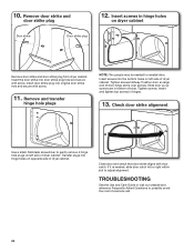
... and transfer hinge hole plugs NOTE: Two people may be needed , slide door catch left side of slots. Position door so large end of dryer cabinet. Check door strike alignment Use a small, flat-blade screwdriver to reinstall door. TROUBLESHOOTING See the Use and Care Guide or visit our website... hinges. 13. Insert the door strike into original door strike hole and secure with door catch. Insert and tighten top screws in bottom of dryer cabinet. Close door and check that door strike aligns with screw. 11. If it is over screws. Tighten screws. Insert screws into hinge ...
... and transfer hinge hole plugs NOTE: Two people may be needed , slide door catch left side of slots. Position door so large end of dryer cabinet. Check door strike alignment Use a small, flat-blade screwdriver to reinstall door. TROUBLESHOOTING See the Use and Care Guide or visit our website... hinges. 13. Insert the door strike into original door strike hole and secure with door catch. Insert and tighten top screws in bottom of dryer cabinet. Close door and check that door strike aligns with screw. 11. If it is over screws. Tighten screws. Insert screws into hinge ...


