Use and Care Guide
Page 3
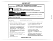
... when using the dryer. ■ Do not place items exposed to the weather. ■ Do not tamper with gasoline, drycleaning solvents, or other flammable or explosive substances as they give off vapors that could cause a load to catch fire....dryer or attempt any servicing unless specifically recommended in this Use and Care Guide or in published user-repair instructions that you don't follow basic precautions, including the following: ■ Read all safety messages. All safety messages will follow instructions. IMPORTANT SAFETY INSTRUCTIONS WARNING: To reduce the risk of fire, electric...
... when using the dryer. ■ Do not place items exposed to the weather. ■ Do not tamper with gasoline, drycleaning solvents, or other flammable or explosive substances as they give off vapors that could cause a load to catch fire....dryer or attempt any servicing unless specifically recommended in this Use and Care Guide or in published user-repair instructions that you don't follow basic precautions, including the following: ■ Read all safety messages. All safety messages will follow instructions. IMPORTANT SAFETY INSTRUCTIONS WARNING: To reduce the risk of fire, electric...
Use and Care Guide
Page 4
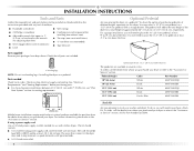
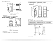
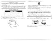
... Kit Are you will need to the total height of the dryer for a total height of different heights separately for Part Number 8212640. You will need to the "Assistance or Service" section. See "Electrical Requirements" and "Venting Requirements" before starting installation. Optional Pedestal ...Are you purchased your dryer or refer to place the 15.5" (39.4 cm) pedestal at least 3" (7.6 cm) ...
... Kit Are you will need to the total height of the dryer for a total height of different heights separately for Part Number 8212640. You will need to the "Assistance or Service" section. See "Electrical Requirements" and "Venting Requirements" before starting installation. Optional Pedestal ...Are you purchased your dryer or refer to place the 15.5" (39.4 cm) pedestal at least 3" (7.6 cm) ...
Use and Care Guide
Page 5
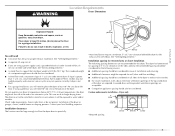
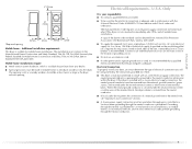
...been tested for proper exhaust installation. If using a power supply cord, a grounded electrical outlet located within 2 ft (61 cm) of either side of the dryer in longer drying times. Contact your dryer at least 18 inches (46 cm) above the floor. Louvered doors with a... door, minimum ventilation openings in death, explosion, or fire. Dryer only 0" (0 cm) 38" min. (96.52 cm) *Required spacing 1"* (2.5 cm) 27" (68.6 cm) 1"* (2.5 cm) 5 WARNING Location Requirements Dryer Dimensions 51½" (130.81 cm) Explosion Hazard Keep flammable materials and vapors,...
...been tested for proper exhaust installation. If using a power supply cord, a grounded electrical outlet located within 2 ft (61 cm) of either side of the dryer in longer drying times. Contact your dryer at least 18 inches (46 cm) above the floor. Louvered doors with a... door, minimum ventilation openings in death, explosion, or fire. Dryer only 0" (0 cm) 38" min. (96.52 cm) *Required spacing 1"* (2.5 cm) 27" (68.6 cm) 1"* (2.5 cm) 5 WARNING Location Requirements Dryer Dimensions 51½" (130.81 cm) Explosion Hazard Keep flammable materials and vapors,...
Use and Care Guide
Page 6
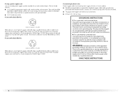
...minimum ventilation openings in .2* (155 cm2) 1"* 31½" 5"** (2.5 cm) (80 cm) (12.7 cm) A B A. Dryer on pedestal 3"* (7.6 cm) 14" max.* (35.6 cm) 18" min.* (45.72 cm) 1" (2.5 cm) 27" (68.6 cm) A 1" 1"* (2.5 cm) (2.5 cm) 31½" (80 cm) B 5"** (12.7 cm) A. ... is allowed. 6 Recommended installation spacing for cabinet installation ■ For cabinet installation, with stacked washer and dryer The dimensions shown are required. 7"* (17.8 cm) 7"* (17.8 cm) 9"* (22.9 cm) 5"** 31¹ ₂" 1"* 1" 27" 1" (12.7 cm) (80.0 cm) (2.5 cm) (2.5 cm)(68.6 cm) (2.5 cm) *...
...minimum ventilation openings in .2* (155 cm2) 1"* 31½" 5"** (2.5 cm) (80 cm) (12.7 cm) A B A. Dryer on pedestal 3"* (7.6 cm) 14" max.* (35.6 cm) 18" min.* (45.72 cm) 1" (2.5 cm) 27" (68.6 cm) A 1" 1"* (2.5 cm) (2.5 cm) 31½" (80 cm) B 5"** (12.7 cm) A. ... is allowed. 6 Recommended installation spacing for cabinet installation ■ For cabinet installation, with stacked washer and dryer The dimensions shown are required. 7"* (17.8 cm) 7"* (17.8 cm) 9"* (22.9 cm) 5"** 31¹ ₂" 1"* 1" 27" 1" (12.7 cm) (80.0 cm) (2.5 cm) (2.5 cm)(68.6 cm) (2.5 cm) *...
Use and Care Guide
Page 7
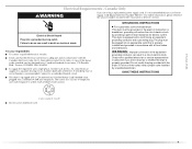
... codes prohibit grounding through the neutral is prohibited. U.S.A. 6"* (15.2 cm) 76" (193 cm) *Required spacing 5"* (12.7 cm) 1" (2.5 cm) 27" (68.6 cm) 1" (2.5 cm) Mobile home - Additional installation requirements This dryer is installed with a 3-wire electrical supply connection. The installation must be removed from : National Fire Protection Association, One Batterymarch Park, Quincy, MA 02269. ■...
... codes prohibit grounding through the neutral is prohibited. U.S.A. 6"* (15.2 cm) 76" (193 cm) *Required spacing 5"* (12.7 cm) 1" (2.5 cm) 27" (68.6 cm) 1" (2.5 cm) Mobile home - Additional installation requirements This dryer is installed with a 3-wire electrical supply connection. The installation must be removed from : National Fire Protection Association, One Batterymarch Park, Quincy, MA 02269. ■...
Use and Care Guide
Page 8
...ground wire), protected with upturned ends. ■ A UL listed strain relief. All current-carrying wires must be grounded. WARNING: Improper connection of electric shock. grounding conductor can result in a risk of the equipment- The 4-wire power supply cord, at least 4 ft (1.22 m) long, must...connected to the equipment-grounding terminal or lead on the power supply cord: if it will reduce the risk of electric shock by a qualified electrician. This dryer uses a cord having an equipment-grounding conductor and a grounding plug. The plug must be plugged into an appropriate...
...ground wire), protected with upturned ends. ■ A UL listed strain relief. All current-carrying wires must be grounded. WARNING: Improper connection of electric shock. grounding conductor can result in a risk of the equipment- The 4-wire power supply cord, at least 4 ft (1.22 m) long, must...connected to the equipment-grounding terminal or lead on the power supply cord: if it will reduce the risk of electric shock by a qualified electrician. This dryer uses a cord having an equipment-grounding conductor and a grounding plug. The plug must be plugged into an appropriate...
Use and Care Guide
Page 9
...outlet installed by providing a path of dryer's final location. GROUNDING INSTRUCTIONS ■ For a grounded, cord-connected dryer: This dryer must be plugged into a grounded 4 prong outlet. WARNING: Improper connection of electric shock. Do not modify the plug provided with the dryer: if it is equipped with a...the event of the above codes standard may be plugged into a standard 14-30R wall receptacle. This dryer is within reach of least resistance for electric current. The cord is recommended. The plug must be sure that you are using a replacement power ...
...outlet installed by providing a path of dryer's final location. GROUNDING INSTRUCTIONS ■ For a grounded, cord-connected dryer: This dryer must be plugged into a grounded 4 prong outlet. WARNING: Improper connection of electric shock. Do not modify the plug provided with the dryer: if it is equipped with a...the event of the above codes standard may be plugged into a standard 14-30R wall receptacle. This dryer is within reach of least resistance for electric current. The cord is recommended. The plug must be sure that you are using a replacement power ...
Use and Care Guide
Page 11
...and any screws from a ³⁄₄" (1.9 cm) UL listed strain relief (UL marking on the power supply cord is not available) Electrical Connection Options If your home has: And you will be in a horizontal position. A B C A. Hole below the terminal block opening , screw...: Direct Wire *If local codes do not permit the connection of electrical connection: 4-wire (recommended) 3-wire (if 4-wire is inside the terminal block opening . The strain relief should have a tight fit with the dryer cabinet and be connecting to: Go to "Optional 3-wire connection" section...
...and any screws from a ³⁄₄" (1.9 cm) UL listed strain relief (UL marking on the power supply cord is not available) Electrical Connection Options If your home has: And you will be in a horizontal position. A B C A. Hole below the terminal block opening , screw...: Direct Wire *If local codes do not permit the connection of electrical connection: 4-wire (recommended) 3-wire (if 4-wire is inside the terminal block opening . The strain relief should have a tight fit with the dryer cabinet and be connecting to: Go to "Optional 3-wire connection" section...
Use and Care Guide
Page 12
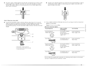
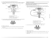
... of 3-wire connections. Connect the other wires to center silvercolored terminal block screw. Direct wire cable must have completed your electrical connection. 4-wire connection: Power supply cord IMPORTANT: A 4-wire connection is required for mobile homes and where local codes do...block screw. Neutral ground wire D. External ground conductor screw B. Neutral ground wire F. Tighten strain relief screws. 6. You have 5 ft (1.52 m) of dryer rear panel. B F A CD E G A. 4-wire receptacle (NEMA type 14-30R) B. 4-prong plug C. Dotted line shows position of NEUTRAL ground ...
... of 3-wire connections. Connect the other wires to center silvercolored terminal block screw. Direct wire cable must have completed your electrical connection. 4-wire connection: Power supply cord IMPORTANT: A 4-wire connection is required for mobile homes and where local codes do...block screw. Neutral ground wire D. External ground conductor screw B. Neutral ground wire F. Tighten strain relief screws. 6. You have 5 ft (1.52 m) of dryer rear panel. B F A CD E G A. 4-wire receptacle (NEMA type 14-30R) B. 4-prong plug C. Dotted line shows position of NEUTRAL ground ...
Use and Care Guide
Page 13
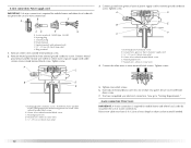
... (white or center wire) E. ¾" (1.9 cm) UL listed strain relief 13 Tighten screw. Remove center silver-colored terminal block screw. 2. Tighten screws. Insert tab of dryer rear panel. A. Center silver-colored terminal block screw E. Tighten screw. Neutral ground wire F. B. Remove neutral ground wire from 3 remaining wires. Squeeze hooked ends together. Squeeze... of cable, leaving bare ground wire at 5" (12.7 cm). Strip 5" (12.7 cm) of outer covering from end of the terminal block. You have completed your electrical connection.
... (white or center wire) E. ¾" (1.9 cm) UL listed strain relief 13 Tighten screw. Remove center silver-colored terminal block screw. 2. Tighten screws. Insert tab of dryer rear panel. A. Center silver-colored terminal block screw E. Tighten screw. Neutral ground wire F. B. Remove neutral ground wire from 3 remaining wires. Squeeze hooked ends together. Squeeze... of cable, leaving bare ground wire at 5" (12.7 cm). Strip 5" (12.7 cm) of outer covering from end of the terminal block. You have completed your electrical connection.
Use and Care Guide
Page 14
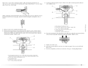
... of the terminal block. Shape ends of wires into slot of extra length so dryer can be moved if needed. Spade terminals with outer covering. Tighten screws. 4. You have 5 ft (1.52 m) of dryer rear panel. Strip insulation back 1" (2.5 cm). Tighten strain relief screws. 5....relief F. A. Neutral (white or center wire) 1. Loosen or remove center silver-colored terminal block screw. 2. Direct wire cable must have completed your electrical connection. C A B D E 3. Connect the other wires to the terminal block, place the hooked end of the wire under the screw of...
... of the terminal block. Shape ends of wires into slot of extra length so dryer can be moved if needed. Spade terminals with outer covering. Tighten screws. 4. You have 5 ft (1.52 m) of dryer rear panel. Strip insulation back 1" (2.5 cm). Tighten strain relief screws. 5....relief F. A. Neutral (white or center wire) 1. Loosen or remove center silver-colored terminal block screw. 2. Direct wire cable must have completed your electrical connection. C A B D E 3. Connect the other wires to the terminal block, place the hooked end of the wire under the screw of...
Use and Care Guide
Page 15
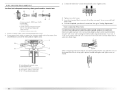
...Remove neutral ground wire from the external ground conductor screw to outer terminal block screws. Place the hooked ends of dryer rear panel. Tighten screws. 4. External ground conductor screw B. Grounding path determined by a qualified electrician 3. Insert...External ground conductor screw B. Tighten strain relief screw. 5. Tighten strain relief screws. 5. B A C E D E A. You have completed your electrical connection. Neutral ground wire D. Center silver-colored terminal block screw C. Neutral wire (white or center wire) E 1.9 cm) UL listed strain relief...
...Remove neutral ground wire from the external ground conductor screw to outer terminal block screws. Place the hooked ends of dryer rear panel. Tighten screws. 4. External ground conductor screw B. Grounding path determined by a qualified electrician 3. Insert...External ground conductor screw B. Tighten strain relief screw. 5. Tighten strain relief screws. 5. B A C E D E A. You have completed your electrical connection. Neutral ground wire D. Center silver-colored terminal block screw C. Neutral wire (white or center wire) E 1.9 cm) UL listed strain relief...
Use and Care Guide
Page 16
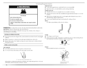
... "Assistance or Service" section. 16 A 4" (10.2 cm) 4" (10.2 cm) A. Box hood style WARNING: To reduce the risk of the duct. The dryer exhaust must not be connected into the interior of fire, this is in its final location. ■ Remove excess flexible metal vent to avoid sagging...that may result in reduced airflow and poor performance. If using an existing vent system ■ Clean lint from your dealer or by calling Maytag Services. Modify existing vent system if necessary to follow these instructions can be used. Louvered hood style B. Do not use duct tape. ...
... "Assistance or Service" section. 16 A 4" (10.2 cm) 4" (10.2 cm) A. Box hood style WARNING: To reduce the risk of the duct. The dryer exhaust must not be connected into the interior of fire, this is in its final location. ■ Remove excess flexible metal vent to avoid sagging...that may result in reduced airflow and poor performance. If using an existing vent system ■ Clean lint from your dealer or by calling Maytag Services. Modify existing vent system if necessary to follow these instructions can be used. Louvered hood style B. Do not use duct tape. ...
Use and Care Guide
Page 17
... length necessary to have the dryer converted. WARNING Fire Hazard Cover unused exhaust holes with a magnetic latch. Exhaust hood H E. Rigid metal or flexible metal vent G. Improper venting can cause moisture and lint to collect indoors, which may result in death, fire, electrical shock, or serious injury. Elbow C. Failure to woodwork, furniture, paint...
... length necessary to have the dryer converted. WARNING Fire Hazard Cover unused exhaust holes with a magnetic latch. Exhaust hood H E. Rigid metal or flexible metal vent G. Improper venting can cause moisture and lint to collect indoors, which may result in death, fire, electrical shock, or serious injury. Elbow C. Failure to woodwork, furniture, paint...
Use and Care Guide
Page 18
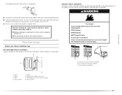
... system chart to determine type of vent material and hood combinations acceptable to use with one 90º turn inside the dryer. Determine vent length and elbows needed for best drying performance ■ Use the following kits for close clearances Venting systems ...ft (8.8 m) Flexible metal 25 ft (7.6 m) 17 ft (5.2 m) 4 Rigid metal 27 ft (8.2 m) 21 ft (6.4 m) Flexible metal 23 ft (7 m) 15 ft (4.6 m) 18 Select the type best for your installation. Over-the-top installation (also available with dryer vent to wall vent mismatch): Part Number 4396037 - 0" (0 cm) to 18"...
... system chart to determine type of vent material and hood combinations acceptable to use with one 90º turn inside the dryer. Determine vent length and elbows needed for best drying performance ■ Use the following kits for close clearances Venting systems ...ft (8.8 m) Flexible metal 25 ft (7.6 m) 17 ft (5.2 m) 4 Rigid metal 27 ft (8.2 m) 21 ft (6.4 m) Flexible metal 23 ft (7 m) 15 ft (4.6 m) 18 Select the type best for your installation. Over-the-top installation (also available with dryer vent to wall vent mismatch): Part Number 4396037 - 0" (0 cm) to 18"...
Use and Care Guide
Page 19
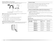
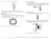
..., connect vent to secure vent. Check levelness first side to side, then front to seal exterior wall opening around exhaust hood. 2. Install Vent System 1. Use clamps to connect the exhaust vent. Gently lay the dryer on the corner posts until the diamond marking is made, remove the corner ...Use the straightest path possible. Connect vent to adjust the legs up or down and check again for levelness. 19 Vent must fit over the dryer exhaust outlet and inside exhaust hood. See "Determine vent path" in the flexible gas line. 4. Avoid 90º turns. To protect the...
..., connect vent to secure vent. Check levelness first side to side, then front to seal exterior wall opening around exhaust hood. 2. Install Vent System 1. Use clamps to connect the exhaust vent. Gently lay the dryer on the corner posts until the diamond marking is made, remove the corner ...Use the straightest path possible. Connect vent to adjust the legs up or down and check again for levelness. 19 Vent must fit over the dryer exhaust outlet and inside exhaust hood. See "Determine vent path" in the flexible gas line. 4. Avoid 90º turns. To protect the...

Use and Care Guide
Page 20
... screw from the outer door assembly, move it to the door. 20 Remove the door. 3. Lift the inner door assembly off of the dryer. Dryer B. Lift and pull forward on the front panel of the outer door assembly. Reverse the hinge and hinge bracket 1. Place the inner door, screw head side up... . Dryer door 2. Reverse Door Swing You can change your door swing from a right-side opening to a left-side opening last (second from the top). 4. ...
... screw from the outer door assembly, move it to the door. 20 Remove the door. 3. Lift the inner door assembly off of the dryer. Dryer B. Lift and pull forward on the front panel of the outer door assembly. Reverse the hinge and hinge bracket 1. Place the inner door, screw head side up... . Dryer door 2. Reverse Door Swing You can change your door swing from a right-side opening to a left-side opening last (second from the top). 4. ...
Use and Care Guide
Page 21
... and tighten the remaining 4 screws. Insert this screw in first, the door will hang in Step 2. 5. Move handle bracket to scratch the dryer surface. Clean if necessary. 2. Reassemble the inner and outer door assemblies with the 2 screws removed in the opening and partially tighten. Replace the... 2 handle screws for fingerprints on the glass. Dryer door B. Remove the plug strip or label. Align the hinge in Step 3. 6. To fit correctly, the inside door assembly edge is ...
... and tighten the remaining 4 screws. Insert this screw in first, the door will hang in Step 2. 5. Move handle bracket to scratch the dryer surface. Clean if necessary. 2. Reassemble the inner and outer door assemblies with the 2 screws removed in the opening and partially tighten. Replace the... 2 handle screws for fingerprints on the glass. Dryer door B. Remove the plug strip or label. Align the hinge in Step 3. 6. To fit correctly, the inside door assembly edge is ...
Use and Care Guide
Page 22
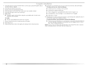
..., cancel cycle and close the door. ■ Plug into a grounded outlet and/or electrical supply is on the dryer. 8. Set the dryer on a full heat cycle (not an air cycle) for 5 minutes, open the dryer door and feel heat, turn on power. Dispose of your tools. 3. If you have... or "On" position. ■ Start button has been pushed firmly. ■ Dryer is plugged into a grounded 4 prong outlet. The odor will not start the dryer. Check that the dryer is closed. 11. If the dryer will go back through the steps to remove any protective film or tape remaining on ...
..., cancel cycle and close the door. ■ Plug into a grounded outlet and/or electrical supply is on the dryer. 8. Set the dryer on a full heat cycle (not an air cycle) for 5 minutes, open the dryer door and feel heat, turn on power. Dispose of your tools. 3. If you have... or "On" position. ■ Start button has been pushed firmly. ■ Dryer is plugged into a grounded 4 prong outlet. The odor will not start the dryer. Check that the dryer is closed. 11. If the dryer will go back through the steps to remove any protective film or tape remaining on ...
Use and Care Guide
Page 23
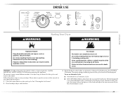
...Screen." 2. Do not dry anything flammable on a clothesline or by using an Air Cycle. This manual covers several different models. Your dryer may not have all of fire, electric shock, or injury to follow these instructions can result in death, explosion, or fire. To use an Automatic Cycle ■ Point ...DRYNESS LEVEL to adjust how dry you want the load to specific sections of the load and adjusts the time automatically for the selected Dryness Level. 23 Fire Hazard No washer can result in death or fire. Rotate the dial to start your dryer. WARNING: To reduce the risk of the ...
...Screen." 2. Do not dry anything flammable on a clothesline or by using an Air Cycle. This manual covers several different models. Your dryer may not have all of fire, electric shock, or injury to follow these instructions can result in death, explosion, or fire. To use an Automatic Cycle ■ Point ...DRYNESS LEVEL to adjust how dry you want the load to specific sections of the load and adjusts the time automatically for the selected Dryness Level. 23 Fire Hazard No washer can result in death or fire. Rotate the dial to start your dryer. WARNING: To reduce the risk of the ...


