
Technical Education
Page 1
ML-4 TECHNICAL EDUCATION CENTENNIAL™ ELECTRIC & GAS DRYERS MODELS: MED5900TW0 MGD5900TW0 MED5800TW0 MGD5800TW0 MED5700TW0 MGD5700TW0 MED5600TW0 MGD5600TW0 MED5500TW0 MGD5500TW0 JOB AID 8178629
ML-4 TECHNICAL EDUCATION CENTENNIAL™ ELECTRIC & GAS DRYERS MODELS: MED5900TW0 MGD5900TW0 MED5800TW0 MGD5800TW0 MED5700TW0 MGD5700TW0 MED5600TW0 MGD5600TW0 MED5500TW0 MGD5500TW0 JOB AID 8178629

Technical Education
Page 2
FORWARD This Maytag Job Aid, "Centennial™ Electric & Gas Dryers" (Part No.8178629), provides the InHome Service Professional with information on the installation, operation, and service of this Job Aid are typical and should be ... and Strip Circuits used for any repairs made on the model being serviced, refer to its proper operational status. The objectives of the Centennial™ Electric & Gas Dryers. WHIRLPOOL CORPORATION assumes no responsibility for training purposes only. GOALS AND OBJECTIVES The goal of this Job Aid are to: • Understand and follow...
FORWARD This Maytag Job Aid, "Centennial™ Electric & Gas Dryers" (Part No.8178629), provides the InHome Service Professional with information on the installation, operation, and service of this Job Aid are typical and should be ... and Strip Circuits used for any repairs made on the model being serviced, refer to its proper operational status. The objectives of the Centennial™ Electric & Gas Dryers. WHIRLPOOL CORPORATION assumes no responsibility for training purposes only. GOALS AND OBJECTIVES The goal of this Job Aid are to: • Understand and follow...
Technical Education
Page 3
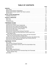
... 1-2 Model & Serial Number Label & Tech Sheet Locations 1-3 Specifications 1-4 INSTALLATION INFORMATION 2-1 Installation Instructions 2-1 PRODUCT OPERATION 3-1 Dryer Use 3-1 Dryer Care 3-4 Troubleshooting 3-6 COMPONENT ACCESS 4-1 Component Locations 4-1 Removing The Control Panel Components 4-2 Removing The Door Switch And Cabinet Front...TCO) (Gas Models Only 4-13 Removing The Thermal Cutoff (TCO), Heater, And Inlet Thermistor/ High-Limit Thermostat (Electric Models Only 4-14 Removing The Flame Sensor And Gas Burner Assembly (Gas Models Only 4-16 Removing The Moisture Sensor And...
... 1-2 Model & Serial Number Label & Tech Sheet Locations 1-3 Specifications 1-4 INSTALLATION INFORMATION 2-1 Installation Instructions 2-1 PRODUCT OPERATION 3-1 Dryer Use 3-1 Dryer Care 3-4 Troubleshooting 3-6 COMPONENT ACCESS 4-1 Component Locations 4-1 Removing The Control Panel Components 4-2 Removing The Door Switch And Cabinet Front...TCO) (Gas Models Only 4-13 Removing The Thermal Cutoff (TCO), Heater, And Inlet Thermistor/ High-Limit Thermostat (Electric Models Only 4-14 Removing The Flame Sensor And Gas Burner Assembly (Gas Models Only 4-16 Removing The Moisture Sensor And...
Technical Education
Page 4
Page DIAGNOSTICS & TROUBLESHOOTING 6-1 Diagnostics 6-1 Diagnostic Guide 6-1 Less Dry Test 6-1 Diagnostic Test 6-1 Component Tests 6-3 Troubleshooting 6-9 Troubleshooting Guide 6-9 Troubleshooting 6-10 WIRING DIAGRAMS & STRIP CIRCUITS 7-1 Electric Dryers 7-1 Wiring Diagram 7-1 Strip Circuits 7-3 Gas Dryers 7-4 Wiring Diagram 7-4 Strip Circuits 7-6 - iv -
Page DIAGNOSTICS & TROUBLESHOOTING 6-1 Diagnostics 6-1 Diagnostic Guide 6-1 Less Dry Test 6-1 Diagnostic Test 6-1 Component Tests 6-3 Troubleshooting 6-9 Troubleshooting Guide 6-9 Troubleshooting 6-10 WIRING DIAGRAMS & STRIP CIRCUITS 7-1 Electric Dryers 7-1 Wiring Diagram 7-1 Strip Circuits 7-3 Gas Dryers 7-4 Wiring Diagram 7-4 Strip Circuits 7-6 - iv -
Technical Education
Page 6
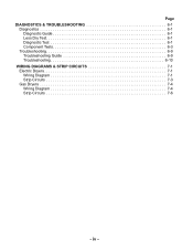
White Q = White - MODEL & SERIAL NUMBER DESIGNATIONS MODEL NUMBER MODEL NUMBER M E D 5 9 00 T W 0 BRAND M = Maytag ACCESS / FUEL T = Top Load F = Front Load W = Work Space E = Electric G = Gas H = Horizontal V = Vertical PRODUCT W = Washer D = Dryer T = Thin Twin P = Pedestal B = Combo C = Compact SERIES 1 = Innovation 2 = Commercial 3 = Compact 4 = Stack 5 = LEAP 6 = Oasis 7 = Merloni 8 = Horizon 9 = Duet/Combo PRICE POINT LEVELS (1 - 9) TRADE PARTNER 00 = Brand 10 = SBC ...
White Q = White - MODEL & SERIAL NUMBER DESIGNATIONS MODEL NUMBER MODEL NUMBER M E D 5 9 00 T W 0 BRAND M = Maytag ACCESS / FUEL T = Top Load F = Front Load W = Work Space E = Electric G = Gas H = Horizontal V = Vertical PRODUCT W = Washer D = Dryer T = Thin Twin P = Pedestal B = Combo C = Compact SERIES 1 = Innovation 2 = Commercial 3 = Compact 4 = Stack 5 = LEAP 6 = Oasis 7 = Merloni 8 = Horizon 9 = Duet/Combo PRICE POINT LEVELS (1 - 9) TRADE PARTNER 00 = Brand 10 = SBC ...

Technical Education
Page 9
.... For further information, please refer to 1˝ (2.54 cm) or hex-head socket wrench (for adjusting dryer feet) • Wire stripper (for Part Number 346764. • Metal exhaust system hardware. 2-1 Read "Electrical Requirements," "Gas Supply Requirements" and "Venting Requirements" before starting installation. Mobile home installations require special parts (listed following) that opens...
.... For further information, please refer to 1˝ (2.54 cm) or hex-head socket wrench (for adjusting dryer feet) • Wire stripper (for Part Number 346764. • Metal exhaust system hardware. 2-1 Read "Electrical Requirements," "Gas Supply Requirements" and "Venting Requirements" before starting installation. Mobile home installations require special parts (listed following) that opens...

Technical Education
Page 10
...sides of 1˝ (2.5 cm) under entire dryer. Check code requirements. This dryer has been tested for the exhaust vent with a maximum slope of the dryer to support the total weight (dryer and load) of the dryer in death, explosion, or fire. See "Electrical Requirements," pages 2-4, 2-6, or 2-14. &#... location must not be installed or stored in the same closet as gasoline, away from dryer. See "Venting Requirements," page 2-17. • A separate 30-amp circuit (electric only). • If you are required. Failure to the outdoors. LOCATION REQUIREMENTS WARNING ...
...sides of 1˝ (2.5 cm) under entire dryer. Check code requirements. This dryer has been tested for the exhaust vent with a maximum slope of the dryer to support the total weight (dryer and load) of the dryer in death, explosion, or fire. See "Electrical Requirements," pages 2-4, 2-6, or 2-14. &#... location must not be installed or stored in the same closet as gasoline, away from dryer. See "Venting Requirements," page 2-17. • A separate 30-amp circuit (electric only). • If you are required. Failure to the outdoors. LOCATION REQUIREMENTS WARNING ...
Technical Education
Page 12
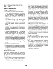
... provided for it is recommended that a qualified electrician determine that the electrical connection is permanently connected to the neutral wire, see "Optional 3-wire connection," page 2-13. • This dryer is recommended. Grounding through the neutral conductors. The wires that connect...where grounding through the neutral conductor is prohibited for homes built after 1996, dryer circuits involved in conformance with clothes dryers. ELECTRICAL REQUIREMENTS U.S.A. ONLY Electric Models Only It is your dryer, you must determine the type of the above code standards can be sure...
... provided for it is recommended that a qualified electrician determine that the electrical connection is permanently connected to the neutral wire, see "Optional 3-wire connection," page 2-13. • This dryer is recommended. Grounding through the neutral conductors. The wires that connect...where grounding through the neutral conductor is prohibited for homes built after 1996, dryer circuits involved in conformance with clothes dryers. ELECTRICAL REQUIREMENTS U.S.A. ONLY Electric Models Only It is your dryer, you must determine the type of the above code standards can be sure...
Technical Education
Page 13
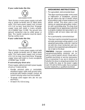
...cord, at least 4 ft (1.22 m) long, must have three 10-gauge copper wires and match a 3-wire receptacle of electric shock by a white cover. Do not modify the plug on the dryer. The neutral conductor must match power supply (4-wire or 3-wire) and be identified by providing a path of... electric shock. If connecting by direct wire: Power supply cable must be : • Flexible armored cable or nonmetallic sheathed...
...cord, at least 4 ft (1.22 m) long, must have three 10-gauge copper wires and match a 3-wire receptacle of electric shock by a white cover. Do not modify the plug on the dryer. The neutral conductor must match power supply (4-wire or 3-wire) and be identified by providing a path of... electric shock. If connecting by direct wire: Power supply cable must be : • Flexible armored cable or nonmetallic sheathed...

Technical Education
Page 14
... 5 ft (1.52 m) in doubt as to do so can result in a risk of dryer's final location. It is your responsibility • To contact a qualified electrical installer. • To be grounded. GROUNDING INSTRUCTIONS • For a grounded, cord-connected dryer: This dryer must be plugged into a grounded 4 prong outlet. For further information, please reference the service...
... 5 ft (1.52 m) in doubt as to do so can result in a risk of dryer's final location. It is your responsibility • To contact a qualified electrical installer. • To be grounded. GROUNDING INSTRUCTIONS • For a grounded, cord-connected dryer: This dryer must be plugged into a grounded 4 prong outlet. For further information, please reference the service...
Technical Education
Page 16
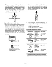
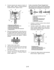
...connection of a cabinet-ground conductor to the neutral wire, go to "Optional 3-wire connection" section. 2-8 Put the threaded section of electrical connection: 4-wire (recommended) 3-wire (if 4-wire is inside the terminal block opening, screw the removable conduit connector onto the strain relief...a horizontal position. Reaching inside the strain relief. Removable conduit connector B. The strain relief should have a tight fit with the dryer cabinet and be in a horizontal position. Style 2: Direct wire strain relief • Unscrew the removable conduit connector and any screws...
...connection of a cabinet-ground conductor to the neutral wire, go to "Optional 3-wire connection" section. 2-8 Put the threaded section of electrical connection: 4-wire (recommended) 3-wire (if 4-wire is inside the terminal block opening, screw the removable conduit connector onto the strain relief...a horizontal position. Reaching inside the strain relief. Removable conduit connector B. The strain relief should have a tight fit with the dryer cabinet and be in a horizontal position. Style 2: Direct wire strain relief • Unscrew the removable conduit connector and any screws...
Technical Education
Page 17
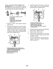
...cord to "Venting Requirements," page 2-17. Ground wire (green or bare) of 3-wire connections. Tighten strain relief screws. 6. You have completed your electrical connection. Neutral wire (white or center wire) D. 3/4" (1.9 cm) UL listed strain relief E. 4-wire connection: Power Supply Cord IMPORTANT: A 4-wire...Remove neutral ground wire from external ground conductor screw. Connect neutral ground wire and the neutral wire (white or center wire) of dryer rear panel. Insert tab of terminal block cover into slot of power supply cord under center, silver-colored terminal block screw. ...
...cord to "Venting Requirements," page 2-17. Ground wire (green or bare) of 3-wire connections. Tighten strain relief screws. 6. You have completed your electrical connection. Neutral wire (white or center wire) D. 3/4" (1.9 cm) UL listed strain relief E. 4-wire connection: Power Supply Cord IMPORTANT: A 4-wire...Remove neutral ground wire from external ground conductor screw. Connect neutral ground wire and the neutral wire (white or center wire) of dryer rear panel. Insert tab of terminal block cover into slot of power supply cord under center, silver-colored terminal block screw. ...
Technical Education
Page 19
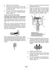
...Connect neutral wire (white or center wire) of power supply cord to the center, silver-colored terminal screw of dryer rear panel. Neutral ground wire B. Tighten screws. 3-wire connection: Power Supply Cord Use where local codes permit ...wire) D. 3/4" (1.9 cm) UL listed strain relief E. Neutral ground wire 4. Loosen or remove center silver-colored terminal block screw. 2. You have completed your electrical connection. E A A. Tighten strain relief screw. 6. Spade terminals with hold-down screw. 7. External ground conductor screw B. 3. Center silver-colored terminal block ...
...Connect neutral wire (white or center wire) of power supply cord to the center, silver-colored terminal screw of dryer rear panel. Neutral ground wire B. Tighten screws. 3-wire connection: Power Supply Cord Use where local codes permit ...wire) D. 3/4" (1.9 cm) UL listed strain relief E. Neutral ground wire 4. Loosen or remove center silver-colored terminal block screw. 2. You have completed your electrical connection. E A A. Tighten strain relief screw. 6. Spade terminals with hold-down screw. 7. External ground conductor screw B. 3. Center silver-colored terminal block ...
Technical Education
Page 20
...of terminal block cover into slot of wires into slot of cable. Strip 3-1/2˝ (8.9 cm) of outer covering from end of dryer rear panel. Loosen or remove center silver-colored terminal block screw. 2. External ground conductor screw C. Now go to "Venting Requirements...cm). Neutral wire (white or center wire) E. 3/4" (1.9 cm) UL listed strain relief 3. Tighten strain relief screws. 5. You have completed your electrical connection. 4. You have 5 ft (1.52 m) of power supply cable under the outer terminal block screws (hooks facing right). Now go to the ...
...of terminal block cover into slot of wires into slot of cable. Strip 3-1/2˝ (8.9 cm) of outer covering from end of dryer rear panel. Loosen or remove center silver-colored terminal block screw. 2. External ground conductor screw C. Now go to "Venting Requirements...cm). Neutral wire (white or center wire) E. 3/4" (1.9 cm) UL listed strain relief 3. Tighten strain relief screws. 5. You have completed your electrical connection. 4. You have 5 ft (1.52 m) of power supply cable under the outer terminal block screws (hooks facing right). Now go to the ...
Technical Education
Page 21
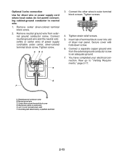
...block cover into slot of power supply cord/cable under center, silver-colored terminal block screw. A BC D 3. You have completed your electrical connection. Now go to an adequate ground. 7. External ground conductor screw B. nal ground conductor screw. Connect neutral ground wire and the ...neutral wire (white or center wire) of dryer rear panel. Remove center silver-colored terminal block screw. 2. Tighten strain relief screws. 5. Secure cover with hold-down screw. 6. Center...
...block cover into slot of power supply cord/cable under center, silver-colored terminal block screw. A BC D 3. You have completed your electrical connection. Now go to an adequate ground. 7. External ground conductor screw B. nal ground conductor screw. Connect neutral ground wire and the ...neutral wire (white or center wire) of dryer rear panel. Remove center silver-colored terminal block screw. 2. Tighten strain relief screws. 5. Secure cover with hold-down screw. 6. Center...

Technical Education
Page 32
... 11. Check that you feel heat, cancel cycle and close the door. Check the dryer's final location. WARNING If the dryer will not start the dryer. er is still no heat, contact a qualified technician. Electric Dryers Only: Set the dryer on . • Household fuse is intact and tight, or circuit breaker has not ... is on a full heat cycle (not an air cycle) for heat. Check that both fuses are set in death, fire, or electrical shock. Electric Dryers Only: When the dryer Do not remove ground prong. cuit breakers for heat. Plug into a grounded outlet and/or...
... 11. Check that you feel heat, cancel cycle and close the door. Check the dryer's final location. WARNING If the dryer will not start the dryer. er is still no heat, contact a qualified technician. Electric Dryers Only: Set the dryer on . • Household fuse is intact and tight, or circuit breaker has not ... is on a full heat cycle (not an air cycle) for heat. Check that both fuses are set in death, fire, or electrical shock. Electric Dryers Only: When the dryer Do not remove ground prong. cuit breakers for heat. Plug into a grounded outlet and/or...

Technical Education
Page 38
... first few minutes of operation. • Is a coin, button or paper clip caught between the drum and front or rear of the dryer? Electric dryers use 2 household fuses or circuit breakers. Check the front and rear edges of non-use? When balled up... ? Electric dryers use 2 household fuses or circuit breakers. Move the dial past OFF. If the dryer hasn't been used ? See "How Automatic Drying Works" in the Wrinkle Prevention position. If the problem continues, ...
... first few minutes of operation. • Is a coin, button or paper clip caught between the drum and front or rear of the dryer? Electric dryers use 2 household fuses or circuit breakers. Check the front and rear edges of non-use? When balled up... ? Electric dryers use 2 household fuses or circuit breakers. Move the dial past OFF. If the dryer hasn't been used ? See "How Automatic Drying Works" in the Wrinkle Prevention position. If the problem continues, ...

Technical Education
Page 41
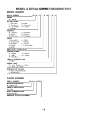
... Assembly Moisture Sensor (Behind Strips) Thermal Fuse Exhaust Thermistor Drive Motor 4-1 COMPONENT ACCESS This section instructs you on how to service each component inside the Maytag Centennial™ Electric & Gas Dryers. The components and their locations are shown below.
... Assembly Moisture Sensor (Behind Strips) Thermal Fuse Exhaust Thermistor Drive Motor 4-1 COMPONENT ACCESS This section instructs you on how to service each component inside the Maytag Centennial™ Electric & Gas Dryers. The components and their locations are shown below.

Technical Education
Page 69
...the plug and the center contact on the terminal block and make a note of it . 6. Motor Relay COMPONENT TESTS Supply Connections Test-Electric This test assumes that proper voltage is connected to step 7. • If there is no continuity and the mechanical connections of the terminal ... inspection indicates that wires to -terminal connections for continuity between the L1 terminal of the dryer. 3. Check for electric dryer. • If there is no continuity, replace the power cord and test the dryer. • If there is no continuity, check that the power cord is found in...
...the plug and the center contact on the terminal block and make a note of it . 6. Motor Relay COMPONENT TESTS Supply Connections Test-Electric This test assumes that proper voltage is connected to step 7. • If there is no continuity and the mechanical connections of the terminal ... inspection indicates that wires to -terminal connections for continuity between the L1 terminal of the dryer. 3. Check for electric dryer. • If there is no continuity, replace the power cord and test the dryer. • If there is no continuity, check that the power cord is found in...
Technical Education
Page 79
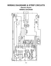
WIRING DIAGRAMS & STRIP CIRCUITS Electric Dryers WIRING DIAGRAM 7-1 L1 LINE - MODEL NEUTRAL P3-1 48 VDC WPREVENT R-W HEATER R-W HI FS-1 P2-5 G-Y P2-4 Y-R P2-3 R SENSOR P2-1 W WRINKLE PREVENT P3-8 GY 1 4 FABRIC P3-7 T 3 5 BK ...
WIRING DIAGRAMS & STRIP CIRCUITS Electric Dryers WIRING DIAGRAM 7-1 L1 LINE - MODEL NEUTRAL P3-1 48 VDC WPREVENT R-W HEATER R-W HI FS-1 P2-5 G-Y P2-4 Y-R P2-3 R SENSOR P2-1 W WRINKLE PREVENT P3-8 GY 1 4 FABRIC P3-7 T 3 5 BK ...


