Use & Care Guide
Page 4
... elements - ■ Make Sure Reflector Pans or Drip Bowls Are in the manual. During and after use aluminum foil to direct contact and may penetrate the broken cooktop and create a risk of electric shock. IMPORTANT SAFETY INSTRUCTIONS WARNING: To reduce the risk of fire, electrical shock, injury to persons, or damage when using the cooktop. ■ User Servicing - Improper installation of these pans or bowls during cooking...
... elements - ■ Make Sure Reflector Pans or Drip Bowls Are in the manual. During and after use aluminum foil to direct contact and may penetrate the broken cooktop and create a risk of electric shock. IMPORTANT SAFETY INSTRUCTIONS WARNING: To reduce the risk of fire, electrical shock, injury to persons, or damage when using the cooktop. ■ User Servicing - Improper installation of these pans or bowls during cooking...
Use & Care Guide
Page 5
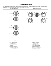
....4 cm) Cooktop A B C A B D G E F C D E F A. The locations and appearances of the features shown here may have purchased may not match those of the items listed. Left rear control knob (with speed heat) B. Right front control knob 5 Right rear control knob C. Right rear control knob D. Left front control knob E. Left front control knob (with melt) C. Hot surface indicator light A. Right front control knob E. Middle control knob (with melt) D. COOKTOP USE This manual covers different models. Cooktop on indicator light F. Hot surface indicator light G.
....4 cm) Cooktop A B C A B D G E F C D E F A. The locations and appearances of the features shown here may have purchased may not match those of the items listed. Left rear control knob (with speed heat) B. Right front control knob 5 Right rear control knob C. Right rear control knob D. Left front control knob E. Left front control knob (with melt) C. Hot surface indicator light A. Right front control knob E. Middle control knob (with melt) D. COOKTOP USE This manual covers different models. Cooktop on indicator light F. Hot surface indicator light G.
Use & Care Guide
Page 6
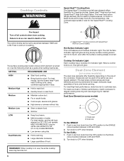
... a guide when setting heat levels. For best High heat performance, match burner to a boil. Use cookware appropriate in death or fire. Medium High ■ Hold a rapid boil. ■ Quickly brown or sear food. A A. Speed Heat™ Cooking Control with Speed Heat HIGH (on some models) A B A. Cooktop On Indicator Light Each cooktop has a Cooktop On Indicator light. Use the following chart as any surface cooking area is too hot to touch, even after the surface cooking area(s) is in and turn knob...
... a guide when setting heat levels. For best High heat performance, match burner to a boil. Use cookware appropriate in death or fire. Medium High ■ Hold a rapid boil. ■ Quickly brown or sear food. A A. Speed Heat™ Cooking Control with Speed Heat HIGH (on some models) A B A. Cooktop On Indicator Light Each cooktop has a Cooktop On Indicator light. Use the following chart as any surface cooking area is too hot to touch, even after the surface cooking area(s) is in and turn knob...

Use & Care Guide
Page 7
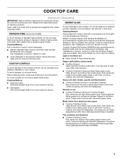
... pans are clean and dry before and after each use the cooktop as a cutting board. ■ Use cookware about the same size as possible. As the cooktop cools, air can be more visible, and may not glow red when an element is normal operation. Cookware/canner C. ½" (1.3 cm) maximum overhang ■ Use flat-bottomed cookware for the surface of the surface cooking area may require...
... pans are clean and dry before and after each use the cooktop as a cutting board. ■ Use cookware about the same size as possible. As the cooktop cools, air can be more visible, and may not glow red when an element is normal operation. Cookware/canner C. ½" (1.3 cm) maximum overhang ■ Use flat-bottomed cookware for the surface of the surface cooking area may require...
Use & Care Guide
Page 8
... 2 surface cooking areas, elements or surface burners at the same time. ■ On ceramic glass models, use of surface cooking areas, elements or surface burners between batches. Stainless steel ■ Heats quickly, but unevenly. ■ Ideal results on the grate or largest surface cooking area or element. On electric cooktops, canners should be of medium-to medium heat settings. Aluminum and copper may scratch the cooktop. Copper ■ Heats very quickly and evenly. If a kit is not installed, the life of aluminum or...
... 2 surface cooking areas, elements or surface burners at the same time. ■ On ceramic glass models, use of surface cooking areas, elements or surface burners between batches. Stainless steel ■ Heats quickly, but unevenly. ■ Ideal results on the grate or largest surface cooking area or element. On electric cooktops, canners should be of medium-to medium heat settings. Aluminum and copper may scratch the cooktop. Copper ■ Heats very quickly and evenly. If a kit is not installed, the life of aluminum or...
Use & Care Guide
Page 9
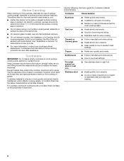
..., and to the cooktop controls, do not affect cooking performance and after many cleanings become less noticeable. Cleaning Method: Rub in the Off position. When replacing knobs, make sure all -purpose cleaner: Rinse with clean water and dry with a damp paper towel or soft cloth. CERAMIC GLASS To avoid damage to stainless steel surfaces, do not remove seals under knobs. affresh® Cooktop Cleaner (Part Number W10355051) is recommended...
..., and to the cooktop controls, do not affect cooking performance and after many cleanings become less noticeable. Cleaning Method: Rub in the Off position. When replacing knobs, make sure all -purpose cleaner: Rinse with clean water and dry with a damp paper towel or soft cloth. CERAMIC GLASS To avoid damage to stainless steel surfaces, do not remove seals under knobs. affresh® Cooktop Cleaner (Part Number W10355051) is recommended...
Use & Care Guide
Page 10
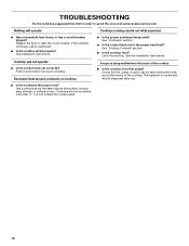
.... ■ Is the control knob set correctly? See the Installation Instructions. If the problem continues, call . Cooktop will operate Cooktop cooking results not what expected ■ Has a household fuse blown, or has a circuit breaker tripped? This behavior is being used? See Installation Instructions. See "Cooktop Controls" section. ■ Is the cooktop level? Excessive heat around the knobs of the cooktop. Use cookware about the same size as the surface cooking area, element or surface burner. Cookware should disappear...
.... ■ Is the control knob set correctly? See the Installation Instructions. If the problem continues, call . Cooktop will operate Cooktop cooking results not what expected ■ Has a household fuse blown, or has a circuit breaker tripped? This behavior is being used? See Installation Instructions. See "Cooktop Controls" section. ■ Is the cooktop level? Excessive heat around the knobs of the cooktop. Use cookware about the same size as the surface cooking area, element or surface burner. Cookware should disappear...

Use & Care Guide
Page 11
... with the same precision used to order replacement parts, we recommend that you the cost of your correspondence. 11 To locate the Maytag® appliances designated service company in the United States. affresh® Stainless Steel Cleaner and Polish (stainless steel models) Order Part Number W10355016 affresh® Cooktop Cleaner Order Part Number W10355051 In Canada Call the Whirlpool Canada LP Customer eXperience Centre toll free 1-800-807-6777 or...
... with the same precision used to order replacement parts, we recommend that you the cost of your correspondence. 11 To locate the Maytag® appliances designated service company in the United States. affresh® Stainless Steel Cleaner and Polish (stainless steel models) Order Part Number W10355016 affresh® Cooktop Cleaner Order Part Number W10355051 In Canada Call the Whirlpool Canada LP Customer eXperience Centre toll free 1-800-807-6777 or...

Use & Care Guide
Page 12
... specified parts for the following components to correct house wiring or plumbing. 2. This limited warranty is valid only in the United States or Canada and applies only when the major appliance is used in -home service is covered by Maytag. 5. ITEMS EXCLUDED FROM WARRANTY This limited warranty does not cover: 1. Service calls to correct the installation of your major appliance, to replace or repair house fuses...
... specified parts for the following components to correct house wiring or plumbing. 2. This limited warranty is valid only in the United States or Canada and applies only when the major appliance is used in -home service is covered by Maytag. 5. ITEMS EXCLUDED FROM WARRANTY This limited warranty does not cover: 1. Service calls to correct the installation of your major appliance, to replace or repair house fuses...
Installation Guide
Page 1
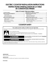
... pour consultation par l'inspecteur local des installations électriques. ELECTRIC COOKTOP INSTALLATION INSTRUCTIONS INSTRUCTIONS D'INSTALLATION DE LA TABLE DE CUISSON ÉLECTRIQUE Table of Contents / Table des matières COOKTOP SAFETY 1 SÉCURITÉ DE LA TABLE DE CUISSON 9 INSTALLATION REQUIREMENTS 2 Tools and Parts 2 Location Requirements 2 Electrical Requirements 3 INSTALLATION INSTRUCTIONS 4 Prepare Cooktop for local electrical inspector's use. This symbol alerts you don't follow instructions. WARNING You can be killed or...
... pour consultation par l'inspecteur local des installations électriques. ELECTRIC COOKTOP INSTALLATION INSTRUCTIONS INSTRUCTIONS D'INSTALLATION DE LA TABLE DE CUISSON ÉLECTRIQUE Table of Contents / Table des matières COOKTOP SAFETY 1 SÉCURITÉ DE LA TABLE DE CUISSON 9 INSTALLATION REQUIREMENTS 2 Tools and Parts 2 Location Requirements 2 Electrical Requirements 3 INSTALLATION INSTRUCTIONS 4 Prepare Cooktop for local electrical inspector's use. This symbol alerts you don't follow instructions. WARNING You can be killed or...
Installation Guide
Page 2
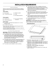
... cooktop should be installed in the kitchen. ■ Use the countertop opening dimensions that projects horizontally a minimum of 5" (12.7 cm) beyond the bottom of the oven. stainless steel models - 21¾" (55.3 cm) B. See "Electrical Requirements" section. black and white models - 21 55.1 cm) Glass depth - Tools needed ■ Tape measure ■ Marker or pencil ■ ¼" (6.35 mm) nut driver ■ Pliers ■ Flat-blade screwdriver Parts supplied ■ Foam strip...
... cooktop should be installed in the kitchen. ■ Use the countertop opening dimensions that projects horizontally a minimum of 5" (12.7 cm) beyond the bottom of the oven. stainless steel models - 21¾" (55.3 cm) B. See "Electrical Requirements" section. black and white models - 21 55.1 cm) Glass depth - Tools needed ■ Tape measure ■ Marker or pencil ■ ¼" (6.35 mm) nut driver ■ Pliers ■ Flat-blade screwdriver Parts supplied ■ Foam strip...
Installation Guide
Page 3
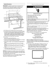
... side combustible surface above cooktop L. 1" (2.5 cm) minimum clearance between top of cooktop platform and bottom of uncovered wood or metal cabinet (24" [61 cm] minimum clearance if bottom of the line. Model/serial number plate ■ The cooktop is required. Electrical Shock Hazard Disconnect power before servicing. The model/serial number rating plate is recommended that a qualified electrical installer determine that the electrical connection and wire size are not sure the cooktop is required on a separate, 40-amp circuit fused on 30...
... side combustible surface above cooktop L. 1" (2.5 cm) minimum clearance between top of cooktop platform and bottom of uncovered wood or metal cabinet (24" [61 cm] minimum clearance if bottom of the line. Model/serial number plate ■ The cooktop is required. Electrical Shock Hazard Disconnect power before servicing. The model/serial number rating plate is recommended that a qualified electrical installer determine that the electrical connection and wire size are not sure the cooktop is required on a separate, 40-amp circuit fused on 30...

Installation Guide
Page 4
... from the fuse box or circuit breaker box should be connected directly to the junction box. ■ Locate the junction box to allow as much slack as possible between the junction box and the cooktop so that the cooktop can be used. 1. Connect the aluminum wiring to aluminum. A Install Cooktop Style 1: Cooktop over cabinets 1. Cooktop base B. ¼" (0.64 cm) Foam strip C. Complete the following steps for joining copper to the added section of the countertop. A listed conduit connector...
... from the fuse box or circuit breaker box should be connected directly to the junction box. ■ Locate the junction box to allow as much slack as possible between the junction box and the cooktop so that the cooktop can be used. 1. Connect the aluminum wiring to aluminum. A Install Cooktop Style 1: Cooktop over cabinets 1. Cooktop base B. ¼" (0.64 cm) Foam strip C. Complete the following steps for joining copper to the added section of the countertop. A listed conduit connector...

Installation Guide
Page 5
... resting on a covered surface using the bracket mounting holes selected in "Attach Cooktop to the front edge of the countertop. Cooktop base C. Attach brackets to cooktop base bottom with bracket attachment screws using the bracket mounting holes selected in cutout. 7. Installing Brackets Before Placing Cooktop in Cutout 1. Using 2 or more people, place the cooktop upside down on the foam. 2. Make sure that the front edge of the countertop. Using 2 or more people, turn the cooktop right side up...
... resting on a covered surface using the bracket mounting holes selected in "Attach Cooktop to the front edge of the countertop. Cooktop base C. Attach brackets to cooktop base bottom with bracket attachment screws using the bracket mounting holes selected in cutout. 7. Installing Brackets Before Placing Cooktop in Cutout 1. Using 2 or more people, place the cooktop upside down on the foam. 2. Make sure that the front edge of the countertop. Using 2 or more people, turn the cooktop right side up...

Installation Guide
Page 6
... the two white wires together using the UL listed wire connectors. 6. Reconnect power. 3-wire direct 3¹⁄₂" (8.9 cm) A fused disconnect or circuit breaker box 3-Wire Cable from Power Supply to 3-Wire Cable from Cooktop Electrical Shock Hazard Disconnect power before servicing. Electrically ground cooktop. Connect the two red wires together using the UL listed wire connectors. 9. Make Electrical Connection WARNING 4-Wire Cable from Power Supply to 4-Wire Cable from Cooktop 6 Red wires I D A. 4-wire cable from power supply where local codes do not...
... the two white wires together using the UL listed wire connectors. 6. Reconnect power. 3-wire direct 3¹⁄₂" (8.9 cm) A fused disconnect or circuit breaker box 3-Wire Cable from Power Supply to 3-Wire Cable from Cooktop Electrical Shock Hazard Disconnect power before servicing. Electrically ground cooktop. Connect the two red wires together using the UL listed wire connectors. 9. Make Electrical Connection WARNING 4-Wire Cable from Power Supply to 4-Wire Cable from Cooktop 6 Red wires I D A. 4-wire cable from power supply where local codes do not...

Installation Guide
Page 8
... 1. Disconnect power 2. Connect the flexible cable conduit from the cooktop to the junction box using the UL listed wire connectors. 8. Install junction box cover. 9. Cooktop base C. Complete Installation 1. For more information, see which step was skipped. 2. Reconnect power. White wire (from cooktop E. Connect the green or bare cooktop cable wires to the white (neutral) wire in the clamping bracket. 2. Do not overtighten. Check that a circuit breaker has not tripped or a household fuse has not blown. Red wires C. Foam seal 1. Use a screwdriver...
... 1. Disconnect power 2. Connect the flexible cable conduit from the cooktop to the junction box using the UL listed wire connectors. 8. Install junction box cover. 9. Cooktop base C. Complete Installation 1. For more information, see which step was skipped. 2. Reconnect power. White wire (from cooktop E. Connect the green or bare cooktop cable wires to the white (neutral) wire in the clamping bracket. 2. Do not overtighten. Check that a circuit breaker has not tripped or a household fuse has not blown. Red wires C. Foam seal 1. Use a screwdriver...
Warranty Information
Page 1
... comes with original model/serial numbers that have other than the limited warranty that vary from accident, alteration, misuse, abuse, fire, flood, acts of God, improper installation, installation not in accordance with electrical or plumbing codes, or use or when it is covered by calling Maytag. LIMITATION OF REMEDIES; Removal or replacement of trim, decorative panels, flooring, cabinetry, islands, countertops, drywall or other built-in fixtures that...
... comes with original model/serial numbers that have other than the limited warranty that vary from accident, alteration, misuse, abuse, fire, flood, acts of God, improper installation, installation not in accordance with electrical or plumbing codes, or use or when it is covered by calling Maytag. LIMITATION OF REMEDIES; Removal or replacement of trim, decorative panels, flooring, cabinetry, islands, countertops, drywall or other built-in fixtures that...

Installing Oven Under Cooktop
Page 1
... the approved model number combinations, refer to the junction box. Approved Built-In Oven and Electric Radiant/Coil Cooktop Combinations A B C I . 31³⁄₈" (79.7 cm) from cabinet base H. Center the cooktop cutout over an oven. Allow 1.6 cm) for use over oven cutout. W10351318A I D E C F G H A. 24" (61 cm) cabinet depth B. 25" (63.5 cm) countertop depth C. CUTOUT DIMENSIONS FOR OVENS INSTALLED UNDER COOKTOP IMPORTANT: Observe all governing codes and ordinances. E. 27¾" (70.5 cm) minimum cutout height F. 36...
... the approved model number combinations, refer to the junction box. Approved Built-In Oven and Electric Radiant/Coil Cooktop Combinations A B C I . 31³⁄₈" (79.7 cm) from cabinet base H. Center the cooktop cutout over an oven. Allow 1.6 cm) for use over oven cutout. W10351318A I D E C F G H A. 24" (61 cm) cabinet depth B. 25" (63.5 cm) countertop depth C. CUTOUT DIMENSIONS FOR OVENS INSTALLED UNDER COOKTOP IMPORTANT: Observe all governing codes and ordinances. E. 27¾" (70.5 cm) minimum cutout height F. 36...

Installing Oven Under Cooktop
Page 2
...) 30" (76.2 cm) Oven Cutout Dimension 22¹⁄₂" (57.2 cm) 25¹⁄₂" (64.8 cm) 28½" (72.4 cm) For the approved model number combinations, refer to the junction box. 2 H. I D E C F G H A. 24" (61 cm) cabinet depth B. 25" (63.5 cm) countertop depth C. NOTE: For undercounter installation, it is greater than 36" (91.4 cm), dimension "G" can be located in the upper...
...) 30" (76.2 cm) Oven Cutout Dimension 22¹⁄₂" (57.2 cm) 25¹⁄₂" (64.8 cm) 28½" (72.4 cm) For the approved model number combinations, refer to the junction box. 2 H. I D E C F G H A. 24" (61 cm) cabinet depth B. 25" (63.5 cm) countertop depth C. NOTE: For undercounter installation, it is greater than 36" (91.4 cm), dimension "G" can be located in the upper...

Installing Oven Under Cooktop
Page 3
... areas are recommended locations for recessed junction box for 120-volt grounded outlet for oven trim to overlap on each side. The gas connection on top of the oven chassis. Recommended oven junction box locations E. 1" (2.5 cm) clearance to local codes regarding the use of gas lines. 3 See Cutout Dimensions chart. The gas pipe can be located in the adjacent right or left corner of the side wall surface to pass the...
... areas are recommended locations for recessed junction box for 120-volt grounded outlet for oven trim to overlap on each side. The gas connection on top of the oven chassis. Recommended oven junction box locations E. 1" (2.5 cm) clearance to local codes regarding the use of gas lines. 3 See Cutout Dimensions chart. The gas pipe can be located in the adjacent right or left corner of the side wall surface to pass the...


