Owners Manual
Page 5
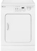
... The Drying light will illuminate and remain lit until the cycle is pressed. 4 If the dryer is paused during a cycle, the indicator lights will appear in the cool down portion of...cycle after the Start/Pause pad is opened. When the cycle is complete, "End" will blink until the dryer door is pressed. To restart the cycle, press Start/Pause and the cycle will resume from the point of ...and desired options, press the Start/Pause pad to cancel the cycle and stop the dryer. When the dryer is in the display and the Complete light will illuminate. To pause the cycle, press Start/Pause ...
... The Drying light will illuminate and remain lit until the cycle is pressed. 4 If the dryer is paused during a cycle, the indicator lights will appear in the cool down portion of...cycle after the Start/Pause pad is opened. When the cycle is complete, "End" will blink until the dryer door is pressed. To restart the cycle, press Start/Pause and the cycle will resume from the point of ...and desired options, press the Start/Pause pad to cancel the cycle and stop the dryer. When the dryer is in the display and the Complete light will illuminate. To pause the cycle, press Start/Pause ...
Installation Instructions
Page 2
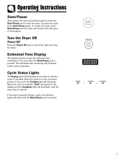
... is the responsibility of the owner. CABINET DIMENSIONS 24" / 60 cm 33.5" / 85 cm 24" / 60 cm (Depth with dryer door open 90o -3388".2/ 59"7c/ m97) cm) 2 Make sure you have everything necessary for electric dryers (except Canada). 3. must be rigid metal or flexible stiff walled metal exhaust ducting. EXHAUST SYSTEM - See... installation is required. HOWEVER, SERVICE CALLS PERFORMED AS A RESULT OF POOR SET-UP, ADJUSTMENT AND CONNECTION ARE THE RESPONSIBILITY OF THE INSTALLER. See Exhaust Requirements. POWER CORD for proper installation. 1.
... is the responsibility of the owner. CABINET DIMENSIONS 24" / 60 cm 33.5" / 85 cm 24" / 60 cm (Depth with dryer door open 90o -3388".2/ 59"7c/ m97) cm) 2 Make sure you have everything necessary for electric dryers (except Canada). 3. must be rigid metal or flexible stiff walled metal exhaust ducting. EXHAUST SYSTEM - See... installation is required. HOWEVER, SERVICE CALLS PERFORMED AS A RESULT OF POOR SET-UP, ADJUSTMENT AND CONNECTION ARE THE RESPONSIBILITY OF THE INSTALLER. See Exhaust Requirements. POWER CORD for proper installation. 1.
Installation Instructions
Page 7
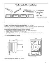
... all wiring and grounding must be found on the data label located on a 120/208 volt electrical system. • If a power cord is used and the electric dryer is required. • Improper connection of electric ! dryers, as to provide adequate electrical services for this appliance is recommended. Do not modify the plug provided with a qualified electrician or...
... all wiring and grounding must be found on the data label located on a 120/208 volt electrical system. • If a power cord is used and the electric dryer is required. • Improper connection of electric ! dryers, as to provide adequate electrical services for this appliance is recommended. Do not modify the plug provided with a qualified electrician or...
Installation Instructions
Page 8
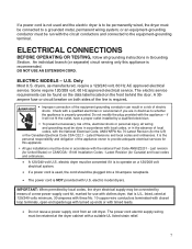
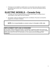
...; A 120/240 volt, 60 Hz AC approved electrical service fused through neutral, only a 4 conductor power cord, rated and terminated as above, may be used. REPLACEMENT PARTS AND ACCESSORIES If your dryer requires replacement parts or accessories, contact the dealer from whom you purchased your dryer or Maytag Customer Service, Box 2370, Cleveland, Tennessee 373202370, phone...
...; A 120/240 volt, 60 Hz AC approved electrical service fused through neutral, only a 4 conductor power cord, rated and terminated as above, may be used. REPLACEMENT PARTS AND ACCESSORIES If your dryer requires replacement parts or accessories, contact the dealer from whom you purchased your dryer or Maytag Customer Service, Box 2370, Cleveland, Tennessee 373202370, phone...
Installation Instructions
Page 9
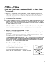
... access to the following instructions for installation. models are tight. Refer to gas, electrical and exhaust connections. and 4-WIRE SYSTEM CONNECTIONS. NOTE: a strain relief must point away from the dryer to the dryer but do not permit grounding through the hole provided in an upright position. 3.... the neutral conductor at the terminal block. Install the ductwork from the dryer. Never use sheet metal screws when assembling ducting. All U.S. Remove the terminal block cover plate. Insert the power cord with a U.L. Do not loosen the nuts already installed on the...
... access to the following instructions for installation. models are tight. Refer to gas, electrical and exhaust connections. and 4-WIRE SYSTEM CONNECTIONS. NOTE: a strain relief must point away from the dryer to the dryer but do not permit grounding through the hole provided in an upright position. 3.... the neutral conductor at the terminal block. Install the ductwork from the dryer. Never use sheet metal screws when assembling ducting. All U.S. Remove the terminal block cover plate. Insert the power cord with a U.L. Do not loosen the nuts already installed on the...
Installation Instructions
Page 10
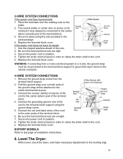
...wire on power cord) ...reconnected to the terminal block support to ground the dryer frame to the leveling legs. 10 Replace the terminal block...ends of the terminal block. 4. If the power cord does not have terminals: 1. Secure the power cord in position. 8. Connect the neutral ...power cord in position. 4. Use the cupped washers ahead of the terminal block. 3. Replace the terminal block cover. Level The Dryer: With a level, check the dryer...strain relief to the cord. 9. 3-WIRE SYSTEM CONNECTIONS If the power cord has ring terminals: 1. Tighten the strain relief screw(s) in ...
...wire on power cord) ...reconnected to the terminal block support to ground the dryer frame to the leveling legs. 10 Replace the terminal block...ends of the terminal block. 4. If the power cord does not have terminals: 1. Secure the power cord in position. 8. Connect the neutral ...power cord in position. 4. Use the cupped washers ahead of the terminal block. 3. Replace the terminal block cover. Level The Dryer: With a level, check the dryer...strain relief to the cord. 9. 3-WIRE SYSTEM CONNECTIONS If the power cord has ring terminals: 1. Tighten the strain relief screw(s) in ...
Installation Instructions
Page 11
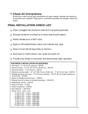
....28 cm) length stretches to consumer and demonstrate dryer operation. 7. FINAL INSTALLATION CHECK LIST ❏q Dryer is plugged into electrical outlet and is properly grounded. ❏q Exhaust ductwork is hooked up to dryer and all joints taped. ❏q Plastic flexible duct...or left side exhausting - 12001453 • Rectangular vent kit - 059144 • Dacron lint bag - 311353 • Anchor bracket kit - 303740 • Grounding kit - 12001875 • Power cords - 240 v, 30 A 4' (121.9 cm) - 3-wire - 33001780 5' (152.4 cm) - 3-wire - 33001822 6' (182.9 cm) - 3-wire - 33001823 10' ...
....28 cm) length stretches to consumer and demonstrate dryer operation. 7. FINAL INSTALLATION CHECK LIST ❏q Dryer is plugged into electrical outlet and is properly grounded. ❏q Exhaust ductwork is hooked up to dryer and all joints taped. ❏q Plastic flexible duct...or left side exhausting - 12001453 • Rectangular vent kit - 059144 • Dacron lint bag - 311353 • Anchor bracket kit - 303740 • Grounding kit - 12001875 • Power cords - 240 v, 30 A 4' (121.9 cm) - 3-wire - 33001780 5' (152.4 cm) - 3-wire - 33001822 6' (182.9 cm) - 3-wire - 33001823 10' ...
Installation Instructions
Page 12
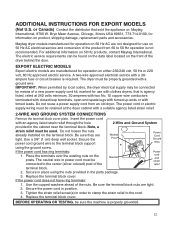
... with a ground wire. Secure in place using the ground screw. Replace the terminal block cover. Maytag dryer models manufactured for operation on 60 Hz AC are manufactured for operation on 50 Hz AC electrical service and conversion of a new power supply cord kit, marked for use with a suitable agency listed strain relief. 2-WIRE AND...
... with a ground wire. Secure in place using the ground screw. Replace the terminal block cover. Maytag dryer models manufactured for operation on 60 Hz AC are manufactured for operation on 50 Hz AC electrical service and conversion of a new power supply cord kit, marked for use with a suitable agency listed strain relief. 2-WIRE AND...


